EP0551232B1 - Vorrichtung zum Greifen und Umsetzen von Pflanzenballen - Google Patents
Vorrichtung zum Greifen und Umsetzen von Pflanzenballen Download PDFInfo
- Publication number
- EP0551232B1 EP0551232B1 EP93400026A EP93400026A EP0551232B1 EP 0551232 B1 EP0551232 B1 EP 0551232B1 EP 93400026 A EP93400026 A EP 93400026A EP 93400026 A EP93400026 A EP 93400026A EP 0551232 B1 EP0551232 B1 EP 0551232B1
- Authority
- EP
- European Patent Office
- Prior art keywords
- blades
- bar
- conveyor
- move
- support
- Prior art date
- Legal status (The legal status is an assumption and is not a legal conclusion. Google has not performed a legal analysis and makes no representation as to the accuracy of the status listed.)
- Expired - Lifetime
Links
- 239000002689 soil Substances 0.000 title claims description 9
- 230000000694 effects Effects 0.000 claims description 8
- 230000005484 gravity Effects 0.000 claims description 3
- 230000004913 activation Effects 0.000 claims 1
- 210000004027 cell Anatomy 0.000 description 47
- 125000006850 spacer group Chemical group 0.000 description 8
- 238000000926 separation method Methods 0.000 description 3
- 238000002054 transplantation Methods 0.000 description 3
- 238000005452 bending Methods 0.000 description 1
- 239000000969 carrier Substances 0.000 description 1
- 230000006378 damage Effects 0.000 description 1
- 230000005489 elastic deformation Effects 0.000 description 1
- 238000000605 extraction Methods 0.000 description 1
- 230000035784 germination Effects 0.000 description 1
- 210000004349 growth plate Anatomy 0.000 description 1
- 238000005192 partition Methods 0.000 description 1
- 230000000149 penetrating effect Effects 0.000 description 1
- 238000004382 potting Methods 0.000 description 1
- 238000009331 sowing Methods 0.000 description 1
Images

Classifications
-
- A—HUMAN NECESSITIES
- A01—AGRICULTURE; FORESTRY; ANIMAL HUSBANDRY; HUNTING; TRAPPING; FISHING
- A01G—HORTICULTURE; CULTIVATION OF VEGETABLES, FLOWERS, RICE, FRUIT, VINES, HOPS OR SEAWEED; FORESTRY; WATERING
- A01G9/00—Cultivation in receptacles, forcing-frames or greenhouses; Edging for beds, lawn or the like
- A01G9/08—Devices for filling-up flower-pots or pots for seedlings; Devices for setting plants or seeds in pots
- A01G9/086—Devices for repotting
-
- A—HUMAN NECESSITIES
- A01—AGRICULTURE; FORESTRY; ANIMAL HUSBANDRY; HUNTING; TRAPPING; FISHING
- A01C—PLANTING; SOWING; FERTILISING
- A01C11/00—Transplanting machines
- A01C11/02—Transplanting machines for seedlings
- A01C11/025—Transplanting machines using seedling trays; Devices for removing the seedlings from the trays
Definitions
- the present invention relates to a device for gripping and transferring plants in clods, in particular for transplanting and transplanting plants into mini-clods.
- a device of this type comprising, for gripping a plant rooted in a clod contained in a cell, for example a plate with alveoli, a gripper-shaped gripping element comprising two elastic gripping blades mounted in cantilever on a support so as to be at a distance and facing each other, and means for animating said blades of a reciprocating movement between a high position and a low position and of a reciprocating movement in the direction of approximation and spacing of the free ends of the blades.
- the elastic blades can be rigidly fixed to a frame so as to be urged elastically in the direction of the separation of the free ends of the two blades from one another.
- This mount is movable vertically relative to a support, under the action of a jack mounted on the latter, said support also carrying guide means which cooperate with the blades, when the latter are lowered to the low position, to bring their free ends closer to each other by elastic deformation of the blades.
- This known device although very effective, still remains perfectible, in particular for gripping clods in flat-bottomed cells and for gripping mini-clods.
- the movement of the free ends of the blades is linked to the movement of the blades down, these two movements controlled by the same cylinder overlap, that is to say that the movement of blade reconciliation begins before the blade lowering movement is completed. Consequently, the free ends of the blades describe in the cell, towards the end of the descent movement, a trajectory in an arc of a circle, while for a good grip of the root ball, with the minimum of disturbance or destruction of the roots of the plant, it would be desirable that the free ends of the blades follow as well as possible the rectilinear walls and the flat bottom of the cell.
- this known gripping device because of its structure, cannot be miniaturized so that, while being simple in structure, it can also be used for transplanting plants into mini-clods at a high rate. mini-cell plates, for example with cells having a side or diameter of less than 10 mm, the use of which is essential for reasons of profitability.
- the present invention relates to a device for gripping and transferring plants into clods which is better suited than known devices for gripping clods in flat-bottomed cells.
- the invention also relates to a device for gripping and transferring plants into clods which can be miniatured so as to also be suitable for gripping mini-clods in cells of small sizes and very close together.
- the invention relates to a device for gripping and transferring plants in clods allowing, while being simple in structure, transplantation at a high rate.
- the device according to the invention for gripping and transferring plants in clods, in particular for transplanting and transplanting plants into mini-clods comprises, for gripping a clod plant in a cell, a gripping element comprising two blades of elastic gripping mounted cantilevered on a support so as to be at a distance and facing one another, and means for moving said blades back and forth between a position high and a low position, and a back-and-forth movement in the direction of approximation and spacing of the free ends of the blades.
- the two blades of the gripping element are shaped and rigidly fixed to the support so as to approach each other in the direction of their free ends.
- the support is animated by first means for maneuvering a vertical movement back and forth between a high position and a low position.
- a spacer element is mounted on said support in a movable manner, under the action of second operating means, between a first position in which it does not act on said blades, and therefore leaves their free ends approaching one of the other under the effect of the elasticity of the blades, and a second position in which it acts on said blades so as to separate from one another the free ends of the blades against the elasticity of these last.
- the blades can be shaped so that under the effect of their elasticity, their reciprocal distance increases from their free ends towards their location of attachment to the support.
- the spacer element can, in this case, be movable perpendicular to the blades, in the manner of a wedge, or be preferably movable in longitudinal translation between the blades.
- the first of the two positions of the spacer element is preferably at a distance from the location for fixing the blades on the support. This consequently increases the bending length of the blades when the latter are separated by the spacer element.
- the two blades can advantageously have an inflection at the location of said first position, so that the two blades can be very close to each other at their location for attachment to the support and then move apart until this inflection to then approach again up to their free ends.
- the retaining element can act by gravity on the root ball and not be driven upwards by the spacer element until the end of the movement of the latter towards said first position.
- the supports of all the gripping elements are mounted on a common support element movable vertically back and forth under the action of a means of common operation and the spacer elements of all the gripping elements are controlled by a common operation means.
- such a transplant device with multiple gripping elements comprises a first horizontal step-by-step conveyor for first cell plates containing plug plants to be transplanted.
- This device further comprises a second horizontal conveyor step by step parallel to the first conveyor, for second cell plates in which the clod plants are to be transplanted.
- a horizontal bar extends perpendicular to the carriers above the latter, said bar being vertically movable back and forth.
- a rule extends parallel to said bar above the conveyors, said rule being movable vertically back and forth relative to the bar.
- the supports of the blades of the gripping elements are mounted movable in translation and immobilized in rotation on said bar and the spacer elements of the gripping elements cooperate, with a view to their control, with said rule.
- Maneuvering means are provided for moving the bar vertically back and forth, for moving the rule vertically back and forth relative to the bar and for moving the supports of the gripping elements in translation on the bar between a first position located above the first conveyor and a second position located above the second conveyor.
- this device further comprises a comb installed in a fixed position above the first conveyor, below the gripping elements, comb whose teeth have a pitch equal to the transverse pitch of the cells of the plates of this conveyor.
- the device comprises a retractable lower stop for said bar and operating means for retracting this stop so as to define for the bar a first and a second position. lower corresponding one to the actuation and the other to the retraction of said stop.
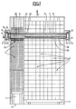
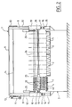
- the device as illustrated in FIGS. 1 and 2 is a transplanting machine used to remove seedlings in clumps from honeycomb plates 1 for transplanting these plants into clumps contained in the larger alveoli of honeycomb plates 2.
- the plates 1 are rectangular plates comprising for example 160 square cells distributed in sixteen transverse rows of ten cells each, while the plates 2 are rectangular plates having for example 50 cells distributed in ten transverse rows of five cells each .
- the plates 1 are sowing and germination plates having a high density of small cells, for example cells of less than 10 mm in side, while the plates 2 can, for example, be growth plates having cells of for example 40 mm or more sideways in which the plants from the plates 1 can be raised until they are transplanted, for example in pots, or until they are sold.
- the machine according to Figures 1 and 2 comprises a frame 3 on which are provided a horizontal conveyor 4 for a row of plates 1, and a horizontal conveyor 5 for two rows of plates 2.
- the two conveyors 4 and 5 advance the plates 1 and 2 in the direction of arrow 6 in FIG. 1, at the same rate, but with steps corresponding to the step of the cells of the respective plates 1, 2.
- the two conveyors 4 and 5 which receive the plates 1 and 2 are at different heights such that the upper edges of the plates 1 and 2 of different thicknesses are located substantially in the same horizontal plane.
- a gantry 7 essentially comprising two uprights 8 and an upper cross member 9.
- Two carriages 10 are mounted to slide and are guided vertically on the uprights 8, their vertical movement being controlled by an assembly comprising a pneumatic cylinder 11, two chains 12 having one of their ends fixed to the two carriages 10 and their other ends fixed to chain wheels 13 connected together by a transverse shaft 14, the jack 11 being articulated on one of the uprights 8 and on the 'one of the wheels 13 or a crank integral with this wheel so that when actuated in one direction or the other, it rotates in one direction or the other the wheel 13 in question to thereby raise and lower in synchronism the two carriages 10.
- Two pneumatic cylinders 15 are also installed on the frame 3, below the carriages 10, so that their piston rods 16 can cooperate, in the extended position of the jacks, with adjustable stops 17 provided on the carriages 10.
- the two carriages 10 are interconnected by a grooved crossbar 18 carrying a set 19 of gripping elements 20 which are movable in translation but immobilized angularly on the bar 18.
- an operating element 21 which may for example be a rodless pneumatic cylinder, of the slit or magnetic drive type, is also installed transversely. between the two carriages 10, its outlet member 22 movable over the entire length of the element 21 being coupled to a grooved sleeve 23 mounted on the grooved bar 18, on one side of the assembly 19 of the gripping elements 20. On the opposite side of the assembly 19, a stop sleeve 24 is fixed to the bar 18.
- each of the two carriages 10 is further mounted a vertical cylinder 25, the rods of the pistons of the two cylinders 25 carrying a transverse rule 26 which cooperates with the gripping elements 20 in a manner which will be described in more detail below.
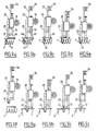
- the gripping elements 20 are shown in the position they occupy above the cell plates 1, for the removal of a row of clods in the one of said plates.
- the gripping elements 20 are brought, by sliding on the grooved bar 18 under the action of the operating element 21, above the cell plates 2 in the positions indicated in phantom in Figure 2.
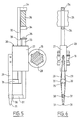
- Each gripping element 20 comprises a rectangular plate 27 carrying on one of its large edges a grooved ring 28 internally slidably mounted on the grooved bar 18.
- the plate 27 On its opposite large edge, the plate 27 carries two elastic blades 29 fixed in carrier overhang downwards to the plate 27.
- each blade 29 has an inflection 30 substantially at mid-length and the two blades 29 are arranged symmetrically with respect to each other so that under the effect of their elasticity, the two blades 29 fixed close to one another to the plate 27 are spaced from one another at the place of their inflections 30 and are on the other hand in contact with the one with the other at the location of their free ends 31 which, as shown in FIGS. 3 and 5, are tapered.
- the rod 32 carries at its upper end two horizontal fingers 34 spaced vertically a distance slightly greater than the height of the rule 26, which is engaged between the two fingers 34 At its lower end projecting downwards from the plate 27, the rod 32 carries a horizontal finger 35 which is engaged between the two blades 29 and has a diameter substantially equal to the distance separating the two blades 29 from one another. at the place of their inflections 30.
- the other rod 33 carries at its upper end projecting from the plate 27 upwards a washer 36 fixed for example by means of a screw and projecting over the rod 33. At its lower end, the rod 33 carries a horizontal finger 37 whose free end 38 engaged between the two blades 29 below the finger 35 of the rod 32 is tapered.
- the clamp formed by the two blades 29 is opened by the fact that the rod 32 is lowered by the rule 26, so that the finger 35 is in a vertical position intermediate between the inflections 30 of the blades 29 and the free ends 31 of these blades and thus separates the free ends 31 of the blades 29 from one another against the elasticity of the blades.
- the rod 33 occupies by gravity a low position defined by the washer 35 abutting against the upper edge of the plate 27, position in which the finger 37 is located practically at the free ends 31 of blades 29.
- the rod 33 is raised relative to the plate 27 by the rod 32 which has a shoulder 39 cooperating with washer 35 towards the end of its movement mounted, so that the finger 37 is at a distance above the free ends 31 of the blades 29.
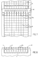
- the comb 40 is installed transversely above the conveyor 4 for the cell plates 1, so that the teeth 40a of the comb whose pitch is equal to the transverse pitch of the cells 41 of the plates 1 located at a distance above the upper edge of the plates 1.
- the teeth 40a of the comb 40 are long enough to be able to receive between them the fingers 37 of the rods 33 of the gripping elements 20.
- the teeth 40a of the comb 40 being vertically above the partitions between the cells 41 of the same row, these teeth provide centering, relative to the cells 41, of the blades 29 of the various gripping elements 20 when, as described in more detail below, the gripping elements 20 are lowered, the blades 29 of each element 20 being brought towards one another in the position according to FIG. 6, until the points 31 of the blades 29 are located below the teeth 40a, but above the upper face of the cell plate 1, and are then moved to the position according to FIG. 4. Consequently, after such prior centering of the gripping elements 20 by the teeth 40a of the comb 40, the blades 29 can be inserted into the cells 41 without risk of catching on the walls of the cells.
- the plate 1 At the start of the transplant cycle, the plate 1 is in the position it occupies at the end of the previous cycle, that is to say that the row of cells 41 whose clods were transplanted during the cycle above is located below the blades 29 of the gripping elements 20, the latter being brought close to each other above the plate 1, as shown in solid lines in FIG. 2.
- the two blades 29 forming pliers of each element of gripping 20 are therefore located above a cell 41 of this row of cells, the two blades 29 of each clamp being separated, by the fact that the rule 26 is lowered relative to the grooved bar 18, by the jacks 25.
- the actuators 25 are first actuated to lift the rule 26, so as to bring the blades 29, that is to say close the clamps, and the actuators 15 are actuated to lift their piston rods 16. Then, in a second step, the actuator 11 is actuated so as to lower the two carriages 10 as far as the stop on the piston rods 16 of the cylinders 15, which according to FIG. 9a causes the set of gripping elements 20 until the free ends 31 of their blades 29 are slightly below the teeth 40a of the comb 40, without however penetrating into the cells 41 of the plate 1.
- the chains 12, by their flexibility compensate for the reduction in travel due to the stop of the carriages 10 on the piston rods 16 of the jacks.
- the blades 29 are then moved aside from the gripping elements 20, by actuating the jacks 25 which thus lower the rule 26 relative to the grooved bar 18. Due to this movement of separation of the blades 29, the latter are centered on the cells 41 of the plate 1 by the teeth 40a of the comb 40.
- the cell plate 1 is then advanced by one step so that the cells of the next row, each containing a plug plant 42, are located below the blades 29 of the gripping elements 20.
- the next phase of the cycle consists in driving the blades 29 of the gripping elements 20 into the cells of said row, by actuating the jacks 15 in the direction of retraction of their piston rods 16, which allows the carriage 10, under the effect of the weight of the mobile assembly to descend to a position defined by the re-tensioning of the chains 12.
- the pliers are then closed, that is to say the blades 29 of each gripping element 20 are brought closer to one another by actuating the jacks 25 in the direction of lifting the rule 26, so that the clods 42 contained in the cells in which the blades 29 have entered before being close together are gripped by said blades.
- the blades 29 are then lifted close together by actuating the jack 11 which, by the chains 12, lifts the two carriages 10 and all the elements mounted on these carriages (grooved bar 18, gripping elements 20, rule 26) so that the clods 42 gripped by the blades 29 are lifted out of the cells of the plate 1.
- the translation jack 21 is actuated so that the outlet member 22 of the latter moves to the right in FIG. 1 and drives the gripping elements 20, by spreading them apart others, at the positions indicated in phantom in Figure 2, so that each gripping element 20 carrying a clod 42 is placed above a cell of the two plates 2 juxtaposed.
- the cells of the plates 2 were previously filled with an appropriate culture support, for example potting soil.
- the gripping elements 20 are then lowered, by actuating the jack 11 which lowers the mobile assembly, in order to push the clods 42 into the culture support contained in the cells of the plates 2.
- the pliers are then opened, that is to say the blades 29 are separated from the gripping elements 20 by controlling the jacks 25 so that they raise the rule 26, so that the blades 29 release clod 42.
- the gripping elements 20 are lifted in order to remove their separated blades 29 from the plates 2, by actuating the jack 11 so that it lifts the carriages 10 and all of the elements mounted on these carriages.
Landscapes
- Life Sciences & Earth Sciences (AREA)
- Environmental Sciences (AREA)
- Soil Sciences (AREA)
- Hydroponics (AREA)
- Cultivation Of Plants (AREA)
- Pretreatment Of Seeds And Plants (AREA)
- Specific Conveyance Elements (AREA)
Claims (9)
- Greif- und Umsetzvorrichtung für Pflanzen mit Ballen, insbesondere zum Pikieren und zum Umsetzen von Pflanzen mit kleinem Ballen, mit einem Greifelement, das zwei Greifklingen (29) aufweist, die an einem Halter (27) vorragend und einander gegenüberstehend starr befestigt sind, und mit Mitteln, die die genannten Klingen veranlassen, eine Pflanze mit Ballen in einem Topf durch eine Absenkbewegung zwischen einer oberen Stellung und einer unteren Stellung und durch eine Annäherungsbewegung der freien Enden der Klingen zu ergreifen und eine Pflanze mit Ballen durch eine Spreizbewegung der freien Enden der Klingen und durch eine Hubbewegung der Klingen zwischen einer unteren Stellung und einer oberen Stellung loszulassen, dadurch gekennzeichnet, daß die beiden Klingen (29) des Greifelementes (20) an dem Halter (27) befestigt und derart ausgebildet sind, daß sie sich unter der alleinigen Wirkung ihrer Elastizität in Richtung auf ihre freien Enden (31) zu einander annähern, daß dem Halter (27) von ersten Betätigungsmitteln (11, 18) eine vertikale Hin- und Herbewegung zwischen der oberen Stellung und der unteren Stellung erteilt wird, und daß ein Spreizmittel (35) auf dem Halter (27) derart gelagert ist, daß es unter der Einwirkung von zweiten Betätigungsmitteln (25, 26) zwischen einer ersten Stellung, in der es nicht auf die Klingen (29) einwirkt und deren freie Enden (31) sich unter der Wirkung der Elastizität der Klingen einander annähern läßt, und einer zweiten Stellung beweglich ist, in der es auf die Klingen derart einwirkt, daß sich die freien Enden (31) der Klingen entgegen der Wirkung der Elastizität dieser letzteren voneinander abspreizen.
- Vorrichtung nach Anspruch 1, dadurch gekennzeichnet, daß das Spreizmittel (35) zwischen den Klingen (29) längsverstellbar ist.
- Vorrichtung nach Anspruch 2, dadurch gekennzeichnet, daß sich die erste der beiden Stellungen des Spreizmittels (35) in einem Abstand von der Befestigungsstelle der Klingen (29) auf dem Halter (27) befindet.
- Vorrichtung nach Anspruch 3, dadurch gekennzeichnet, daß die beiden Klingen (29) an ihrer Befestigungsstelle sehr nahe beieinander stehen und an dem Ort der genannten ersten Stellung eine Einbiegung (30) aufweisen.
- Vorrichtung nach einem der vorstehenden Ansprüche, dadurch gekennzeichnet, daß ein auf dem Halter (27) parallel zu den Klingen (29) beweglich angebrachtes Abhaltemittel (37) den Klingen (29) des Greifelementes (20) zugeordnet ist, um den Ballen von den gespreizten Klingen abzustossen.
- Vorrichtung nach Anspruch 5, dadurch gekennzeichnet, daß das Anhaltemittel (37) von dem Spreizmittel (35) so gesteuert ist, daß das Abhaltemittel mittels Schwerkraft auf den Ballen einwirkt und von dem Spreizmittel erst gegen Ende dessen Bewegung auf die genannte erste Stellung zu nach oben mitgenommen wird.
- Vorrichtung nach einem der vorstehenden Ansprüche mit mehreren Greifelementen, dadurch gekennzeichnet, daß die Halter (27) aller Greifelemente (20) auf einem gemeinsamen, unter der Einwirkung eines gemeinsamen Betätigungsmittels (11) in vertikaler Richtung hin- und herbeweglichen Haltemittel (18) gelagert sind und daß die Spreizmittel (35) aller Greifelemente (20) durch ein gemeinsames Betätigungsmittel (26, 25) gesteuert sind.
- Vorrichtung nach Anspruch 7, dadurch gekennzeichnet, daß sie aufweist: einen horizontalen schrittweise arbeitenden ersten Förderer (4) für erste Topfplatten (1), welche umzusetzende Pflanzen mit Ballen (42) enthalten, einen horizontalen, zu dem ersten Förderer parallelen, schrittweise arbeitenden zweiten Förderer (5) für zweite Topfplatten (2), in welche die Pflanzen mit Ballen umgesetzt werden sollen, eine horizontale Stange (18), die sich rechtwinklig zu den Förderern (4, 5) oberhalb derselben erstreckt, wobei die Stange in vertikaler Richtung hin- und herbeweglich ist, eine Schiene (26), die sich parallel zu der Stange (18) oberhalb der Förderer (4, 5) erstreckt, wobei die Schiene gegenüber der Stange in vertikaler Richtung hin- und herbeweglich ist, wobei die Träger (27) der Klingen (29) der Greifelemente (20) längsverschieblich und drehfest auf der Stange (18) gelagert sind, die Spreizmittel (35) der Greifmittel (20) zu ihrer Steuerung mit der Schiene (26) zusammenwirken und Betätigungsmittel (11, 25, 21) vorgesehen sind, um die Stange (18) in vertikaler Richtung hin- und herzubewegen, um die Schiene (26) in vertikaler Richtung bezüglich der Stange (18) hin- und herzubewegen und um die Halter (27) der Greifelemente (20) auf der Stange (18) in Längsrichtung jeweils zwischen einer ersten oberhalb des ersten Förderers (4) befindlichen Stellung und einer zweiten oberhalb des zweiten Förderers (5) befindlichen Stellung zu verschieben.
- Vorrichtung nach Anspruch 8, dadurch gekennzeichnet, daß sie darüber hinaus aufweist: einen ortsfest oberhalb des ersten Förderers (4) und unterhalb der Greifelemente (20) angeordneten Kamm (40), wobei die Zähne (40a) des Kamms eine Schrittweite aufweisen, die gleich der transversalen Schrittweite der Töpfe (41) der Platten (1) dieses Förderers ist, ein unwirksam machbares unteres Anschlagmittel (16, 17), um die Ansenkbewegung der Stange (18) zu begrenzen, und Betätigungsmittel (15), um dieses Anschlagmittel derart unwirksam zu machen, daß für die Stange eine erste und eine zweite untere Stellung festgelegt ist, wobei die eine dem Wirksamsein und die andere dem Unwirksamsein des Anschlagmittels entspricht.
Applications Claiming Priority (2)
| Application Number | Priority Date | Filing Date | Title |
|---|---|---|---|
| FR9200086 | 1992-01-07 | ||
| FR9200086A FR2685852B1 (fr) | 1992-01-07 | 1992-01-07 | Dispositif de prehension et de transfert de plants en mottes. |
Publications (2)
| Publication Number | Publication Date |
|---|---|
| EP0551232A1 EP0551232A1 (de) | 1993-07-14 |
| EP0551232B1 true EP0551232B1 (de) | 1995-09-13 |
Family
ID=9425440
Family Applications (1)
| Application Number | Title | Priority Date | Filing Date |
|---|---|---|---|
| EP93400026A Expired - Lifetime EP0551232B1 (de) | 1992-01-07 | 1993-01-07 | Vorrichtung zum Greifen und Umsetzen von Pflanzenballen |
Country Status (4)
| Country | Link |
|---|---|
| EP (1) | EP0551232B1 (de) |
| DE (1) | DE69300457T2 (de) |
| ES (1) | ES2079945T3 (de) |
| FR (1) | FR2685852B1 (de) |
Families Citing this family (12)
| Publication number | Priority date | Publication date | Assignee | Title |
|---|---|---|---|---|
| NL9302172A (nl) * | 1993-12-13 | 1995-07-03 | Flier Bv Geb | Werkwijze en inrichting voor het manipuleren van substraat met daarin opgenomen gewas. |
| FR2715531B1 (fr) * | 1994-02-02 | 1996-04-19 | Claude Ferrand | Dispositif de repiquage rapide de végétaux. |
| EP0712569B1 (de) * | 1994-11-17 | 2000-01-05 | YANMAR AGRICULTURAL EQUIPMENT Co., Ltd. | Pflanzmaschine |
| FR2737642B1 (fr) * | 1995-08-11 | 1997-10-31 | Gaudillat Christian | Machine a repiquer, dans des godets ou des pots, des plants sur mini-mottes contenues dans des alveoles |
| EP0948886A1 (de) | 1998-04-09 | 1999-10-13 | Gerplant Automation | Verfahren um Pflanzen in Erdballen zu transferieren und Greiferkopf um dieses Verfahren auszuführen |
| NL1011638C2 (nl) * | 1999-03-22 | 2000-09-27 | W J Heemskerk & Zn | Inrichting en werkwijze voor het splitsen van vaste planten. |
| FR2802386B1 (fr) | 1999-12-16 | 2002-03-22 | Claude Ferrand | Robot de repiquage de vegetaux |
| WO2002052922A1 (fr) | 2000-12-29 | 2002-07-11 | Claude Ferrand | Robot de repiquage de vegetaux |
| FR2820608B1 (fr) * | 2001-02-09 | 2003-09-05 | Gerplant Automation | Procede et dispositif de prehension de mottes dans des plaques alveolees, notamment pour la transplantation de plants en mottes en culture horticole ou maraichere |
| FR2828061B1 (fr) | 2001-08-06 | 2003-11-14 | Robin Pepinieres | Dispositif pour le repiquage de plants |
| CN103098597B (zh) * | 2012-12-08 | 2015-01-07 | 宁波市鄞州云帆工程咨询有限公司 | 伸缩式秧苗移植器 |
| NL2014155B3 (en) * | 2015-01-19 | 2024-04-11 | Ig Specials B V | Apparatus and method for planting plant cuttings. |
Citations (1)
| Publication number | Priority date | Publication date | Assignee | Title |
|---|---|---|---|---|
| FR2614499A1 (fr) * | 1987-04-28 | 1988-11-04 | Gerplant Automation | Dispositif de prehension et de transfert de plants en mottes |
Family Cites Families (3)
| Publication number | Priority date | Publication date | Assignee | Title |
|---|---|---|---|---|
| NL7900943A (nl) * | 1979-02-06 | 1980-08-08 | Stichting Inst Mech | Plantenstekoverzetinrichting. |
| NL8800040A (nl) * | 1988-01-08 | 1989-08-01 | Visser S Gravendeel Holding | Inrichting voor het aangrijpen van van een plant voorziene kluiten. |
| NL190977C (nl) * | 1988-08-31 | 1994-12-01 | Visser S Gravendeel Holding | Inrichting voor het aangrijpen en loslaten van kluiten met planten. |
-
1992
- 1992-01-07 FR FR9200086A patent/FR2685852B1/fr not_active Expired - Fee Related
-
1993
- 1993-01-07 DE DE1993600457 patent/DE69300457T2/de not_active Expired - Fee Related
- 1993-01-07 EP EP93400026A patent/EP0551232B1/de not_active Expired - Lifetime
- 1993-01-07 ES ES93400026T patent/ES2079945T3/es not_active Expired - Lifetime
Patent Citations (1)
| Publication number | Priority date | Publication date | Assignee | Title |
|---|---|---|---|---|
| FR2614499A1 (fr) * | 1987-04-28 | 1988-11-04 | Gerplant Automation | Dispositif de prehension et de transfert de plants en mottes |
Also Published As
| Publication number | Publication date |
|---|---|
| FR2685852B1 (fr) | 1999-02-19 |
| ES2079945T3 (es) | 1996-01-16 |
| FR2685852A1 (fr) | 1993-07-09 |
| EP0551232A1 (de) | 1993-07-14 |
| DE69300457D1 (de) | 1995-10-19 |
| DE69300457T2 (de) | 1996-05-09 |
Similar Documents
| Publication | Publication Date | Title |
|---|---|---|
| EP0197976B1 (de) | Verfahren um setzlinge in erdballen zu behandeln | |
| EP0551232A1 (de) | Vorrichtung zum Greifen und Umsetzen von Pflanzenballen | |
| EP0243264A1 (de) | Pflanzmaschine und Verfahren zum pflanzen für Setzlinge in Topfballen | |
| EP1377155B1 (de) | Umpflanzungsmaschine | |
| EP0033670B1 (de) | Verfahren und Vorrichtung zum Ausformen von Weichkäse | |
| FR2802386A1 (fr) | Robot de repiquage de vegetaux | |
| FR2693344A1 (fr) | Machine de repiquage automatique de mini-mottes. | |
| CN112930772A (zh) | 一种果树苗种植挖坑同步式机械化装置 | |
| FR2635637A1 (fr) | Appareil prehenseur a detachement automatique pour transferer des plantes | |
| FR2574252A1 (fr) | Installation pour la fabrication automatisee de brochettes | |
| US4646598A (en) | Brick cutting and handling apparatus having movable wire bank cutter assembly | |
| FR2618043A1 (fr) | Procede de separation automatique des endives de leurs racines, et machine pour la mise en oeuvre de ce procede | |
| EP0083591B1 (de) | Elektrolysevorrichtung | |
| EP0742684B1 (de) | Schnellpflanzgerät für topfballen | |
| EP1266559B1 (de) | Vorrichtung zum automatisches Ernten von aus dem Boden auftauchenden Pflanzen | |
| EP0465327A2 (de) | Vorrichtung für die Errichtung von Kulturtunneln | |
| EP0298834A1 (de) | Vorrichtung zum schrittweisen Fördern entlang einer Förderbahn, insbesondere zum Fördern einer Reihe von Gegenständen in eine Förderrichtung | |
| EP1230838A1 (de) | Verfahren und Vorrichtung zum Greifen von Pflanzenballen von einer Kultivationspalette, insbesondere zum Umsetzen von Pflanzenballen für den Gartenbau | |
| FR2738988A1 (fr) | Machine automatique permettant de realiser le depotage et rempotage de plants et dispositif permettant la manutention desdits plants utilisables sur une telle machine | |
| FR2474271A1 (fr) | Procede et dispositif d'alimentation en plants en pots detaches d'une plaque pour machine a planter, applicables notamment a des plantations forestieres | |
| EP0611519A1 (de) | Pflanzmaschine für Erdballen-Setzlinge | |
| FR2737642A1 (fr) | Machine a repiquer, dans des godets ou des pots, des plants sur mini-mottes contenues dans des alveoles | |
| FR2464657A1 (fr) | Machine pour la preparation de legumes ombelliferes | |
| EP1285573B1 (de) | Umpflanzungsvorrichtung | |
| FR2722949A1 (fr) | Dispositif de detroquage de tuiles de collecte de naissains d'huitres et tuiles de collecte associees |
Legal Events
| Date | Code | Title | Description |
|---|---|---|---|
| PUAI | Public reference made under article 153(3) epc to a published international application that has entered the european phase |
Free format text: ORIGINAL CODE: 0009012 |
|
| AK | Designated contracting states |
Kind code of ref document: A1 Designated state(s): BE DE ES GB IT NL PT |
|
| 17P | Request for examination filed |
Effective date: 19930823 |
|
| 17Q | First examination report despatched |
Effective date: 19941123 |
|
| GRAA | (expected) grant |
Free format text: ORIGINAL CODE: 0009210 |
|
| AK | Designated contracting states |
Kind code of ref document: B1 Designated state(s): BE DE ES GB IT NL PT |
|
| REF | Corresponds to: |
Ref document number: 69300457 Country of ref document: DE Date of ref document: 19951019 |
|
| ITF | It: translation for a ep patent filed | ||
| PG25 | Lapsed in a contracting state [announced via postgrant information from national office to epo] |
Ref country code: PT Effective date: 19951213 |
|
| GBT | Gb: translation of ep patent filed (gb section 77(6)(a)/1977) |
Effective date: 19951212 |
|
| REG | Reference to a national code |
Ref country code: ES Ref legal event code: FG2A Ref document number: 2079945 Country of ref document: ES Kind code of ref document: T3 |
|
| PLBE | No opposition filed within time limit |
Free format text: ORIGINAL CODE: 0009261 |
|
| STAA | Information on the status of an ep patent application or granted ep patent |
Free format text: STATUS: NO OPPOSITION FILED WITHIN TIME LIMIT |
|
| 26N | No opposition filed | ||
| REG | Reference to a national code |
Ref country code: GB Ref legal event code: IF02 |
|
| PGFP | Annual fee paid to national office [announced via postgrant information from national office to epo] |
Ref country code: GB Payment date: 20050125 Year of fee payment: 13 |
|
| PGFP | Annual fee paid to national office [announced via postgrant information from national office to epo] |
Ref country code: ES Payment date: 20050126 Year of fee payment: 13 |
|
| PGFP | Annual fee paid to national office [announced via postgrant information from national office to epo] |
Ref country code: NL Payment date: 20050131 Year of fee payment: 13 Ref country code: DE Payment date: 20050131 Year of fee payment: 13 |
|
| PGFP | Annual fee paid to national office [announced via postgrant information from national office to epo] |
Ref country code: BE Payment date: 20050216 Year of fee payment: 13 |
|
| PG25 | Lapsed in a contracting state [announced via postgrant information from national office to epo] |
Ref country code: GB Free format text: LAPSE BECAUSE OF NON-PAYMENT OF DUE FEES Effective date: 20060107 |
|
| PG25 | Lapsed in a contracting state [announced via postgrant information from national office to epo] |
Ref country code: ES Free format text: LAPSE BECAUSE OF NON-PAYMENT OF DUE FEES Effective date: 20060109 |
|
| PG25 | Lapsed in a contracting state [announced via postgrant information from national office to epo] |
Ref country code: BE Free format text: LAPSE BECAUSE OF NON-PAYMENT OF DUE FEES Effective date: 20060131 |
|
| PGFP | Annual fee paid to national office [announced via postgrant information from national office to epo] |
Ref country code: IT Payment date: 20060131 Year of fee payment: 14 |
|
| PG25 | Lapsed in a contracting state [announced via postgrant information from national office to epo] |
Ref country code: NL Free format text: LAPSE BECAUSE OF NON-PAYMENT OF DUE FEES Effective date: 20060801 Ref country code: DE Free format text: LAPSE BECAUSE OF NON-PAYMENT OF DUE FEES Effective date: 20060801 |
|
| GBPC | Gb: european patent ceased through non-payment of renewal fee |
Effective date: 20060107 |
|
| NLV4 | Nl: lapsed or anulled due to non-payment of the annual fee |
Effective date: 20060801 |
|
| REG | Reference to a national code |
Ref country code: ES Ref legal event code: FD2A Effective date: 20060109 |
|
| BERE | Be: lapsed |
Owner name: *GERPLANT AUTOMATION Effective date: 20060131 |
|
| PG25 | Lapsed in a contracting state [announced via postgrant information from national office to epo] |
Ref country code: IT Free format text: LAPSE BECAUSE OF NON-PAYMENT OF DUE FEES Effective date: 20070107 |