EP0551265B1 - Vorrichtung für fahrzeuge - Google Patents
Vorrichtung für fahrzeuge Download PDFInfo
- Publication number
- EP0551265B1 EP0551265B1 EP91906714A EP91906714A EP0551265B1 EP 0551265 B1 EP0551265 B1 EP 0551265B1 EP 91906714 A EP91906714 A EP 91906714A EP 91906714 A EP91906714 A EP 91906714A EP 0551265 B1 EP0551265 B1 EP 0551265B1
- Authority
- EP
- European Patent Office
- Prior art keywords
- chassis
- vehicle
- load carrier
- carrier arrangement
- rear chassis
- Prior art date
- Legal status (The legal status is an assumption and is not a legal conclusion. Google has not performed a legal analysis and makes no representation as to the accuracy of the status listed.)
- Expired - Lifetime
Links
- 239000012530 fluid Substances 0.000 claims description 22
- 230000001788 irregular Effects 0.000 description 4
- 239000004575 stone Substances 0.000 description 3
- 238000004891 communication Methods 0.000 description 2
- 238000010586 diagram Methods 0.000 description 2
- 239000002023 wood Substances 0.000 description 2
- 230000002349 favourable effect Effects 0.000 description 1
- 239000010720 hydraulic oil Substances 0.000 description 1
- 238000000034 method Methods 0.000 description 1
- 238000012986 modification Methods 0.000 description 1
- 238000005096 rolling process Methods 0.000 description 1
- 238000004904 shortening Methods 0.000 description 1
- 239000000725 suspension Substances 0.000 description 1
Images




Classifications
-
- A—HUMAN NECESSITIES
- A01—AGRICULTURE; FORESTRY; ANIMAL HUSBANDRY; HUNTING; TRAPPING; FISHING
- A01G—HORTICULTURE; CULTIVATION OF VEGETABLES, FLOWERS, RICE, FRUIT, VINES, HOPS OR SEAWEED; FORESTRY; WATERING
- A01G23/00—Forestry
- A01G23/003—Collecting felled trees
- A01G23/006—Log skidders
-
- A—HUMAN NECESSITIES
- A01—AGRICULTURE; FORESTRY; ANIMAL HUSBANDRY; HUNTING; TRAPPING; FISHING
- A01G—HORTICULTURE; CULTIVATION OF VEGETABLES, FLOWERS, RICE, FRUIT, VINES, HOPS OR SEAWEED; FORESTRY; WATERING
- A01G23/00—Forestry
- A01G23/003—Collecting felled trees
-
- B—PERFORMING OPERATIONS; TRANSPORTING
- B62—LAND VEHICLES FOR TRAVELLING OTHERWISE THAN ON RAILS
- B62D—MOTOR VEHICLES; TRAILERS
- B62D53/00—Tractor-trailer combinations; Road trains
- B62D53/02—Tractor-trailer combinations; Road trains comprising a uniaxle tractor unit and a uniaxle trailer unit
-
- B—PERFORMING OPERATIONS; TRANSPORTING
- B62—LAND VEHICLES FOR TRAVELLING OTHERWISE THAN ON RAILS
- B62D—MOTOR VEHICLES; TRAILERS
- B62D61/00—Motor vehicles or trailers, characterised by the arrangement or number of wheels, not otherwise provided for, e.g. four wheels in diamond pattern
- B62D61/10—Motor vehicles or trailers, characterised by the arrangement or number of wheels, not otherwise provided for, e.g. four wheels in diamond pattern with more than four wheels
Definitions
- the vehicle is in particular a load vehicle, which is especially adapted for cross-country driving.
- the vehicle may for example be a forest vehicle for transport of wood products or for carrying tree or tree trunk processors.
- a device of this nature is disclosed in SE-B-327 631 and involves vehicle flexibility on taking curves.
- the wheel suspension is of a conventional nature and leaves much to be desired as far as driving properties are concerned.
- the object of the present invention is to start from the art referred to in the preamble of claim 1 and provide a constructional solution adapted to give the vehicle good driving properties.
- This object is in accordance with the invention obtained by providing the device with the characteristics defined in the characterising part of claim 1.
- a device thus improved obtains particularly uniform and smooth running on movement of the vehicle over an irregular ground.
- the vehicle illustrated in Fig 1-5 is intended for cross country driving and has six wheels 1-6, three of which 1, 3, 5 and 2, 4, 6, respectively, are arranged on each longitudinal side of the vehicle.
- Each wheel is individually suspended in a chassis 7 of the vehicle by means of a respective vertically pivotal pivot arm 8-13.
- each of the pivot arms is pivoted with respect to the vehicle chassis 7 about an axis 14 extending substantially horizontally and transversally with respect to the longitudinal direction of the vehicle.
- Each separate wheel (see the wheel 5 in Fig 1) is rotatably mounted in bearings on the respective pivot arm about an axle 15, which is located at a distance from the pivot axis 14 of the pivot arm and substantially parallel thereto.
- a motor for instance an hydraulic motor for driving the wheel carried by the pivot arm in question, may be arranged on each of the pivot arms 8-13.
- An hydraulic cylinder 16, 17, 18, 19, 20 and 21, respectively, is arranged between each of the pivot arms 8-13 and the vehicle chassis 7.
- Each of the hydraulic cylinders is in this example pivotally connected between the respective pivot arm and the vehicle chassis, so that on extension of an hydraulic cylinder the pivot arm associated therewith will be pivoted so that the vehicle chassis is lifted.
- the hydraulic cylinders have two hydraulic fluid rooms 28-33 and 34-39, respectively, located on opposite sides of a piston 22-27 of the respective cylinder. In a first 28-33 of these rooms there is pressurized hydraulic fluid so as to counteract such pivoting of the pivot arm in question that the wheel arranged thereon is raised with respect to the vehicle chassis.
- the pivot arms are in Fig 1 illustrated in a position, in which the pivot arms extend substantially horizontally.
- the pivot arms may from this position by means of the hydraulic cylinders be pivoted downwardly with respect to the chassis about the axis 14, so that the vehicle chassis is raised with respect to the ground.
- the pivot arms may in an analogous way be pivoted at least slightly upwardly from the position according to Fig 1, so that the vehicle chassis may be lowered with respect to the ground.
- the pivot arms 8-9 are so arranged that the wheel axle 15 as seen in the normal moving direction M of the vehicle is located in front of the pivot axis 14 of the corresponding pivot arm with respect to the chassis. However, the axles 15 are located behind the pivot axis 14 for the pivot arms 10-13.
- the hydraulic cylinders 16-21 are for cross country driving coupled or may be coupled for mutual cooperation in the closed circuit illustrated in Fig 6.
- the hydraulic fluid volume in the circuit is suitably so adjusted that the vehicle, when it is located on a ground being substantially horizontal, has its pivot arms 8-13 located in such an intermediate position that the pivot arms have freedom to move for pivoting downwardly as well as upwardly.
- cylinders 16, 18, 20 and 17, 19, 21, respectively, of the pivot arms arranged on each side of the vehicle have their first rooms 28, 30, 32 and 29, 31, 33, respectively, communicating with each other by means of a conduit 40 and 41, respectively.
- the rooms 28, 30, 32 on one side of the vehicle are separated from the rooms 29, 31, 33 on the other side of the vehicle.
- the front end of the vehicle is in Fig 6 indicated by F, while the rear end is indicated by B.
- the wheels 1-6 suitably form three pairs, each of which has wheels arranged directly opposite each other on opposite sides of the vehicle.
- the hydraulic cylinders 16, 17 for the two front pivot arms 8, 9 have their second hydraulic fluid rooms 34, 35 communicating with each other through a conduit 42.
- the two rear hydraulic cylinders 18, 20 and 19, 21, respectively, on each side of the vehicle are mutually interconnected by means of conduits 43 and 44, respectively, which establish communication between the second hydraulic fluid rooms 36, 38 and 37, 39, respectively, of the respective cylinder.
- a driver compartment 46 for instance a cabin, is in the example arranged close to the front end.
- the vehicle has a load carrier arrangement 47, which in the illustrated case of a wood transporting vehicle may comprise conventional timber embankments and posts.
- the vehicle has a front member 48 and a rear member 49, said members being mutually interconnected by means of a hinge forming a substantially vertical axis 51.
- the members 48, 49 may by means of power means, for example hydraulic cylinders 52, be rotated with respect to each other about the axis 51 for steering the vehicle.
- the front member 48 has in this case two pivot arms 8, 9 carrying wheels, while the rear member 49 has four pivot arms 10-13 carrying wheels.
- the closed circuit according to Fig 6 functions in the following way on driving in an irregular country: when for instance the vehicle starts from a horizontal position according to Fig 1 and drives over a stone or an elevation with the left front wheel 1, the corresponding pivot arm 8 will be pivoted upwardly with respect to the chassis while compressing the corresponding hydraulic cylinder 16.
- An automatic balancing of the cylinders 18 and 20 takes place by the fact that the one indicated by 18 will be extended and accordingly pivot its pivot arm 10 downwardly more than the hydraulic cylinder 20.
- the volume of the rooms 36, 38 of the cylinders 18 and 20 is at the same time reduced, so that hydraulic fluid is pressed through the conduits 43, 45 and 44 into the rooms 37, 39 of the cylinders 19, 21 arranged on the other side of the vehicle.
- the chassis 7 of the vehicle is not inclined to such a great extent that would be the case if the pivot arm 8 at the left side of the front of the vehicle had not been pivoted upwardly with respect to the chassis and if the pivot arms 10, 12 on the left side in the rear of the vehicle and the pivot arm 9 on the right side in the front of the vehicle had not been pivoted with respect to the vehicle chassis 7, so that this at these locations had been raised with respect to the ground.
- Fig 7 corresponds to the one illustrated in Fig 6 excepted for that two further cylinders 53, 54 are illustrated here, which in the practice could be arranged on the front vehicle member 48 illustrated in Fig 1 besides the cylinders 16 and 17 already located there.
- the cylinders 53 and 54 cooperates in an analogous way with pivot arms, which carry wheels and are constructed in principally the same way as the pivot arms 8-13 described above.
- the hydraulic fluid rooms 55, 56 of the cylinders 53, 54 are through conduits 40 and 41, respectively, united with the other corresponding hydraulic fluid rooms of the cylinders on the same respective side of the vehicle.
- the other hydraulic fluid rooms 57 and 58, respectively, in the cylinders 53, 54 are through conduits 59 and 60, respectively, united with the second hydraulic fluid rooms 34 and 35, respectively, of the adjacent cylinders 16 and 17, respectively.
- connection 42 which connects all second hydraulic fluid rooms 34, 35, 57, 58 in the cylinders belonging to the four front pivot arms carrying wheels of the vehicle together.
- the rear chassis member 49 comprises two chassis portions 61, 62, namely a front 61 and a rear 62, which are mutually pivotally interconnected through a hinge 63 forming a substantially vertical pivot axis.
- the front chassis portion 61 has pivot arms 10, 11 and the wheels 3, 4 carried thereby, while the rear chassis portion 62 has pivot arms 12, 13 and wheels 5, 6.
- the pivot arms 10, 11 and 12, 13, respectively, on the chassis portions 61, 62 of the rear chassis member 49 are facing or directed in the same direction, namely rearwardly.
- the pivot arms 8, 9 on the front chassis member 48 are directed forwardly in the normal driving direction of the vehicle.
- the words "forwardly” and “rearwardly” concern the main direction of the pivot arms from their pivot axis 14 and to their free ends, and it is of course comprised that the pivot arms may be more or less inclined with respect to the horizontal plane.
- pivot arms 10, 11 on the front portion 61 of the rear chassis member 49 have their pivot axis 14 located close to the front end of the last mentioned chassis portion 61.
- pivot arms 12, 13 on the rear chassis portion 62 have their pivot axis 14 arranged at the front end of the rear chassis portion.
- the load carrier arrangement 47 comprises in this example the timber embankments 64 and posts 65 already mentioned.
- the arrangement 47 may also comprise a conventional gate 66, a central longitudinal beam 67 and two further longitudinal beams 68 (Fig 4). It will be suitable to have the embankments 64 displaceable along the beams 67, 68 and securable in desired positions, although this does not appear from Fig 4. It is preferred that the load carrier arrangement 47 forms a rigid continuous unit.
- the load carrier arrangement 47 is rotatably connected to the chassis portion 61 by means of a connection 69 forming a substantially vertical axis of rotation 70.
- the arrangement 47 comprises a portion 71 projecting in front of the gate 66, said connection 69 being arranged at this portion. It is for the rest located in the proximity of the front end of the chassis portion 61, for instance immediately behind the axis of rotation 51.
- connection 72 (Fig 2 and 4) forming a substantially vertical axis of rotation 73.
- the connection 72 is arranged in the region of the rear end of the arrangement 47 and of the chassis portion 62.
- At least one of the connections 69, 72 are arranged to allow relative movement of the arrangement 47 and the chassis portion in question in the longitudinal direction of the arrangement 47 or the chassis portion.
- the rear connection 72 is the one that is designed to allow this longitudinal movement.
- the connection 72 comprises a first connecting means 74 on the load carrier arrangement 47 and a second connecting means 75 on the chassis portion 62.
- the means 74 has the form of a guide extending along the arrangement 47, along which guide the means 75 is displaceably movable on relative pivoting of the chassis portions 61 and 62.
- the guide 74 is in the example arranged in the beam 67 of the load carrier arrangement. This may have the character of a box girder, which have an internal room and a slit 76 in its lower wall.
- the means 75 has the character of an extension fixed on the chassis portion 62, said extension having a shaft portion received in the slit 76 and a head having a larger width than the slit 76 and being received in the internal room of the beam 67.
- the shaft portion of the extension 75 forms in cooperation with the slit 76 the vertical axis of rotation 73 and the head of the extension cooperates with a portion of the beam 67 adjacent to the slit 76 so as to establish a connection preventing the load carrier arrangement from tilting laterally with respect to the chassis portion 62.
- the chassis portion 62 is arranged to support a projecting portion of the load carrier arrangement 47 from below.
- a support plate 77 is arranged on the chassis portion 62 and the beam 67 bears displaceably thereon.
- the vehicle has a loading crane 78.
- This has a base member 79 which is rotatable about a substantially vertical axis. It is intended that this axis in this example coincides with the axis 70.
- the device may be such that the load carrier arrangement 47 is rotatable with respect to the chassis portion 61 by means of a suitable axis arrangement and furthermore, the crane 78 is rotatably carried by the load carrier arrangement 47, more exactly by its front portion 71.
- a device may also be such that the crane 78 is not carried by the load carrier arrangement 47 but by an axis arrangement secured on the chassis portion 61 and projecting through the load carrier arrangement 47.
- the crane 78 is so connected to the load carrier arrangement 47, for instance by being mounted on this, that the crane 78 follows the load carrier arrangement 47 in the rotational movement thereof about the axis of rotation 70.
- the load carrier arrangement 47 would have a free bearing extension between the connection 69, 72.
- further support points may be arranged between the load carrier arrangement 47 and the chassis portion 61 and/or chassis portion 62, but these support points have to be designed so as to allow relative movement in the lateral direction of the vehicle between the load carrier arrangement and the respective chassis portions 61, 62.
- the hinge 63 and preferably also the hinge 50 only allow rotation about a substantially vertical axis, i.e. not any rotation about any substantially horizontal axis.
- Power means 80 act between the two chassis portions 61, 62 for determining the pivot angle therebetween.
- the power means 80 are suitably adjustable in a "floating position", in which they allow free relative pivot movement between the chassis portions 61 and 62.
- the power means 80 are furthermore arranged to by force pivot the chassis portions 61 and 62 with respect to each other in dependence of the pivot movement desired by the driver.
- a controlling apparatus acting automatically may be arranged to control the power means 80 to adjust the pivot angle between the chassis portions 61 and 62 in the same respect as the pivot angle produced by the power means 52 between the front chassis member 48 and the front chassis portion 61, but preferably so that the first mentioned pivot angle is smaller than the last mentioned one.
- a load carrier arrangement 47 forming a rigid continuous unit.
- This comprises as in the previous embodiment load embankments 64 which here are three in number, a gate 66 and stiffening beams 67, 68.
- connection 69 which forms the substantially vertical axis of rotation 70 between the load carrier arrangement 47 and the front chassis portion 61 of the rear chassis member 49 is as before arranged at a portion 71 of the load carrier arrangement projecting in front of the gate 66 and furthermore so located that the axis 70 is concentric or almost concentric to the vertical axis of rotation formed by the hinge 50 between the front chassis member 48 and the front chassis portion 61 of the rear chassis member.
- the loading crane 68 is as before connected to the load carrier arrangement 47 so as to follow this in the relative rotating movement between this and the chassis portion 61.
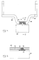
- connection 69 is arranged at the front end of the front chassis portion 61 of the rear chassis member and the other connection 72 (compare with Fig 2 and 3) is arranged at the rear end of the rear chassis portion 62 of the rear chassis member and, accordingly, the distance may be considerable between the connection 69 and 72
- the load carrier arrangement 47 is supported between the first and second connections 69, 72 with respect to the front and/or rear chassis portion 61, 72 of the rear chassis member 49 by means of support means 81.
- support means 81 is illustrated in the example as acting between the load carrier arrangement and the front chassis portion 61, but similar support means could also be arranged between the load carrier arrangement and the rear chassis portion 62.
- the support means 61 suitably consist of rollers, which may be arranged in connection with one of the embankments 64, suitably the foremost.
- These rollers 81 are in the example arranged on the load carrier arrangement so as to rolingly contact support surfaces 82 on the front chassis portion 61.
- the axes of rotation of the rollers at least substantially intersect the substantially vertical axis of rotation 70 (Fig 9) formed by the first connection 69, whereby a regular rolling contact will be established between the rollers 81 and their supporting surfaces 82.
- a condition for the function aimed at is that the hinge 63 between the front and rear chassis portions 61 and 62 of the rear chassis member 49 only allow relative movement about a substantially vertical axis and not any relative rotation about any horizontal axis. The corresponding is for the rest valid also for the hinge 50.
- the load carrier arrangement 47 will in other words be supported by the vehicle at its front and rear ends by means of the connection 69 and 72 and the support means or wheels 81 exert a bearing function against the chassis of the vehicle therebetween.
- the vehicle may for instance have tracks known per se or arbitrary ones for contact against the ground.
- the load carrier arrangement 47 may have a very varying character. It could for instance have the character of a wagon-bridge or a container or any other carrier for an arbitrary load, e.g. machine equipment, such as forestry machines etc., arranged more or less stationary thereon.
Landscapes
- Engineering & Computer Science (AREA)
- Mechanical Engineering (AREA)
- Chemical & Material Sciences (AREA)
- Combustion & Propulsion (AREA)
- Transportation (AREA)
- Life Sciences & Earth Sciences (AREA)
- Ecology (AREA)
- Forests & Forestry (AREA)
- Environmental Sciences (AREA)
- Biodiversity & Conservation Biology (AREA)
- Vehicle Body Suspensions (AREA)
- Steering-Linkage Mechanisms And Four-Wheel Steering (AREA)
- Handcart (AREA)
Claims (24)
- Eine Vorrichtung für Lastwagen mit einem Chassis (7), das ein vorderes Glied (48) mit Rädern oder Ketten (1, 2) und ein hinteres Glied (49) mit Rädern oder Ketten (3-6) umfaßt, wobei zwei Chassisglieder wechselseitig schwenkbar durch ein Gelenk (50) miteinander verbunden sind, das eine im wesentlichen vertikale Schwenkachse (51) bildet, einer Lastträgeranordnung (47), die auf dem hinteren Chassisglied (49) angeordnet ist, wobei das hintere Chassisglied (49) zwei Chassisteile (61, 62) umfaßt, nämlich ein vorderes und ein hinteres Teil, welche wechselseitig schwenkbar durch ein Gelenk (63) miteinander verbunden sind, das eine im wesentlichen vertikale Schwenkachse bildet, wobei jedes der Teile (61, 62) Räder oder Ketten (3, 4 bzw. 5, 6) aufweist,
dadurch gekennzeichnet,
daß die Räder oder Ketten (1, 2) des vorderen Chassisgliedes (48) individuell mittels eines jeweiligen vertikal schwenkbaren Schwenkarms (8, 9) aufgehängt sind, daß die Räder oder Ketten (3-6) der vorderen und hinteren Chassisteile (61, 62) des hinteren Chassisgliedes (49) individuell mittels eines jeweiligen vertikal schwenkbaren Schwenkarms (10-13) aufgehängt sind, wobei das Fahrzeug wenigstens sechs Räder oder Ketten aufweist, von denen wenigstens drei (1, 3, 5 bzw. 2, 4, 6) auf jeder Seite des Fahrzeuges angeordnet sind und von denen jedes individuell in einem Chassis (7) des Fahrzeuges mittels des jeweiligen vertikal schwenkbaren Schwenkarms (8-13) aufgehängt ist, ein Hydraulikzylinder (16-20) zwischen jedem von ihnen und dem Fahrzeugchassis angeordnet ist, jeder Zylinder zwei Hydraulikfluidräume (28-33 bzw. 34-39) aufweist, die auf gegenüberliegenden Seiten eines Kolbens des Hydraulikzylinders angeordnet sind, Hydraulikfluid in einem ersten (28-33) der Räume komprimiert wird, um einem derartigen Schwenken des entsprechenden Schwenkarmes entgegenzuwirken, damit das darauf angeordnete Rad oder die Kette bezüglich des Fahrzeugchassis angehoben wird, daß die Hydraulikzylinder (16-21) zur wechselseitigen Zusammenwirkung in einem geschlossenen Kreis gekoppelt sind, in welchem die ersten Räume (28, 30, 32 bzw. 29, 31, 33) der Zylinder der Schwenkarme (8, 10, 12 bzw. 9, 11, 13), die auf jeder Seite des Fahrzeuges angeordnet sind, miteinander kommunizieren, wobei die zweiten Hydraulikfluidräume (34, 35) der wenigstens zwei Hydraulikzylinder (16, 17) für wenigstens zwei Schwenkarme (8, 9), die auf gegenüberliegenden Seiten des Fahrzeuges dichter an dem ersten Ende (F) des Fahrzeuges als an einem zweiten Ende (B) davon angeordnet sind, miteinander kommunizieren, und die zweiten Räume (36, 38 bzw. 37, 39) der wenigstens zwei Hydraulikzylinder (18, 20 bzw. 19, 21) für die weiteren Schwenkarme (10, 13 bzw. 11, 13) auf jeder Seite des Fahrzeuges sowohl miteinander als auch mit den zweiten Räumen (37, 39 bzw. 36, 38) der wenigstens zwei Hydraulikzylinder (19, 21 bzw. 18, 20) kommunizieren, die auf gegenüberliegenden Seiten des Fahrzeuges angeordnet sind. - Eine Vorrichtung nach Anspruch 1,
dadurch gekennzeichnet,
daß die Schwenkarme (10 - 13) auf den Chassisteilen (61, 62) des hinteren Chassisgliedes im wesentlichen nach hinten gerichtet sind. - Eine Vorrichtung nach Anspruch 1 oder 2,
dadurch gekennzeichnet,
daß die Schwenkarme (8, 9) auf dem vorderen Chassisglied (48) im wesentlichen nach vorne gerichtet sind. - Eine Vorrichtung nach einem der vorhergehenden Ansprüche,
dadurch gekennzeichnet,
daß die Lastträgeranordnung (47) drehbar mit dem vorderen Chassisteil (61) des hinteren Chassisgliedes (69) mittels einer ersten Verbindung (69) verbunden ist, die eine im wesentlichen vertikale Drehachse (70) bildet. - Eine Vorrichtung nach einem der vorhergehenden Ansprüche,
dadurch gekennzeichnet,
daß die Lastträgeranordnung (47) drehbar mit dem hinteren Chassisteil (62) des hinteren Chassisgliedes (49) mittels einer zweiten Verbindung (42) verbunden ist, die eine im wesentlichen vertikale Drehachse (73) bildet. - Eine Vorrichtung nach den Ansprüchen 4 und 5,
dadurch gekennzeichnet,
daß wenigstens eine der ersten und zweiten Verbindungen so angeordnet ist, daß sie eine relative Bewegung der Lastträgeranordnung (47) und des fraglichen Chassisteils in der longitudinalen Richtung der Lastträgeranordnung oder dieses Chassisteils erlaubt. - Eine Vorrichtung nach Anspruch 6,
dadurch gekennzeichnet,
daß die eine der ersten und zweiten Verbindungen, die die relative longitudinale Bewegung erlaubt, die eine (72) zwischen der Lastträgeranordnung (47) und dem hinteren Chassisteil (62) des hinteren Chassisgliedes ist. - Eine Vorrichtung nach Anspruch 6 oder 7,
dadurch gekennzeichnet,
daß die eine (72) der ersten und zweiten Verbindungen, die die relative longitudinale Bewegung erlaubt, ein erstes Verbindungsmittel (74, 76) auf der Lastträgeranordnung und ein zweites Verbindungsmittel (75) auf dem fraglichen Chassisteil umfaßt, und daß eines der Verbindungsmittel die Form einer Führung aufweist, entlang welcher das verbleibende Verbindungsmittel verschiebbar bewegbar ist. - Eine Vorrichtung nach einem der vorhergehenden Ansprüche,
dadurch gekennzeichnet,
daß das hintere Chassisteil (62) des hinteren Chassisgliedes so angeordnet ist, daß es ein vorspringendes Teil der Lastträgeranordnung (47) von unten trägt. - Eine Vorrichtung nach einem der vorhergehenden Ansprüche,
dadurch gekennzeichnet,
daß Leistungsmittel (80) angeordnet sind, um den Schwenkwinkel zwischen den vorderen und hinteren Chassisteilen (61, 62) des hinteren Chassisgliedes zu steuern. - Eine Vorrichtung nach Anspruch 1, mit wenigstens acht Rädern oder Ketten, wobei wenigstens vier davon auf jeder Seite des Fahrzeuges angeordnet sind,
dadurch gekennzeichnet,
daß die ersten Räume (55, 28, 30, 32 bzw. 56, 29, 31, 33) der Hydraulikzylinder der Schwenkarme, die auf jeder Seite des Fahrzeuges angeordnet sind, miteinander kommunizieren, und daß die zweiten Räume (57, 34; 58, 35; 36, 38; 37, 39) ihrer Hydraulikzylinder sowohl der zwei vorderen als auch der zwei hinteren Paare von Schwenkarmen miteinander kommunizieren. - Eine Vorrichtung nach Anspruch 4,
dadurch gekennzeichnet,
daß der Lastwagen einen Ladekran (78) aufweist, welcher mit der Lastträgeranordnung (47) so verbunden ist, daß er ihrer Drehbewegung um die im wesentlichen vertikale Drehachse (70) folgt, die durch die erste Verbindung (69) zwischen der Lastträgeranordnung und dem vorderen Chassisteil (61) des hinteren Chassisgliedes (49) gebildet ist. - Eine Vorrichtung nach Anspruch 12,
dadurch gekennzeichnet,
daß der Ladekran (78) drehbar durch die Lastträgeranordnung (47) getragen ist. - Eine Vorrichtung nach Anspruch 13,
dadurch gekennzeichnet,
daß der Ladekran (78) auf dem vorderen Teil der Lastträgeranordnung (47) angeordnet ist. - Eine Vorrichtung nach einem der Ansprüche 12 bis 14,
dadurch gekennzeichnet,
daß die Lastträgeranordnung (47) Holzdämme (64) und ein Tor (66) umfaßt, und daß der Ladekran (78) drehbar durch die Lastträgeranordnung (47) mittels eines Teils (71) davon, das vor dem Tor (66) vorsteht, getragen ist. - Eine Vorrichtung nach einem der Ansprüche 1 bis 3,
dadurch gekennzeichnet,
daß die Schwenkachse (14) der Schwenkarme (10, 11) auf dem vorderen Teil (61) des hinteren Chassisgliedes (49) dicht an dem vorderen Ende des zuletzt erwähnten Chassisteils angeordnet ist. - Eine Vorrichtung nach einem der Ansprüche 1 bis 3 oder 16,
dadurch gekennzeichnet,
daß die Schwenkachse (14) der Schwenkarme (12, 13) auf dem hinteren Chassisteil (62) des hinteren Chassisgliedes bei dem vorderen Ende des hinteren Chassisteils angeordnet ist. - Eine Vorrichtung nach einem der Ansprüche 4 bis 8,
dadurch gekennzeichnet,
daß die erste Verbindung (69) dicht an dem vorderen Ende des vorderen Chassisteils (61) des hinteren Chassisgliedes angeordnet ist. - Eine Vorrichtung nach den Ansprüchen 4 und 5,
dadurch gekennzeichnet,
daß weitere Tragepunkte zwischen der Lastträgeranordnung (47) und dem vorderen Chassisteil (61) und/oder dem hinteren Chassisteil (62) zwischen den ersten und zweiten Verbindungen (69, 72) angeordnet sind. - Eine Vorrichtung nach einem der vorhergehenden Ansprüche,
dadurch gekennzeichnet,
daß die Lastträgeranordnung (47) eine starre, kontinuierliche Einheit bildet. - Eine Vorrichtung nach den Ansprüchen 4 und 5,
dadurch gekennzeichnet,
daß die Lastträgeranordnung zwischen den ersten und zweiten Verbindungen (69, 72) bezüglich des vorderen und/oder hinteren Chassisteils (61, 62) der hinteren Chassisglieder (49) mittels Tragemitteln getragen ist. - Eine Vorrichtung nach Anspruch 21,
dadurch gekennzeichnet,
daß die Tragemittel aus Rollen bestehen. - Eine Vorrichtung nach Anspruch 22,
dadurch gekennzeichnet,
daß die Rollen auf der Lastträgeranordnung angeordnet sind. - Eine Vorrichtung nach Anspruch 22 oder 23,
dadurch gekennzeichnet,
daß die Drehachsen der Rollen allgemein die im wesentlichen vertikale Drehachse (70) schneiden, die durch die erste Verbindung (69) gebildet ist.
Applications Claiming Priority (3)
| Application Number | Priority Date | Filing Date | Title |
|---|---|---|---|
| SE9000983 | 1990-03-20 | ||
| SE9000983A SE467965B (sv) | 1989-12-14 | 1990-03-20 | Anordning vid lastfordon |
| PCT/SE1991/000190 WO1991014610A1 (en) | 1990-03-20 | 1991-03-13 | A device in vehicles |
Publications (2)
| Publication Number | Publication Date |
|---|---|
| EP0551265A1 EP0551265A1 (de) | 1993-07-21 |
| EP0551265B1 true EP0551265B1 (de) | 1995-12-06 |
Family
ID=20378907
Family Applications (1)
| Application Number | Title | Priority Date | Filing Date |
|---|---|---|---|
| EP91906714A Expired - Lifetime EP0551265B1 (de) | 1990-03-20 | 1991-03-13 | Vorrichtung für fahrzeuge |
Country Status (6)
| Country | Link |
|---|---|
| US (1) | US5366337A (de) |
| EP (1) | EP0551265B1 (de) |
| CA (1) | CA2078672C (de) |
| DE (1) | DE69115285T2 (de) |
| FI (1) | FI101525B1 (de) |
| WO (1) | WO1991014610A1 (de) |
Families Citing this family (24)
| Publication number | Priority date | Publication date | Assignee | Title |
|---|---|---|---|---|
| US6016885A (en) * | 1997-08-22 | 2000-01-25 | Caterpillar Inc. | Steering system |
| DE19813278A1 (de) * | 1998-03-26 | 1999-10-07 | Teupen Maschinenbau Gmbh B | Mobile Drei-Fahrzeug-Arbeitsbühne |
| US6213490B1 (en) * | 1998-09-25 | 2001-04-10 | Case Corporation | Work vehicle with nested steering |
| US6206118B1 (en) * | 1998-09-25 | 2001-03-27 | Case Corporation | Articulated work vehicle |
| CA2307926C (en) * | 2000-05-09 | 2002-06-11 | Degelman Industries Lp | Multi-functional self-propelled farm tractor |
| EP1330385B1 (de) * | 2000-10-30 | 2005-12-28 | John Deere Forestry Oy | Fahrgestellkonstruktion für eine waldarbeitsmaschine |
| US6299181B1 (en) * | 2000-12-07 | 2001-10-09 | Caterpillar S.A.R.L. | Vehicle having steerable wheels |
| US20040197181A1 (en) * | 2001-08-03 | 2004-10-07 | Clark Curtis C. | Mobile load handling apparatus |
| SE0102772D0 (sv) * | 2001-08-21 | 2001-08-21 | Fiberpac Ab | Skogsmaskin |
| FI115513B (fi) * | 2001-08-30 | 2005-05-31 | Timberjack Oy | Työkoneen kuormatilan pinta-alan muuttaminen |
| FR2833561B1 (fr) * | 2001-12-13 | 2004-02-13 | Olivier Bonnefond | Porte-outils pour culture en lignes |
| FI111350B (fi) | 2002-01-16 | 2003-07-15 | Timberjack Oy | Työkoneen kuormatilan dimensioiden muuttaminen |
| FI117624B (fi) | 2003-01-24 | 2006-12-29 | John Deere Forestry Oy | Metsätyökoneen nosturin ohjaaminen ajon aikana |
| CA2582004C (en) * | 2003-10-01 | 2013-02-19 | Technology Investments Limited | Articulated dump truck |
| CA2463044A1 (en) * | 2004-04-02 | 2005-10-02 | H. William B. Wilt | Method of making a modular vehicle and a modular vehicle |
| ES2277525B1 (es) * | 2005-07-14 | 2008-05-16 | William M.C. Rendall | Uso de cabina perfeccionada para vehiculos acoplables. |
| US7828328B2 (en) * | 2008-10-29 | 2010-11-09 | Caterpillar Forest Products Inc | System and method for a forwarder headboard |
| US8191928B2 (en) * | 2008-10-29 | 2012-06-05 | Caterpillar Forest Products Inc. | Stabilizing assembly for a forwarder headboard and method |
| CA2869034C (en) | 2012-03-30 | 2020-04-28 | T&T Engineering Services, Inc. | Mechanically steered articulating dolly transport system |
| FI124889B (fi) * | 2012-05-31 | 2015-03-13 | Ponsse Oyj | Sovitelma metsäkoneessa ja vastaavalla sovitelmalla varustettu metsäkone |
| RU2661185C1 (ru) * | 2017-04-24 | 2018-07-12 | Федеральное государственное бюджетное учреждение "3 Центральный научно-исследовательский институт" Министерства обороны Российской Федерации | Полноприводное модульное транспортное средство |
| SE542937C2 (en) | 2018-12-21 | 2020-09-15 | Eco Log Sweden Ab | Forestry vehicle comprising idler wheel and drive wheel arranged on a pivotable arm |
| RU2726987C1 (ru) * | 2019-12-31 | 2020-07-17 | Федеральное государственное бюджетное образовательное учреждение высшего образования "Воронежский государственный лесотехнический университет имени Г.Ф. Морозова" | Рекуперативный гидропривод лесовозного тягача с полуприцепом |
| AT526150B1 (de) * | 2022-10-03 | 2023-12-15 | Konrad Forsttechnik Gmbh | Vorrichtung und Verfahren zum Transportieren von Holz in steilem Gelände |
Family Cites Families (6)
| Publication number | Priority date | Publication date | Assignee | Title |
|---|---|---|---|---|
| SE327631B (de) * | 1965-09-20 | 1970-08-24 | Kockums Mekaniska Verkstads Ab | |
| YU31878B (en) * | 1968-12-02 | 1973-12-31 | Interprinderea Montaje Conduct | Prikolica sa uredjajem za rukovanje i transport dugih predmeta |
| FI64085C (fi) * | 1977-10-21 | 1983-10-10 | Konetehdas Norcar | Anordning vid dragbom foer slaepvagn |
| FI60832C (fi) * | 1978-09-12 | 1982-04-13 | Orvo Kalevi Naamanka | Terraengfordon |
| FI79676C (fi) * | 1985-12-03 | 1990-02-12 | Nokka Forest Oy | Styrsystem foer paohaengsvagn till terraengfordon. |
| FI83192C (fi) * | 1988-09-12 | 1991-06-10 | Lasse Karilainen | Kraftoeverfoerings- och ledsystem mellan ett terraengfordon och en slaepvagn. |
-
1991
- 1991-03-13 EP EP91906714A patent/EP0551265B1/de not_active Expired - Lifetime
- 1991-03-13 WO PCT/SE1991/000190 patent/WO1991014610A1/en not_active Ceased
- 1991-03-13 CA CA002078672A patent/CA2078672C/en not_active Expired - Lifetime
- 1991-03-13 DE DE69115285T patent/DE69115285T2/de not_active Expired - Fee Related
- 1991-03-13 US US07/949,527 patent/US5366337A/en not_active Expired - Fee Related
-
1992
- 1992-09-18 FI FI924202A patent/FI101525B1/fi active
Also Published As
| Publication number | Publication date |
|---|---|
| US5366337A (en) | 1994-11-22 |
| FI101525B (fi) | 1998-07-15 |
| DE69115285D1 (de) | 1996-01-18 |
| FI101525B1 (fi) | 1998-07-15 |
| WO1991014610A1 (en) | 1991-10-03 |
| DE69115285T2 (de) | 1996-07-18 |
| EP0551265A1 (de) | 1993-07-21 |
| FI924202L (fi) | 1992-09-18 |
| CA2078672A1 (en) | 1991-09-21 |
| FI924202A0 (fi) | 1992-09-18 |
| CA2078672C (en) | 2002-05-14 |
Similar Documents
| Publication | Publication Date | Title |
|---|---|---|
| US5366337A (en) | Articulated load carrier for vehicles | |
| US4410207A (en) | Bumper structure for vehicle having tiltable load carrier member | |
| US4580797A (en) | Device at cross-country vehicles or machines | |
| US3704896A (en) | Auxiliary steerable wheels for vehicles | |
| US4502709A (en) | Articulated loader with transversely displaceable counterweight | |
| SU1347869A3 (ru) | Передвижна врубова машина | |
| WO1989000928A1 (en) | Cross-country vehicle | |
| US3881427A (en) | Monorail car and wheel assembly | |
| US20070262552A1 (en) | Suspension system for a transport vehicle | |
| US7040428B2 (en) | Chassis structure for a forest machine | |
| US3591195A (en) | Wheel assembly for vehicles particularly intended for combined road and cross-country transports | |
| WO1992010390A1 (en) | A device in vehicles | |
| US5044858A (en) | Vehicle with lateral moving lift | |
| US7077412B2 (en) | Suspension of wheels in a working machine | |
| US3016987A (en) | Pivoted vehicle steering mechanism | |
| US3450222A (en) | Self-propelled vehicle having three-wheeled sections | |
| US2187197A (en) | Industrial truck | |
| US4940110A (en) | Mobile work unit with raisable and lowerable support legs | |
| US6123499A (en) | Recovery vehicle | |
| US5988309A (en) | Frame assembly for an articulated construction machine | |
| US4154456A (en) | Articulated vehicle with movable joint | |
| US3397752A (en) | Articulated frame steer tractor | |
| EP0934864A1 (de) | Fahrzeug mit lenkbarer Hinterachse | |
| SE467965B (sv) | Anordning vid lastfordon | |
| GB2161434A (en) | Articulated vehicles |
Legal Events
| Date | Code | Title | Description |
|---|---|---|---|
| PUAI | Public reference made under article 153(3) epc to a published international application that has entered the european phase |
Free format text: ORIGINAL CODE: 0009012 |
|
| 17P | Request for examination filed |
Effective date: 19921021 |
|
| AK | Designated contracting states |
Kind code of ref document: A1 Designated state(s): BE DE DK ES FR GB SE |
|
| 17Q | First examination report despatched |
Effective date: 19940615 |
|
| GRAA | (expected) grant |
Free format text: ORIGINAL CODE: 0009210 |
|
| AK | Designated contracting states |
Kind code of ref document: B1 Designated state(s): BE DE DK ES FR GB SE |
|
| PG25 | Lapsed in a contracting state [announced via postgrant information from national office to epo] |
Ref country code: BE Effective date: 19951206 Ref country code: ES Free format text: THE PATENT HAS BEEN ANNULLED BY A DECISION OF A NATIONAL AUTHORITY Effective date: 19951206 Ref country code: DK Effective date: 19951206 |
|
| REF | Corresponds to: |
Ref document number: 69115285 Country of ref document: DE Date of ref document: 19960118 |
|
| ET | Fr: translation filed | ||
| PLBE | No opposition filed within time limit |
Free format text: ORIGINAL CODE: 0009261 |
|
| STAA | Information on the status of an ep patent application or granted ep patent |
Free format text: STATUS: NO OPPOSITION FILED WITHIN TIME LIMIT |
|
| 26N | No opposition filed | ||
| REG | Reference to a national code |
Ref country code: GB Ref legal event code: 732E |
|
| REG | Reference to a national code |
Ref country code: FR Ref legal event code: TP |
|
| REG | Reference to a national code |
Ref country code: GB Ref legal event code: 732E |
|
| REG | Reference to a national code |
Ref country code: FR Ref legal event code: TP |
|
| REG | Reference to a national code |
Ref country code: GB Ref legal event code: IF02 |
|
| PGFP | Annual fee paid to national office [announced via postgrant information from national office to epo] |
Ref country code: GB Payment date: 20030204 Year of fee payment: 13 |
|
| PGFP | Annual fee paid to national office [announced via postgrant information from national office to epo] |
Ref country code: FR Payment date: 20030303 Year of fee payment: 13 |
|
| PG25 | Lapsed in a contracting state [announced via postgrant information from national office to epo] |
Ref country code: GB Free format text: LAPSE BECAUSE OF NON-PAYMENT OF DUE FEES Effective date: 20040313 |
|
| GBPC | Gb: european patent ceased through non-payment of renewal fee |
Effective date: 20040313 |
|
| PG25 | Lapsed in a contracting state [announced via postgrant information from national office to epo] |
Ref country code: FR Free format text: LAPSE BECAUSE OF NON-PAYMENT OF DUE FEES Effective date: 20041130 |
|
| REG | Reference to a national code |
Ref country code: FR Ref legal event code: ST |
|
| PGFP | Annual fee paid to national office [announced via postgrant information from national office to epo] |
Ref country code: DE Payment date: 20090331 Year of fee payment: 19 Ref country code: SE Payment date: 20090306 Year of fee payment: 19 |
|
| EUG | Se: european patent has lapsed | ||
| PG25 | Lapsed in a contracting state [announced via postgrant information from national office to epo] |
Ref country code: DE Free format text: LAPSE BECAUSE OF NON-PAYMENT OF DUE FEES Effective date: 20101001 |
|
| PG25 | Lapsed in a contracting state [announced via postgrant information from national office to epo] |
Ref country code: SE Free format text: LAPSE BECAUSE OF NON-PAYMENT OF DUE FEES Effective date: 20100314 |