EP0551538A1 - Amplificateur de charge - Google Patents
Amplificateur de charge Download PDFInfo
- Publication number
- EP0551538A1 EP0551538A1 EP92100530A EP92100530A EP0551538A1 EP 0551538 A1 EP0551538 A1 EP 0551538A1 EP 92100530 A EP92100530 A EP 92100530A EP 92100530 A EP92100530 A EP 92100530A EP 0551538 A1 EP0551538 A1 EP 0551538A1
- Authority
- EP
- European Patent Office
- Prior art keywords
- voltage
- current
- integrator
- charge amplifier
- charge
- Prior art date
- Legal status (The legal status is an assumption and is not a legal conclusion. Google has not performed a legal analysis and makes no representation as to the accuracy of the status listed.)
- Granted
Links
- 239000003990 capacitor Substances 0.000 claims description 10
- 230000010354 integration Effects 0.000 claims description 8
- 238000002485 combustion reaction Methods 0.000 abstract description 7
- 238000005259 measurement Methods 0.000 abstract description 2
- 239000000919 ceramic Substances 0.000 abstract 1
- 238000010586 diagram Methods 0.000 description 4
- 230000003321 amplification Effects 0.000 description 1
- 239000003985 ceramic capacitor Substances 0.000 description 1
- 238000001514 detection method Methods 0.000 description 1
- 239000011888 foil Substances 0.000 description 1
- 238000000034 method Methods 0.000 description 1
- 238000003199 nucleic acid amplification method Methods 0.000 description 1
- 238000009738 saturating Methods 0.000 description 1
Images
Classifications
-
- G—PHYSICS
- G01—MEASURING; TESTING
- G01L—MEASURING FORCE, STRESS, TORQUE, WORK, MECHANICAL POWER, MECHANICAL EFFICIENCY, OR FLUID PRESSURE
- G01L1/00—Measuring force or stress, in general
- G01L1/16—Measuring force or stress, in general using properties of piezoelectric devices
-
- G—PHYSICS
- G01—MEASURING; TESTING
- G01L—MEASURING FORCE, STRESS, TORQUE, WORK, MECHANICAL POWER, MECHANICAL EFFICIENCY, OR FLUID PRESSURE
- G01L23/00—Devices or apparatus for measuring or indicating or recording rapid changes, such as oscillations, in the pressure of steam, gas, or liquid; Indicators for determining work or energy of steam, internal-combustion, or other fluid-pressure engines from the condition of the working fluid
- G01L23/08—Devices or apparatus for measuring or indicating or recording rapid changes, such as oscillations, in the pressure of steam, gas, or liquid; Indicators for determining work or energy of steam, internal-combustion, or other fluid-pressure engines from the condition of the working fluid operated electrically
- G01L23/10—Devices or apparatus for measuring or indicating or recording rapid changes, such as oscillations, in the pressure of steam, gas, or liquid; Indicators for determining work or energy of steam, internal-combustion, or other fluid-pressure engines from the condition of the working fluid operated electrically by pressure-sensitive members of the piezoelectric type
-
- G—PHYSICS
- G01—MEASURING; TESTING
- G01L—MEASURING FORCE, STRESS, TORQUE, WORK, MECHANICAL POWER, MECHANICAL EFFICIENCY, OR FLUID PRESSURE
- G01L23/00—Devices or apparatus for measuring or indicating or recording rapid changes, such as oscillations, in the pressure of steam, gas, or liquid; Indicators for determining work or energy of steam, internal-combustion, or other fluid-pressure engines from the condition of the working fluid
- G01L23/22—Devices or apparatus for measuring or indicating or recording rapid changes, such as oscillations, in the pressure of steam, gas, or liquid; Indicators for determining work or energy of steam, internal-combustion, or other fluid-pressure engines from the condition of the working fluid for detecting or indicating knocks in internal-combustion engines; Units comprising pressure-sensitive members combined with ignitors for firing internal-combustion engines
- G01L23/221—Devices or apparatus for measuring or indicating or recording rapid changes, such as oscillations, in the pressure of steam, gas, or liquid; Indicators for determining work or energy of steam, internal-combustion, or other fluid-pressure engines from the condition of the working fluid for detecting or indicating knocks in internal-combustion engines; Units comprising pressure-sensitive members combined with ignitors for firing internal-combustion engines for detecting or indicating knocks in internal combustion engines
- G01L23/222—Devices or apparatus for measuring or indicating or recording rapid changes, such as oscillations, in the pressure of steam, gas, or liquid; Indicators for determining work or energy of steam, internal-combustion, or other fluid-pressure engines from the condition of the working fluid for detecting or indicating knocks in internal-combustion engines; Units comprising pressure-sensitive members combined with ignitors for firing internal-combustion engines for detecting or indicating knocks in internal combustion engines using piezoelectric devices
-
- G—PHYSICS
- G01—MEASURING; TESTING
- G01L—MEASURING FORCE, STRESS, TORQUE, WORK, MECHANICAL POWER, MECHANICAL EFFICIENCY, OR FLUID PRESSURE
- G01L23/00—Devices or apparatus for measuring or indicating or recording rapid changes, such as oscillations, in the pressure of steam, gas, or liquid; Indicators for determining work or energy of steam, internal-combustion, or other fluid-pressure engines from the condition of the working fluid
- G01L23/22—Devices or apparatus for measuring or indicating or recording rapid changes, such as oscillations, in the pressure of steam, gas, or liquid; Indicators for determining work or energy of steam, internal-combustion, or other fluid-pressure engines from the condition of the working fluid for detecting or indicating knocks in internal-combustion engines; Units comprising pressure-sensitive members combined with ignitors for firing internal-combustion engines
- G01L23/221—Devices or apparatus for measuring or indicating or recording rapid changes, such as oscillations, in the pressure of steam, gas, or liquid; Indicators for determining work or energy of steam, internal-combustion, or other fluid-pressure engines from the condition of the working fluid for detecting or indicating knocks in internal-combustion engines; Units comprising pressure-sensitive members combined with ignitors for firing internal-combustion engines for detecting or indicating knocks in internal combustion engines
- G01L23/225—Devices or apparatus for measuring or indicating or recording rapid changes, such as oscillations, in the pressure of steam, gas, or liquid; Indicators for determining work or energy of steam, internal-combustion, or other fluid-pressure engines from the condition of the working fluid for detecting or indicating knocks in internal-combustion engines; Units comprising pressure-sensitive members combined with ignitors for firing internal-combustion engines for detecting or indicating knocks in internal combustion engines circuit arrangements therefor
-
- G—PHYSICS
- G01—MEASURING; TESTING
- G01L—MEASURING FORCE, STRESS, TORQUE, WORK, MECHANICAL POWER, MECHANICAL EFFICIENCY, OR FLUID PRESSURE
- G01L9/00—Measuring steady of quasi-steady pressure of fluid or fluent solid material by electric or magnetic pressure-sensitive elements; Transmitting or indicating the displacement of mechanical pressure-sensitive elements, used to measure the steady or quasi-steady pressure of a fluid or fluent solid material, by electric or magnetic means
- G01L9/08—Measuring steady of quasi-steady pressure of fluid or fluent solid material by electric or magnetic pressure-sensitive elements; Transmitting or indicating the displacement of mechanical pressure-sensitive elements, used to measure the steady or quasi-steady pressure of a fluid or fluent solid material, by electric or magnetic means by making use of piezoelectric devices, i.e. electric circuits therefor
- G01L9/085—Measuring steady of quasi-steady pressure of fluid or fluent solid material by electric or magnetic pressure-sensitive elements; Transmitting or indicating the displacement of mechanical pressure-sensitive elements, used to measure the steady or quasi-steady pressure of a fluid or fluent solid material, by electric or magnetic means by making use of piezoelectric devices, i.e. electric circuits therefor with temperature compensating means
Definitions
- the invention relates to a charge amplifier according to the preamble of claim 1.
- Piezoceramic sensors which are mounted between the spark plug and the cylinder head or fastened in an indexing hole in the cylinder head, are directly exposed to the combustion chamber pressure. These sensors emit a charge signal that is proportional to the pressure curve in the cylinder.
- the charge signal supplied by the sensor is amplified by means of a charge amplifier and converted into a voltage signal.
- a charge amplifier is ideally a current integrator.
- Piezoceramic and other sensors that emit electrical charge have properties that impair the proportionality between the measured variable (combustion chamber pressure) and the sensor signal.
- the drift of the charge signal over the temperature caused by the sensor - e.g. caused by sudden load changes of the internal combustion engine - ensures a strong restriction of the useful signal range within the supply voltage range.
- the current frequency response (interference frequency response) of the charge amplifier leads to a high DC component in the output signal (hysteresis of the temperature-related signal drift).
- FIG. 1 Known charge amplifiers (FIG. 1) are operated in practice with a resistor connected in parallel with the integration capacitor. Because of the resulting high pass 1st order in the charge frequency response prevents the charge amplifier from saturating within a short time due to constantly integrated leakage currents.
- the current frequency response corresponds to a low-pass filter of the 1st order, which means that temperature errors are not damped at all.
- the object of the invention is to provide a charge amplifier in which the temperature drift and the hysteresis are significantly lower and which does not tend to oscillate.
- the resulting circuit structure results in a division into a stable current / voltage converter, which is advantageously designed as a current amplifier, and into a voltage integrator, in which the parallel resistor connected to an output voltage divider to the integration capacitor can have a relatively low value, which is a constant requirement when used in motor vehicles (integration capability, leakage currents).
- the circuit also offers great advantages in signal processing.
- the integrator in the negative feedback branch leads to a charge frequency response which represents a second-order high-pass filter. Temperature gradient errors of the sensor are suppressed twice as well as in the known charge amplifier, as are other temperature-related effects. The output voltage drift when the load changes is only half as large.
- the current frequency response exhibits bandpass behavior, which completely suppresses the hysteresis errors. This shows the Sensor apparently no longer has a hysteresis effect of the output signal drifting when the load changes.
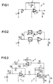
- FIG. 1 shows the circuit of a known charge amplifier using discrete technology, consisting of an operational amplifier OP connected as an integrator 3, the integration capacitor C of which is connected in parallel with a resistor R and which fulfills the function of a current integrator with charge amplification. Its advantages and disadvantages have already been mentioned above.
- This charge amplifier converts that from a piezoceramic Sensor 1 received charge signal Qe into an output signal Ua that is as proportional as possible.
- FIG. 2 shows a basic circuit diagram of a charge amplifier according to the invention.
- This circuit diagram shows the individual functions and is therefore advantageous because exemplary embodiments in different techniques, for example an integrated solution, can differ considerably in the execution of the individual functional blocks from the exemplary embodiment shown in FIG. 3 and implemented using discrete technology.
- the output signal of the piezoceramic sensor 1, the charge Qe, or the sensor current Is, is converted into a voltage signal in a current / voltage converter 2 and this is converted into the output signal Ua in a subsequent voltage integrator 3.
- This output signal Ua is fed back from the output of the voltage integrator 3 via an integrator 4 and a voltage / current converter 5 to the input of the current / voltage converter.
- FIG 3 finally shows an embodiment of a charge amplifier according to the invention according to the basic circuit diagram in Figure 2, but in discrete technology, carried out with operational amplifiers.
- the current / voltage converter 2 is designed as a current amplifier from an operational amplifier OP1 connected to a resistor R1, which converts the input signal Qe or Is of the piezoceramic sensor 1 into a voltage signal, which is generated by the subsequent voltage integrator 3, consisting of a Operational amplifier OP2, connected to an input resistor R2 and a negative feedback integration capacitor C1 with a resistor R5 connected in parallel via an output voltage divider R3, R4, is integrated into the output signal Ua.
- This signal is then processed in a manner not shown, for example to produce pressure and / or knock signals.
- the output signal Ua is integrated into a voltage signal Ug via a further voltage integrator 4, consisting of an operational amplifier OP3 connected to an input resistor R6 and an integration capacitor C2 - this time without a parallel resistor - and this then via a voltage / current formed by a resistor R7 Converter 5 converted into a current signal Ig, which is superimposed on the output signal Is of the sensor 1.
- a further voltage integrator 4 consisting of an operational amplifier OP3 connected to an input resistor R6 and an integration capacitor C2 - this time without a parallel resistor - and this then via a voltage / current formed by a resistor R7 Converter 5 converted into a current signal Ig, which is superimposed on the output signal Is of the sensor 1.
- the negative feedback integrator 4 including the resistor R6, which, like the resistor R7, is relatively high-resistance in discrete technology, can be implemented with current source circuits, so that these two resistors do not have to be integrated in a high-resistance manner.
Landscapes
- Chemical & Material Sciences (AREA)
- Engineering & Computer Science (AREA)
- Combustion & Propulsion (AREA)
- Physics & Mathematics (AREA)
- General Physics & Mathematics (AREA)
- Measuring Fluid Pressure (AREA)
- Amplifiers (AREA)
Priority Applications (4)
| Application Number | Priority Date | Filing Date | Title |
|---|---|---|---|
| EP92100530A EP0551538B1 (fr) | 1992-01-14 | 1992-01-14 | Amplificateur de charge |
| DE59205962T DE59205962D1 (de) | 1992-01-14 | 1992-01-14 | Ladungsverstärker |
| JP5019194A JPH05267958A (ja) | 1992-01-14 | 1993-01-12 | 電荷信号増幅器 |
| US08/004,415 US5371472A (en) | 1992-01-14 | 1993-01-14 | Charge amplifier for sensors outputting electrical charge |
Applications Claiming Priority (1)
| Application Number | Priority Date | Filing Date | Title |
|---|---|---|---|
| EP92100530A EP0551538B1 (fr) | 1992-01-14 | 1992-01-14 | Amplificateur de charge |
Publications (2)
| Publication Number | Publication Date |
|---|---|
| EP0551538A1 true EP0551538A1 (fr) | 1993-07-21 |
| EP0551538B1 EP0551538B1 (fr) | 1996-04-10 |
Family
ID=8209239
Family Applications (1)
| Application Number | Title | Priority Date | Filing Date |
|---|---|---|---|
| EP92100530A Expired - Lifetime EP0551538B1 (fr) | 1992-01-14 | 1992-01-14 | Amplificateur de charge |
Country Status (4)
| Country | Link |
|---|---|
| US (1) | US5371472A (fr) |
| EP (1) | EP0551538B1 (fr) |
| JP (1) | JPH05267958A (fr) |
| DE (1) | DE59205962D1 (fr) |
Families Citing this family (15)
| Publication number | Priority date | Publication date | Assignee | Title |
|---|---|---|---|---|
| JPH07167661A (ja) * | 1993-12-14 | 1995-07-04 | Murata Mfg Co Ltd | 振動ジャイロ |
| US6204715B1 (en) | 1999-02-26 | 2001-03-20 | General Motors Corporation | Signal amplifying circuit |
| JP3551893B2 (ja) * | 2000-04-25 | 2004-08-11 | 株式会社村田製作所 | 電荷型センサ用増幅回路 |
| DE10026436A1 (de) * | 2000-05-29 | 2001-12-06 | Bircher Ag Beringen | Verfahren zum Bestimmen von Signalen |
| US6617764B2 (en) | 2000-09-13 | 2003-09-09 | University Of Dayton | High temperature piezoelectric sensor |
| US6454024B1 (en) * | 2000-10-27 | 2002-09-24 | Alan L. Nackerud | Replaceable drill bit assembly |
| EP1273922B1 (fr) * | 2001-07-06 | 2007-05-23 | Max-Planck-Gesellschaft zur Förderung der Wissenschaften e.V. | Appareil et procédé de mesure de courant |
| RU2219651C2 (ru) * | 2002-02-15 | 2003-12-20 | Государственное унитарное предприятие "Научно-производственное предприятие "Пульсар" | Зарядочувствительный усилитель |
| JP4309158B2 (ja) * | 2003-03-19 | 2009-08-05 | 富士重工業株式会社 | 電荷信号変換アンプ、及び筒内圧測定装置 |
| DE102005006806A1 (de) * | 2004-09-01 | 2006-03-30 | Priamus System Technologies Ag | Verfahren und Vorrichtung zum Messen von physikalischer Grössen mit piezoelektrischen Sensoren |
| DE102005006666A1 (de) * | 2005-02-14 | 2006-08-24 | Fraunhofer-Gesellschaft zur Förderung der angewandten Forschung e.V. | Piezoelektrischer Sensor und dessen Verwendung |
| RU2370880C1 (ru) * | 2008-07-31 | 2009-10-20 | Общество С Ограниченной Ответственностью "Диамех 2000" | Дифференциальный усилитель заряда для пьезодатчика (варианты) |
| RU2370882C1 (ru) * | 2008-07-31 | 2009-10-20 | Общество С Ограниченной Ответственностью "Диамех 2000" | Усилитель заряда для пьезодатчика (варианты) |
| RU2370881C1 (ru) * | 2008-07-31 | 2009-10-20 | Общество С Ограниченной Ответственностью "Диамех 2000" | Симметричный усилитель заряда для пьезодатчика (варианты) |
| JP2020084804A (ja) * | 2018-11-19 | 2020-06-04 | 株式会社ミクニ | 圧力検出信号処理装置、エンジン制御システム、および、プログラム |
Citations (3)
| Publication number | Priority date | Publication date | Assignee | Title |
|---|---|---|---|---|
| US4398104A (en) * | 1980-09-30 | 1983-08-09 | Garrett Electronics | Low drift tuning circuit |
| US4543536A (en) * | 1984-03-22 | 1985-09-24 | Fisher Controls International, Inc. | Charge amplifier with automatic zero |
| EP0253016A1 (fr) * | 1986-07-18 | 1988-01-20 | Kistler Instrumente AG | Circuit amplificateur de charge |
Family Cites Families (1)
| Publication number | Priority date | Publication date | Assignee | Title |
|---|---|---|---|---|
| JPS5292460A (en) * | 1976-01-29 | 1977-08-03 | Yokogawa Hokushin Electric Corp | Charge amplifier |
-
1992
- 1992-01-14 EP EP92100530A patent/EP0551538B1/fr not_active Expired - Lifetime
- 1992-01-14 DE DE59205962T patent/DE59205962D1/de not_active Expired - Fee Related
-
1993
- 1993-01-12 JP JP5019194A patent/JPH05267958A/ja not_active Withdrawn
- 1993-01-14 US US08/004,415 patent/US5371472A/en not_active Expired - Fee Related
Patent Citations (3)
| Publication number | Priority date | Publication date | Assignee | Title |
|---|---|---|---|---|
| US4398104A (en) * | 1980-09-30 | 1983-08-09 | Garrett Electronics | Low drift tuning circuit |
| US4543536A (en) * | 1984-03-22 | 1985-09-24 | Fisher Controls International, Inc. | Charge amplifier with automatic zero |
| EP0253016A1 (fr) * | 1986-07-18 | 1988-01-20 | Kistler Instrumente AG | Circuit amplificateur de charge |
Non-Patent Citations (3)
| Title |
|---|
| I.E.E. PROCEEDINGS SECTIONS A a I Band 130, Nr. 3, Teil G, Juni 1983, Seiten 94-96, Old Woking, GB; DINIZ et al.: "High-performance integrators and applications in 2-integrator loop biquads" * |
| MEASUREMENT TECHNIQUES Band 28, August 1985, Seiten 755,756, New York, US; ANSO: "Differentiating Integrators with Automatic Compensation of DC Input-Current Component" * |
| PATENT ABSTRACTS OF JAPAN Band 1, Nr. 152 (E-77)(7950), 7. Dezember 1977; & JP - A - 5292460 (YOKOGAWA DENKI SEISA KUSHO) 08.03.1977 * |
Also Published As
| Publication number | Publication date |
|---|---|
| DE59205962D1 (de) | 1996-05-15 |
| US5371472A (en) | 1994-12-06 |
| EP0551538B1 (fr) | 1996-04-10 |
| JPH05267958A (ja) | 1993-10-15 |
Similar Documents
| Publication | Publication Date | Title |
|---|---|---|
| EP0551538B1 (fr) | Amplificateur de charge | |
| DE3708210C2 (fr) | ||
| DE69804298T2 (de) | Signalformgeber für drehmomentsensor | |
| DE19601353A1 (de) | Verbrennungszustandsdetektor für eine Brennkraftmaschine mit innerer Verbrennung | |
| DE102005028507B3 (de) | Verfahren zur Kapazitäts-Spannungs-Wandlung und Kapazitäts-Spannungs-Wandler | |
| DE68905913T2 (de) | Beschleunigungsmessaufnehmer. | |
| DE4400437A1 (de) | Halbleitersensorvorrichtung | |
| EP0457868B1 (fr) | Dispositif pour le traitement de signaux d'un detecteur | |
| EP0376024A2 (fr) | Procédé et dispositif de correction des tolérances de manufacture des éléments d'un circuit de traitement de signaux | |
| DE19506134B4 (de) | Ladungsverstärker | |
| EP0021340B1 (fr) | Appareil pour la mesure et l'évaluation de valeurs de pointe d'un signal de tnesion pulsant | |
| EP0280261A2 (fr) | Circuit pour la production d'un signal carré indépendant de la température à une grandeur mesurée | |
| EP0357591B1 (fr) | Circuit amplificateur de charge | |
| DE2905463C2 (fr) | ||
| DE4341390A1 (de) | Schaltung zur Aufbereitung des Signals eines Meßfühlers | |
| DE4042600C3 (de) | Piezoelektrischer Beschleunigungsmesser | |
| DE2130634C3 (de) | Anordnung zur Kompensation des Einflusses äußerer und/oder innerer Störgrößen auf das Ausgangssignal eines Meßorgans | |
| DE2845728A1 (de) | Einrichtung zur verstaerkung einer impulsspannung mit driftkorrektur | |
| DE10018650A1 (de) | Auswerteschaltung für einen Sensor | |
| DE3824267C2 (fr) | ||
| EP0309451B1 (fr) | Dispositif de protection contre les signaux parasites | |
| DE3511966C2 (de) | Stromregelung für einen elektromagnetischen Verbraucher in Verbindung mit einer Brennkraftmaschine | |
| DE2550936C3 (de) | Zur kapazitiven Füllstandsmessung eines Behälters verwendete Schaltungsanordnung | |
| DE4041621A1 (de) | Auswerteschaltung fuer einen piezoresistiven drucksensor | |
| DE1762912C (de) | Schaltungsanordnung zur Wiedereinführung des Gleichspannungswertes in Fernsehsignale u.dgl. (Klemmschaltung) |
Legal Events
| Date | Code | Title | Description |
|---|---|---|---|
| PUAI | Public reference made under article 153(3) epc to a published international application that has entered the european phase |
Free format text: ORIGINAL CODE: 0009012 |
|
| AK | Designated contracting states |
Kind code of ref document: A1 Designated state(s): AT BE CH DE DK ES FR GB GR IT LI LU MC NL PT SE |
|
| RBV | Designated contracting states (corrected) |
Designated state(s): DE FR GB IT |
|
| 17P | Request for examination filed |
Effective date: 19930819 |
|
| 17Q | First examination report despatched |
Effective date: 19950721 |
|
| GRAA | (expected) grant |
Free format text: ORIGINAL CODE: 0009210 |
|
| AK | Designated contracting states |
Kind code of ref document: B1 Designated state(s): DE FR GB IT |
|
| ET | Fr: translation filed | ||
| REF | Corresponds to: |
Ref document number: 59205962 Country of ref document: DE Date of ref document: 19960515 |
|
| ITF | It: translation for a ep patent filed | ||
| GBT | Gb: translation of ep patent filed (gb section 77(6)(a)/1977) |
Effective date: 19960614 |
|
| PGFP | Annual fee paid to national office [announced via postgrant information from national office to epo] |
Ref country code: GB Payment date: 19961219 Year of fee payment: 6 |
|
| PGFP | Annual fee paid to national office [announced via postgrant information from national office to epo] |
Ref country code: FR Payment date: 19970123 Year of fee payment: 6 |
|
| PLBE | No opposition filed within time limit |
Free format text: ORIGINAL CODE: 0009261 |
|
| STAA | Information on the status of an ep patent application or granted ep patent |
Free format text: STATUS: NO OPPOSITION FILED WITHIN TIME LIMIT |
|
| PGFP | Annual fee paid to national office [announced via postgrant information from national office to epo] |
Ref country code: DE Payment date: 19970317 Year of fee payment: 6 |
|
| 26N | No opposition filed | ||
| PG25 | Lapsed in a contracting state [announced via postgrant information from national office to epo] |
Ref country code: GB Free format text: LAPSE BECAUSE OF NON-PAYMENT OF DUE FEES Effective date: 19980114 |
|
| PG25 | Lapsed in a contracting state [announced via postgrant information from national office to epo] |
Ref country code: FR Free format text: THE PATENT HAS BEEN ANNULLED BY A DECISION OF A NATIONAL AUTHORITY Effective date: 19980131 |
|
| GBPC | Gb: european patent ceased through non-payment of renewal fee |
Effective date: 19980114 |
|
| PG25 | Lapsed in a contracting state [announced via postgrant information from national office to epo] |
Ref country code: DE Free format text: LAPSE BECAUSE OF NON-PAYMENT OF DUE FEES Effective date: 19981001 |
|
| REG | Reference to a national code |
Ref country code: FR Ref legal event code: ST |
|
| PG25 | Lapsed in a contracting state [announced via postgrant information from national office to epo] |
Ref country code: IT Free format text: LAPSE BECAUSE OF NON-PAYMENT OF DUE FEES;WARNING: LAPSES OF ITALIAN PATENTS WITH EFFECTIVE DATE BEFORE 2007 MAY HAVE OCCURRED AT ANY TIME BEFORE 2007. THE CORRECT EFFECTIVE DATE MAY BE DIFFERENT FROM THE ONE RECORDED. Effective date: 20050114 |