EP0551623B1 - Soupape hydraulique avec modulation axiale - Google Patents
Soupape hydraulique avec modulation axiale Download PDFInfo
- Publication number
- EP0551623B1 EP0551623B1 EP19920121336 EP92121336A EP0551623B1 EP 0551623 B1 EP0551623 B1 EP 0551623B1 EP 19920121336 EP19920121336 EP 19920121336 EP 92121336 A EP92121336 A EP 92121336A EP 0551623 B1 EP0551623 B1 EP 0551623B1
- Authority
- EP
- European Patent Office
- Prior art keywords
- fluid
- follow
- valve member
- controller
- port
- Prior art date
- Legal status (The legal status is an assumption and is not a legal conclusion. Google has not performed a legal analysis and makes no representation as to the accuracy of the status listed.)
- Expired - Lifetime
Links
- 239000012530 fluid Substances 0.000 title claims description 177
- 230000007935 neutral effect Effects 0.000 claims description 41
- 238000004891 communication Methods 0.000 claims description 34
- 238000006073 displacement reaction Methods 0.000 claims description 32
- 230000004044 response Effects 0.000 claims description 13
- 230000003321 amplification Effects 0.000 claims description 5
- 238000003199 nucleic acid amplification method Methods 0.000 claims description 5
- 230000015572 biosynthetic process Effects 0.000 description 3
- 230000001186 cumulative effect Effects 0.000 description 3
- 238000011144 upstream manufacturing Methods 0.000 description 3
- 230000004075 alteration Effects 0.000 description 2
- 230000000694 effects Effects 0.000 description 2
- 238000004519 manufacturing process Methods 0.000 description 2
- 230000004048 modification Effects 0.000 description 2
- 238000012986 modification Methods 0.000 description 2
- 230000009471 action Effects 0.000 description 1
- 230000002411 adverse Effects 0.000 description 1
- 238000013459 approach Methods 0.000 description 1
- 230000008901 benefit Effects 0.000 description 1
- 230000006835 compression Effects 0.000 description 1
- 238000007906 compression Methods 0.000 description 1
- 238000010276 construction Methods 0.000 description 1
- 230000036461 convulsion Effects 0.000 description 1
- 230000003993 interaction Effects 0.000 description 1
- 230000002452 interceptive effect Effects 0.000 description 1
- 230000007246 mechanism Effects 0.000 description 1
- 238000005096 rolling process Methods 0.000 description 1
- 238000007789 sealing Methods 0.000 description 1
- 239000007787 solid Substances 0.000 description 1
- 230000007704 transition Effects 0.000 description 1
Images


Classifications
-
- B—PERFORMING OPERATIONS; TRANSPORTING
- B62—LAND VEHICLES FOR TRAVELLING OTHERWISE THAN ON RAILS
- B62D—MOTOR VEHICLES; TRAILERS
- B62D5/00—Power-assisted or power-driven steering
- B62D5/06—Power-assisted or power-driven steering fluid, i.e. using a pressurised fluid for most or all the force required for steering a vehicle
- B62D5/09—Power-assisted or power-driven steering fluid, i.e. using a pressurised fluid for most or all the force required for steering a vehicle characterised by means for actuating valves
- B62D5/093—Telemotor driven by steering wheel movement
- B62D5/097—Telemotor driven by steering wheel movement gerotor type
-
- Y—GENERAL TAGGING OF NEW TECHNOLOGICAL DEVELOPMENTS; GENERAL TAGGING OF CROSS-SECTIONAL TECHNOLOGIES SPANNING OVER SEVERAL SECTIONS OF THE IPC; TECHNICAL SUBJECTS COVERED BY FORMER USPC CROSS-REFERENCE ART COLLECTIONS [XRACs] AND DIGESTS
- Y10—TECHNICAL SUBJECTS COVERED BY FORMER USPC
- Y10T—TECHNICAL SUBJECTS COVERED BY FORMER US CLASSIFICATION
- Y10T137/00—Fluid handling
- Y10T137/8593—Systems
- Y10T137/86493—Multi-way valve unit
- Y10T137/86574—Supply and exhaust
- Y10T137/86638—Rotary valve
- Y10T137/86646—Plug type
- Y10T137/86662—Axial and radial flow
Definitions
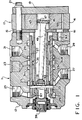
- FIG. 3 is an enlarged, fragmentary, axial cross-section, similar to FIG. 1, taken on line 3-3 of FIG. 2.
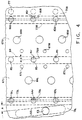
- FIG. 4 is an enlarged, fragmentary, overlay view, similar to FIG. 2, with the valving displaced to a first operating position (a left turn).
- FIG. 5 is an enlarged, fragmentary, axial cross-section, taken on line 5-5 of FIG. 2.
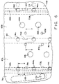
- FIG. 6 is an enlarged, fragmentary, overlay view, similar to FIG. 3, but with the valving displaced toward a maximum displacement position (still in a left turn).
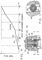
- FIG. 9 is a graph of orifice FLOW AREA versus VALVE DISPLACEMENT for the main variable flow control orifice, showing the rotary orifice (A1r, dashed line), the axial orifice (A1a, broken line), and the sum (A1 - TOTAL, solid line) of the two orifices.
- FIG. 10 is an enlarged, fragmentary, axial cross-section, similar to FIG. 3, but on a larger scale, illustrating an alternative embodiment of the present invention.
- FIG. 11 is an axial cross-section, taken on line 11-11 of FIG. 10, and on the same scale.
- the fluid controller may be of the type illustrated and described in U.S. Patent No. Re. 25,126, assigned to the assignee of the present invention.
- the subject embodiment is more specifically of the type illustrated and described in U.S. Patent No. 5,016,672, also assigned to the assignee of the present invention.
- the present invention differs very substantially from the above-cited patents, as will be described in greater detail subsequently, primarily in connection with the description of the controller valving in FIGS. 2 through 6.
- the fluid controller 11 comprises several sections, including a valve housing section 13, a wear plate 15, a section comprising a fluid meter 17, and an end cap 19. These sections are held together in tight sealing engagement by means of a plurality of bolts 21, which are in threaded engagement with the valve housing section 13.
- the valve housing section defines a fluid inlet port 23 (shown only in dotted lines in FIG. 1), a fluid return port 25, a pair of control (cylinder) fluid ports 27 and 29, and a load sensing fluid port 31.
- the valve housing section 13 also defines a valve bore 33, and rotatably disposed therein is the controller valving which comprises a primary, rotatable valve member 35 (also referred to hereinafter as the "spool"), and a cooperating, relatively rotatable follow-up valve member 37 (also referred to hereinafter as the "sleeve").
- the controller valving which comprises a primary, rotatable valve member 35 (also referred to hereinafter as the "spool"), and a cooperating, relatively rotatable follow-up valve member 37 (also referred to hereinafter as the "sleeve").
- a primary, rotatable valve member 35 also referred to hereinafter as the "spool”
- a cooperating, relatively rotatable follow-up valve member 37 also referred to hereinafter as the "sleeve”
- the spool 35 and the sleeve 37 will be described in greater detail subsequently.
- the fluid meter 17 may be of the type well known in the art, and in the subject embodiment, includes an internally-toothed ring member 41, and an externally-toothed star member 43.
- the star member 43 is eccentrically disposed within the ring member 41, for orbital and rotational movement relative thereto.
- the star member 43 defines a set of internal splines 45, and in splined engagement therewith is a set of external splines 47 formed at the rearward end of a main drive shaft 49, which has a bifurcated forward end 51.
- the forward end 51 permits driving connection between the shaft 49 and the sleeve 37, by means of a drive pin 53.
- the ends of the pin 53 pass through a pair of pin openings 55 (not shown in FIG. 1, but shown in FIG. 2) defined by the spool 35, and are received in relatively close fit openings in the sleeve 37.
- pressurized fluid flows through the various passages and ports defined by the spool 35 and sleeve 37, then flows through the fluid meter 17, causing orbital and rotational movement of the star 43, within the ring 41.
- Such movement of the star 43 causes rotational follow-up movement of the sleeve 37, by means of the drive shaft 49 and drive pin 51, to maintain a particular relative displacement between the spool 35 and sleeve 37.
- the particular relative displacement (referred to hereinafter as an "operating position"), is generally proportional to the rate of rotation of the steering wheel, i.e., the rate of rotation of the spool 35.
- a neutral centering spring arrangement disposed adjacent the forward end (left end in FIG. 1) of the spool 35 and the sleeve 37, is a neutral centering spring arrangement, represented in FIG. 1 by a portion of a coiled compression spring 57.
- the spring arrangement may be of the type illustrated and described in greater detail in co-pending application EP-A-0 542 285, published on 19.05.93, for a "FLUID CONTROLLER HAVING ROTARY/AXIAL VALVING, AND SPRING ARRANGEMENT THEREFOR", assigned to the assignee of the present invention.
- the spring arrangement would include one, two, or perhaps three of the coiled springs 57, the function of which is to bias the sleeve 37 toward a "neutral position" (as that term will be defined in connection with FIG. 2), relative to the spool 35.
- the spool 35 As the steering wheel is rotated, for example, in a counter-clockwise direction, to achieve a left turn of the vehicle, the spool 35 is also rotated counter-clockwise, as viewed by the vehicle operator, opening up a series of variable flow control orifices between the spool 35 and the sleeve 37. These orifices permit fluid communication from the annular chamber 23c through the valving, then through the radial bores 65R and the axial bores 63 to the expanding volume chambers 59 of the fluid meter 17.
- the above-described fluid path, or some portion thereof, is typically referred to as the "main fluid path", and the use of that term hereinafter and in the appended claims will be understood to mean the above-described fluid path, or a portion thereof, when the spool 35 and the sleeve 37 are in any type of operating position.
- variable flow control orifices in the controller valving, primarily in response to axial motion of the sleeve 37, relative to the spool 35 although, in the subject embodiment, there are also variable flow control orifices defined in response to rotary motion of the spool 35 relative to the sleeve 37.
- the sleeve in order to facilitate axial motion of the sleeve 37, relative to the spool 35, the sleeve is axially shorter than the adjacent portion of the spool.
- the spool 35 and sleeve 37 will be described in greater detail, with regard to the various ports and passages defined thereby.
- many of the ports and passages are arranged symmetrically, or generally symmetrically with respect to the annular chamber 23c, and such elements will be described by a reference numeral, followed by either an "L” or an "R”, to indicate that the element is located on either the left side or the right side, respectively, of the chamber 23c.
- certain of the other elements are either centered relative to the chamber 23c, or, although not centered, do not have a corresponding element oppositely disposed about the chamber 23c, and will be referred to by use of a reference numeral alone.
- FIGS. 2, 4, and 6 are intended to illustrate primarily the interface between the spool 35 (primarily, dashed lines) and the sleeve 37 (solid lines).
- the spool 35 defines a pair of generally annular meter grooves 67L and 67R, which cooperate to define therebetween a spool land 69. Disposed toward the left end in FIGS. 2 and 3, the spool 35 defines a generally annular tank groove 71L, and disposed toward the right end, the spool defines a generally annular tank groove 71R.
- the spool Disposed between the grooves 67L and 71L, the spool defines a spool land 73L, and similarly, the grooves 67R and 71R cooperate to define a spool land 73R.
- the spool land 69 is axially aligned with the annular chamber 23c, while the spool lands 73L and 73R are axially aligned with the annular chambers 27c and 29c, respectively.
- the portion of the spool 35 which forms the tank groove 71L also defines the pair of pin openings 55, mentioned previously in connection with FIG. 1.
- the construction and function of the openings 55 will be described in greater detail subsequently. It should be noted, however, that the openings extend from the groove 71L through to the interior of the spool 35.
- the spool land 69 defines a circumferentially-extending notch 75L, and a circumferentially-extending notch 75R, the notches 75L and 75R being in open communication with the meter grooves 67L and 67R, respectively.
- the spool 35 also defines a plurality of tank ports 77, disposed to the right of the spool land 73R, and extending through to the interior of the spool.
- the sleeve 37 defines a plurality of pressure ports 85. As may be seen only in FIG. 2, not all of the pressure ports 85 are the same size. Just above the line 5-5 in FIG. 2, the port 85 is somewhat smaller than the ports which are "above” it in FIG. 2, while the port 85 which is shown one-half at the bottom of FIG. 2 and one-half at the top of FIG. 2 is smaller still. Between the smaller ports just discussed, the spool 35 defines a load sense drain port 86 (which is shown solid in FIG. 2 for clarity, even though it is located in the spool), which will be discussed further in connection with FIG. 5.
- the "neutral" position of the spool 35 and sleeve 37 is illustrated, wherein the springs 57 bias the spool and sleeve to a position in which the ends of the drive pin 53 are disposed at the center (i.e., in a circumferential direction) of the pin openings 55.
- certain of the ports are in a neutral (i.e., in a circumferential direction) position relative to an adjacent notch.
- one of the ports 85 in FIG. 2 is disposed near the "upper" end of the notch 75R, such that relative rotation between the spool and the sleeve would be required for communication to occur from the port 85 to the notch 75R.
- a number of ports are in a neutral position (i.e., in an axial direction) relative to various spool passages.
- a neutral position i.e., in an axial direction
- flow through the ports 85 is blocked by the spool land 69, with each of the ports 85 being axially equidistant from the meter grooves 67L and 67R.
- flow through the operating ports 91L and 91R is blocked by the spool lands 73L and 73R, respectively, and each of the ports 91L and 91R is axially equidistant from the adjacent grooves 71L and 67L, and 67R and 71R, respectively.
- the metered fluid flows through the meter ports 89L, then through the meter groove 67L, then through the notch 79L and one of the operating ports 91L, the overlap therebetween defining a variable flow control orifice A4r.
- This metered fluid then flows through the annular chamber 27c (see FIG. 3) and then to the steering cylinder in the manner described previously.
- Return fluid from the steering cylinder flows through the annular chamber 29c, then through one of the operating ports 91R, which is in communication with the notch 81R, the overlap therebetween defining a variable flow control orifice A5r.
- Return fluid then flows through the tank groove 71R, then through the tank ports 77, through the interior of the spool 35, then out through the pin openings 55 and the drain holes 92 to the annular chamber 25c, then to the return port.
- fluid path just described with flow control orifices being defined in response to relative rotation of the spool and sleeve, comprises part of the main fluid path.
- formation of such rotary orifices is not an essential feature of the present invention, but instead, is included primarily to insure a fairly accurate, predictable beginning of steering flow, as the vehicle operator rotates the steering wheel.
- each of the ports defined by the sleeve may be considered as moving (i.e., relative to the spool) from its neutral position in FIG. 2 "downward” and slightly to the right along a path corresponding to the angle A.
- the notch 75R (and each of the other notches, as well) defines an angle B. If the angle B were equal to the angle A, continued relative movement of the port 85 and the notch 75R from the position shown in FIG. 4 would not result in any increase in the area of the A1r, A4r or A5r orifices.
- auxiliary ports 87L are beginning to communicate with the annular chamber 23c, thus receiving pressurized fluid from the inlet port 23.
- Pressurized fluid flows through the ports 87L, in parallel with the main fluid path and bypassing the fluid meter 17, then recombining with the main fluid path in the meter groove 67L, upstream of the A4r orifice.
- the result is a greater total flow to the steering cylinder than the capacity of the fluid meter 17, but with the flow to the steering cylinder still being in a predetermined relationship to the relative displacement between the spool and sleeve.
- the concept of a parallel amplification or bypass flow may be better understood by reference to U.S. Patent No. 4,759,182, issued in the name of Donald M. Haarstad for a "STEERING CONTROL UNIT WITH FLOW AMPLIFICATION", assigned to the assignee of the present invention.
- annular chambers 31cL and 31cR are connected by the passages 93L and 93R, respectively, to the load sensing port 31, only a single drain passage 95 is required to drain the entire load signal circuit, regardless of the direction, from the neutral position, in which the sleeve has been displaced.
- flow control orifices are defined in response to the relative axial position (and displacement) of the spool and sleeve.
- FIG. 7 in conjunction with FIG. 6, as the sleeve is displaced axially to the right, relative to the spool, from the position shown in FIG. 4 to the position shown in FIG. 6, formation of "axial" orifices begins. See also FIG. 9 wherein the transition from rotary orifices to axial orifices occurs between about 15 degrees and about 25 degrees of relative spool-sleeve displacement. Note in FIG.
- A1-TOTAL is drawn slightly above the individual A1 curves, for clarity, although over most of the displacement range, A1-TOTAL is merely equal to A1r or A1a.
- the ports 85 begin to communicate with the meter groove 67R, the cumulative overlap therebetween defining a main variable flow control orifice A1a. It will be understood by those skilled in the art that the main fluid path is the same as was described in connection with FIG. 4.
- the flow through the A1r, A4r, and A5r flow control orifices is substantially less than that through the A1a, A4a, and A5a flow control orifices.
- the area of overlap of each port and its respective groove in FIG. 6 is not especially large, it should be noted that "rotary" orifices have been defined by only a single port, and a single notch, whereas the axial orifices are defined by at least five ports (see FIG. 2) and their respective grooves, for either direction of displacement.
- the total flow area of the "axial" orifices is substantially greater than that of the "rotary" orifices.
- the layout view of FIG. 2 represents the entire 360° circumference of the spool and sleeve.
- the pin opening or slot 55 is configured such that displacement of the sleeve 37 from its neutral position to its maximum displacement position occurs in response to rotational movement of the spool 35, relative to the sleeve, of at least about 30°.
- An important feature and benefit of the present invention relates to pressure balancing.
- One of the problems typically experienced in a fluid controller of the type having a relatively displaceable spool and sleeve is that certain regions of the sleeve are subjected to relatively high pressure (e.g., 3000 psi), thus tending to "clamp" the sleeve about the spool. Such clamping is most likely to occur after a steering operation is complete, but there is a trapped load (and therefore, high pressure in the annular chamber 27c), the spool and sleeve return to neutral, and pressure within the spool and sleeve is relatively low.
- the pressure balancing groove 83L extends about the entire circumference of the spool land 73L.
- the pressure balancing groove 83R extends about the entire circumference of the spool land 73R.
- the auxiliary ports 87R continue to communicate a steering load pressure from the meter groove 67R, from downstream of the A1a orifice (instead of downstream of the A1r orifice), to the load sensing port 31 in the same manner as described previously.
- the auxiliary ports 87L continue to communicate an amplification flow from the annular chamber 23c into the meter groove 67L, upstream of the A4a orifice (instead of upstream of the A4r orifice) in the same manner as described previously.
- one of the ports 85 initially communicates with the notch 75L, to define therebetween the A1r flow control orifice.
- Pressurized fluid flows through the A1r orifice into the meter groove 67L, then through the meter ports 89L, through the fluid meter 17, then through the meter ports 89R and into the meter groove 67R.
- This metered fluid then flows through the notch 79R, and through one of the operating ports 91R, which defines the A4r flow control orifice, and from there to the steering cylinder.
- Exhaust fluid from the steering cylinder flows through one of the operating ports 91L, and through the notch 81L, which define the A5r orifice, and from there flows through the tank groove 71L and through the drain holes 92 to the return port 25.
- the ports 85 begin to communicate with the meter groove 67L to define the A1a flow control orifice
- the operating ports 91R begin to communicate with the meter groove 67R to define the A4a flow control orifice
- the operating ports 91L begin to communicate with the tank groove 71L to define the A5a flow control orifice.
- the auxiliary ports 87L now comprise load sensing ports, and communicate the steering load pressure from the meter groove 67L, downstream of the A1r and A1a orifices into the annular chamber 31cL, and from there through the passage 93L to the load sensing port 31.
- the auxiliary ports 87R are now in communication with the annular chamber 23c, to communicate amplification flow from the inlet port 23 through the ports 87R into the meter groove 67R in the manner described previously.
- FIGS. 10 and 11 there is illustrated an alternative embodiment of the present invention which relates, not to the valving configuration illustrated previously, but instead relates to the mechanism for displacing the sleeve 37 axially in response to relative rotation of the spool 35.
- the pin opening 55 acts somewhat in the manner of a cam surface, engaging the drive pin 53 with sufficient force to bias the sleeve 37 in one axial direction or the other.
- the pin opening 55 acts somewhat in the manner of a cam surface, engaging the drive pin 53 with sufficient force to bias the sleeve 37 in one axial direction or the other.
- the drive pin 53 is replaced with a modified drive pin 53' which, preferably, would be somewhat larger in diameter over most of its length, and would be received in a larger pin opening 55'.
- a cylindrical cap 107 is disposed about the portion 101, and insures proper location of the bearing set 103.
- the cap 107 is preferably just slightly smaller than the opening in the sleeve 37.
- the use of the ball bearing set 103 eliminates the rubbing engagement between the drive pin 53 and the pin opening 55, and instead, there is a rolling engagement between the outer race of the bearing set 103 and the pin opening 55'.
Landscapes
- Engineering & Computer Science (AREA)
- Chemical & Material Sciences (AREA)
- Combustion & Propulsion (AREA)
- Transportation (AREA)
- Mechanical Engineering (AREA)
- Power Steering Mechanism (AREA)
Claims (20)
- Régulateur (11) pouvant fonctionner pour contrôler le débit de fluide d'une source de fluide pressurisé vers un dispositif activé par pression de fluide; ledit régulateur étant du type comportant un moyen formant corps (13) définissant une lumière d'admission (23) destinée à être connectée à la source de fluide pressurisé, une lumière de retour (25) destinée à être connectée à un réservoir, et une première (27) et une deuxième (29) lumière de fluide de contrôle destinées à être connectées au dispositif activé par pression de fluide; un moyen formant soupape disposé dans ledit moyen formant corps et comprenant un élément soupape principal (35) pouvant tourner et un élément soupape secondaire (37) coopérant avec le précédent et pouvant tourner de manière relative à celui-ci, lesdits éléments soupapes principal et secondaire définissant une position neutre (figure 2) et une première position de fonctionnement dans laquelle ledit élément soupape principal est déplacé par rotation de ladite position neutre, par rapport audit élément soupape secondaire, dans une première direction; ledit élément soupape principal (35) définissant un premier (67R) et un deuxième (67L) passage de fluide, et ledit élément soupape secondaire (37) définissant une première (85) et une deuxième (91L) lumière de fluide en communication de fluide continue avec ladite lumière d'admission (23) et ladite première lumière de fluide de contrôle (27) respectivement; lesdites première et deuxième lumières de fluide étant privées de communication de fluide avec lesdits premier et deuxième passages de fluide, respectivement, quand lesdits éléments soupapes sont à ladite position neutre, et lesdites première et deuxième lumières de fluide étant en communication de fluide avec lesdits premier et deuxième passages de fluide, respectivement, quand lesdits éléments soupapes sont dans ladite première position de fonctionnement; ledit moyen formant corps (13) et lesdits éléments soupapes coopérant pour définir un premier circuit de fluide principal (23c, 85, 67R, 89R, 17, 89L, 91L, 27c, 29c, 91R, 71R, 77, 25c) établissant une communication de fluide de ladite lumière d'admission (23) vers ladite première lumière de fluide de contrôle (27) et de ladite deuxième lumière de fluide de contrôle (29) vers ladite lumière de retour (25), quand lesdits éléments soupapes sont dans ladite première position de fonctionnement; caractérisé par:(a) des moyens (53, 55) pouvant être actionnés, en réponse au déplacement rotatoire relatif desdits éléments soupapes principal et secondaire, de façon à déplacer l'élément soupape secondaire dans une première direction axiale vers ladite première position de fonctionnement;(b) lesdites première (85) et deuxième (91L) lumières de fluide coopérant respectivement avec lesdits premier (67R) et deuxième (67L) passages de fluide pour définir respectivement un premier (A1a) et un deuxième (A4a) orifice axial de régulation de débit à section variable quand ledit élément soupape secondaire est déplacé axialement vers ladite première position de fonctionnement; et(c) ledit premier circuit de fluide principal comportant lesdits premier (A1a) et deuxième (A4a) orifices axiaux de régulation de débit à section variable.
- Régulateur (11) selon la revendication 1, caractérisé en ce que le fluide circulant à travers lesdits premier (A1a) et deuxième (A4a) orifices axiaux de régulation de débit à section variable comprend une portion importante du débit de fluide traversant ledit premier circuit de fluide principal quand lesdits éléments soupapes sont dans ladite première position de fonctionnement.
- Régulateur (11) selon la revendication 1, caractérisé en ce que lesdits éléments soupapes principal (35) et secondaire (37) coopèrent pour définir une position de déplacement maximal et en ce que le débit de fluide traversant lesdits premier (A1a) et deuxième (A4a) orifices axiaux de régulation de débit à section variable comprend essentiellement tout le débit de fluide circulant traversant ledit premier circuit de fluide principal quand lesdits éléments soupapes sont dans ladite position de déplacement maximal.
- Régulateur (11) selon la revendication 1, caractérisé par des moyens à fluide (17) pour imprimer un mouvement solidaire audit élément soupape secondaire (37), proportionnel au volume de débit de fluide traversant ledit premier circuit de fluide principal quand lesdits éléments soupapes sont dans ladite première position de fonctionnement.
- Régulateur (11) selon la revendication 4, caractérisé en ce que lesdits moyens à fluide (17) comprennent un élément de mesure (43) pouvant tourner en réponse au débit de fluide traversant ledit premier circuit de fluide principal, et un élément arbre (49) pouvant tourner avec ledit élément de mesure et pouvant fonctionner de façon à imprimer ledit mouvement solidaire audit élément soupape secondaire (37).
- Régulateur (11) selon la revendication 5, caractérisé en ce que ledit élément arbre (49) comporte un élément d'entraînement (53) s'étendant radialement a travers au moins une ouverture d'entraînement (55) définie par ledit élément soupape principal (35) et en emboîtement dans ledit élément soupape secondaire (37), lesdits moyens (53, 55) destinés à imprimer un mouvement solidaire audit élément soupape secondaire comportant ledit élément d'entraînement et ledit emboîtement de celui-ci dans ledit élément soupape secondaire.
- Régulateur (11) selon la revendication 6, caractérisé en ce que ladite ouverture d'entraînement comprend une fente allongée (55) s'étendant à la fois circonférentiellement et axialement, par laquelle le mouvement rotatoire dudit élément soupape principal (35) par rapport audit élément soupape secondaire (37) déplace ledit élément soupape secondaire dans ladite première direction axiale.
- Régulateur (11) selon la revendication 7, caractérisé en ce que ladite extension axiale et circonférentielle de ladite fente allongée (55) est sélectionnée pour déplacer lesdits éléments soupapes de ladite position neutre vers une position de déplacement maximal en réponse audit mouvement rotatoire dudit élément soupape principal (35) par rapport audit élément soupape secondaire (37), ce mouvement étant égal à au moins trente degrés environ.
- Régulateur (11) selon la revendication 8, caractérisé en ce que le mouvement desdits éléments soupapes principal (35) et secondaire (37) de ladite position neutre vers ladite position de déplacement maximal se produit en réponse audit mouvement rotatoire de l'élément soupape principal par rapport audit élément soupape secondaire, ce mouvement étant égal à au moins quarante-cinq degrés environ.
- Régulateur (11) selon la revendication 1, caractérisé en ce que ledit moyen formant corps (13) définit une gorge de pression annulaire (23c) en communication de fluide continue avec ladite lumière d'admission (23), ladite première lumière de fluide (85) définie par l'élément soupape secondaire (37) étant disposée en communication de fluide continue avec ladite gorge de pression annulaire, lorsque ledit élément soupape secondaire se déplace axialement entre ladite position neutre et ladite position de déplacement maximal (figure 6).
- Régulateur (11) selon la revendication 10, caractérisé en ce que lesdits premier et deuxième passages de fluide définis par ledit élément soupape principal (35) comprennent une première (67R) et une deuxième (67L) gorges globalement annulaires, disposées axialement sur des côtés opposés de ladite gorge de pression annulaire (23c).
- Régulateur (11) selon la revendication 11, caractérisé en ce que ledit moyen formant corps (13) définit une lumière de détection de charge (31) et une gorge annulaire de détection de charge (31cR) disposée de façon adjacente à ladite gorge de pression annulaire (23c), ledit élément soupape secondaire (37) définissant une lumière de détection de charge (87R) établissant une communication de fluide continue entre ladite première gorge annulaire (67R) définie par ledit élément soupape principal (35) et ladite gorge annulaire de détection de charge (31cR) quand lesdits éléments soupapes sont dans ladite première position de fonctionnement.
- Régulateur (11) selon la revendication 12, caractérisé en ce qu'il comprend des moyens à fluide (17) pour imprimer un mouvement solidaire audit élément soupape secondaire (37) proportionnel au volume de débit de fluide traversant ledit premier circuit de fluide principal, et en ce que ledit élément soupape secondaire définit une lumière d'amplification de débit (87L) disposée de façon à établir une communication de fluide continue entre ladite gorge de pression annulaire (23c) et ladite deuxième gorge annulaire (67L) quand lesdits éléments soupapes sont dans ladite première position de fonctionnement.
- Régulateur (11) selon la revendication 1, caractérisé en ce que ledit élément soupape principal (35) définit une première saillie de piston-valve (73L) disposée axialement de façon adjacente audit deuxième passage de fluide (67L) et disposée de façon à bloquer la communication de fluide dudit deuxième passage de fluide vers ladite deuxième lumière de fluide (91L) définie par ledit élément soupape secondaire (37) quand lesdits éléments soupapes sont à ladite position neutre.
- Régulateur (11) selon la revendication 14, caractérisé en ce que ladite première saillie de piston-valve (73L) définit une première gorge annulaire d'équilibrage de pression (83L) disposée de façon à être en communication de fluide continue avec ladite deuxième lumière de fluide (91L) définie par ledit élément soupape secondaire (37), lorsque lesdits éléments soupapes sont déplacés de ladite position neutre vers ladite première position de fonctionnement.
- Régulateur (11) selon la revendication 15, caractérisé en ce que ledit élément soupape secondaire (37) définit une troisième lumière de fluide (91R) en communication de fluide continue avec ladite deuxième lumière de fluide de contrôle (29), ladite troisième lumière de fluide étant privée de communication de fluide avec ladite lumière de retour (25) quand lesdits éléments soupapes sont à ladite position neutre, et ladite troisième lumière de fluide étant en communication de fluide avec ladite lumière de retour quand lesdits éléments soupapes sont dans ladite première position de fonctionnement.
- Régulateur (11) selon la revendication 16, caractérisé en ce que ledit élément soupape principal (35) définit une deuxième saillie de piston-valve (73R) disposée axialement de façon adjacente audit premier passage de fluide (67R) et disposée de façon à bloquer toute communication de fluide dudit premier passage de fluide à travers ladite troisième lumière de fluide (91R) quand lesdits éléments soupapes sont à ladite position neutre, ladite deuxième saillie de piston-valve (73R) définissant une deuxième gorge annulaire d'équilibrage de pression (83R) disposée de façon à être en communication de fluide continue avec ladite troisième lumière de fluide définie par ledit élément soupape secondaire, lorsque lesdits éléments soupapes sont déplacés de ladite position neutre vers ladite première position de fonctionnement.
- Régulateur (11) selon la revendication 1, caractérisé en ce que ledit élément soupape principal (35) définit un passage de fluide rotatif s'étendant axialement (75R) en communication de fluide ouverte avec ledit premier passage de fluide (67R), ladite première lumière de fluide (85) étant privée de communication de fluide avec ledit passage de fluide rotatif quand lesdits éléments soupapes sont à ladite position neutre, ladite première lumière de fluide communiquant avec ledit passage de fluide rotatif pour définir un orifice rotatif de régulation de débit à section variable (A1r) lorsque ledit élément soupape principal est déplacé par rotation de ladite position neutre par rapport audit élément soupape secondaire, dans ladite première direction, le débit de fluide traversant ledit orifice rotatif de régulation de débit à section variable (A1r) comprenant une partie dudit premier circuit de fluide principal.
- Régulateur (11) selon la revendication 18, caractérisé en ce que ledit orifice rotatif de régulation de débit à section variable (A1r) commençant à s'ouvrir avant que ledit premier orifice axial de régulation de débit à section variable (A1a) ne commence à s'ouvrir lui-même, lorsque lesdits éléments soupapes sont déplacés de ladite position neutre vers ladite première position de fonctionnement.
- Régulateur (11) selon la revendication 18, caractérisé en ce que le débit de fluide traversant ledit orifice rotatif de régulation de débit à section variable (A1r) est sensiblement inférieur au débit de fluide traversant ledit premier orifice axial de régulation de débit à section variable (A1a), quand lesdits éléments soupapes sont dans ladite première position de fonctionnement.
Applications Claiming Priority (2)
| Application Number | Priority Date | Filing Date | Title |
|---|---|---|---|
| US07/819,715 US5186212A (en) | 1990-10-24 | 1992-01-13 | Fluid controller having axial modulation |
| US819715 | 1992-01-13 |
Publications (2)
| Publication Number | Publication Date |
|---|---|
| EP0551623A1 EP0551623A1 (fr) | 1993-07-21 |
| EP0551623B1 true EP0551623B1 (fr) | 1996-05-15 |
Family
ID=25228850
Family Applications (1)
| Application Number | Title | Priority Date | Filing Date |
|---|---|---|---|
| EP19920121336 Expired - Lifetime EP0551623B1 (fr) | 1992-01-13 | 1992-12-15 | Soupape hydraulique avec modulation axiale |
Country Status (5)
| Country | Link |
|---|---|
| US (1) | US5186212A (fr) |
| EP (1) | EP0551623B1 (fr) |
| JP (1) | JPH05246336A (fr) |
| DE (1) | DE69210791T2 (fr) |
| DK (1) | DK0551623T3 (fr) |
Families Citing this family (9)
| Publication number | Priority date | Publication date | Assignee | Title |
|---|---|---|---|---|
| DE19546282C2 (de) * | 1995-12-12 | 1997-09-25 | Danfoss As | Hydraulische Lenkeinrichtung und Verfahren zum Lenken eines Fahrzeugs |
| US7036309B1 (en) * | 2004-01-15 | 2006-05-02 | Sauer-Danfoss Inc. | Method of creating feedback control in a closed hydrostatic circuit and a control system therefore |
| US7862875B2 (en) * | 2004-10-04 | 2011-01-04 | Trico Corporation | Flinger disc |
| US7163421B1 (en) * | 2005-06-30 | 2007-01-16 | Amphenol Corporation | High speed high density electrical connector |
| US7213502B2 (en) * | 2005-09-09 | 2007-05-08 | Caterpillar Inc | Robustly stable servo-controlled metering poppet valve |
| US7283900B1 (en) | 2006-03-14 | 2007-10-16 | Deere & Company | Work vehicle steering system with flow-metering curve selection and associated method |
| US7913800B2 (en) * | 2006-10-30 | 2011-03-29 | Deere & Company | Steering system with variable flow rate amplification ratio and associated method |
| US8147684B2 (en) * | 2009-03-27 | 2012-04-03 | Trico Corporation | Apparatus and methods for lubricant filtration and drum pump filtration system |
| US8147683B2 (en) * | 2010-01-22 | 2012-04-03 | Trico Corporation | Portable lubricant filtration system and method |
Family Cites Families (7)
| Publication number | Priority date | Publication date | Assignee | Title |
|---|---|---|---|---|
| US2833253A (en) * | 1955-06-13 | 1958-05-06 | Deere Mfg Co | Power steering for vehicles |
| US3152610A (en) * | 1961-09-11 | 1964-10-13 | New York Air Brake Co | Hydraulic device |
| US3385057A (en) * | 1964-08-25 | 1968-05-28 | Trw Inc | Hydraulic controller |
| US3887028A (en) * | 1974-02-25 | 1975-06-03 | Trw Inc | Steering system |
| DE2712920C3 (de) * | 1977-03-24 | 1980-08-07 | Zahnradfabrik Friedrichshafen Ag, 7990 Friedrichshafen | Hydraulische Druckmittelsteuereinrichtung, insbesondere für hydrostatische Lenkeinrichtungen von Kraftfahrzeugen |
| US4759182A (en) * | 1987-07-24 | 1988-07-26 | Eaton Corporation | Steering control unit with flow amplification |
| US5016672A (en) * | 1990-04-23 | 1991-05-21 | Eaton Corporation | Steering controller with integral parallel control |
-
1992
- 1992-01-13 US US07/819,715 patent/US5186212A/en not_active Expired - Lifetime
- 1992-12-15 DK DK92121336T patent/DK0551623T3/da active
- 1992-12-15 EP EP19920121336 patent/EP0551623B1/fr not_active Expired - Lifetime
- 1992-12-15 DE DE69210791T patent/DE69210791T2/de not_active Expired - Fee Related
-
1993
- 1993-01-08 JP JP5018092A patent/JPH05246336A/ja active Pending
Also Published As
| Publication number | Publication date |
|---|---|
| DK0551623T3 (da) | 1996-06-03 |
| DE69210791D1 (de) | 1996-06-20 |
| US5186212A (en) | 1993-02-16 |
| JPH05246336A (ja) | 1993-09-24 |
| EP0551623A1 (fr) | 1993-07-21 |
| DE69210791T2 (de) | 1996-11-28 |
Similar Documents
| Publication | Publication Date | Title |
|---|---|---|
| EP0300269B1 (fr) | Unité de direction assistée à amplification de courant | |
| EP0388711B1 (fr) | Commande de direction à amplification du débit et à centre ouvert | |
| US4109679A (en) | Controller for fluid pressure operated devices | |
| US4781219A (en) | Fluid controller and dampening fluid path | |
| US5186212A (en) | Fluid controller having axial modulation | |
| EP0502456B1 (fr) | Dispositif de commande à fluide avec capacité de contrÔle de débit par priorité sensible à la charge | |
| US5620026A (en) | Fluid controller and improved backflow prevention therefor | |
| EP0362534B1 (fr) | Unité de direction assistée à amplification de courant et possibilité de direction manuelle | |
| EP0535556B1 (fr) | Dispositif de commande à fluide avec installation de clapet anti-retour améliorée | |
| US4558720A (en) | Closed-center controller for use with unequal area cylinder | |
| EP0775623B1 (fr) | Commande de direction à amplification du débit pour piston à surfaces inégales | |
| EP0567859B1 (fr) | Régulateur fluidique à fonctions supplémentaires variables | |
| EP0480431B1 (fr) | Dispositif de commande avec glissement réduit à déviation maximum | |
| EP0482440B1 (fr) | Vanne rotative de direction à angle de déflection large | |
| USRE34746E (en) | Open-center steering control unit with flow amplification | |
| EP0545113B1 (fr) | Soupape hydraulique à commande auxiliaire incorporée | |
| EP0453994B1 (fr) | Direction assistée à commande intégrale parallèle | |
| US6769451B2 (en) | Power beyond steering unit with bypass | |
| US5291963A (en) | Power steering system | |
| EP0264613B1 (fr) | Système de commande de fluide et trajet de fluide amorti | |
| EP1262393B1 (fr) | Système de direction à faible décalage de direction et son dispositif de commande à fluide amélioré | |
| US5161577A (en) | Fluid controller having rotary/axial valving, and spring arrangement therefor |
Legal Events
| Date | Code | Title | Description |
|---|---|---|---|
| PUAI | Public reference made under article 153(3) epc to a published international application that has entered the european phase |
Free format text: ORIGINAL CODE: 0009012 |
|
| AK | Designated contracting states |
Kind code of ref document: A1 Designated state(s): DE DK FR GB IT |
|
| 17P | Request for examination filed |
Effective date: 19931028 |
|
| 17Q | First examination report despatched |
Effective date: 19950721 |
|
| GRAH | Despatch of communication of intention to grant a patent |
Free format text: ORIGINAL CODE: EPIDOS IGRA |
|
| GRAA | (expected) grant |
Free format text: ORIGINAL CODE: 0009210 |
|
| AK | Designated contracting states |
Kind code of ref document: B1 Designated state(s): DE DK FR GB IT |
|
| REG | Reference to a national code |
Ref country code: DK Ref legal event code: T3 |
|
| REF | Corresponds to: |
Ref document number: 69210791 Country of ref document: DE Date of ref document: 19960620 |
|
| ITF | It: translation for a ep patent filed | ||
| ET | Fr: translation filed | ||
| PLBE | No opposition filed within time limit |
Free format text: ORIGINAL CODE: 0009261 |
|
| STAA | Information on the status of an ep patent application or granted ep patent |
Free format text: STATUS: NO OPPOSITION FILED WITHIN TIME LIMIT |
|
| 26N | No opposition filed | ||
| PGFP | Annual fee paid to national office [announced via postgrant information from national office to epo] |
Ref country code: DK Payment date: 20000919 Year of fee payment: 9 |
|
| PGFP | Annual fee paid to national office [announced via postgrant information from national office to epo] |
Ref country code: GB Payment date: 20001107 Year of fee payment: 9 |
|
| PGFP | Annual fee paid to national office [announced via postgrant information from national office to epo] |
Ref country code: FR Payment date: 20001204 Year of fee payment: 9 |
|
| PGFP | Annual fee paid to national office [announced via postgrant information from national office to epo] |
Ref country code: DE Payment date: 20001222 Year of fee payment: 9 |
|
| PG25 | Lapsed in a contracting state [announced via postgrant information from national office to epo] |
Ref country code: GB Free format text: LAPSE BECAUSE OF NON-PAYMENT OF DUE FEES Effective date: 20011215 Ref country code: DK Free format text: LAPSE BECAUSE OF NON-PAYMENT OF DUE FEES Effective date: 20011215 |
|
| REG | Reference to a national code |
Ref country code: GB Ref legal event code: IF02 |
|
| PG25 | Lapsed in a contracting state [announced via postgrant information from national office to epo] |
Ref country code: DE Free format text: LAPSE BECAUSE OF NON-PAYMENT OF DUE FEES Effective date: 20020702 |
|
| GBPC | Gb: european patent ceased through non-payment of renewal fee |
Effective date: 20011215 |
|
| PG25 | Lapsed in a contracting state [announced via postgrant information from national office to epo] |
Ref country code: FR Free format text: LAPSE BECAUSE OF NON-PAYMENT OF DUE FEES Effective date: 20020830 |
|
| REG | Reference to a national code |
Ref country code: DK Ref legal event code: EBP |
|
| REG | Reference to a national code |
Ref country code: FR Ref legal event code: ST |
|
| PG25 | Lapsed in a contracting state [announced via postgrant information from national office to epo] |
Ref country code: IT Free format text: LAPSE BECAUSE OF NON-PAYMENT OF DUE FEES;WARNING: LAPSES OF ITALIAN PATENTS WITH EFFECTIVE DATE BEFORE 2007 MAY HAVE OCCURRED AT ANY TIME BEFORE 2007. THE CORRECT EFFECTIVE DATE MAY BE DIFFERENT FROM THE ONE RECORDED. Effective date: 20051215 |