EP0551639A1 - Pied pour table de bureau, de laboratoire ou de travail - Google Patents
Pied pour table de bureau, de laboratoire ou de travail Download PDFInfo
- Publication number
- EP0551639A1 EP0551639A1 EP92121749A EP92121749A EP0551639A1 EP 0551639 A1 EP0551639 A1 EP 0551639A1 EP 92121749 A EP92121749 A EP 92121749A EP 92121749 A EP92121749 A EP 92121749A EP 0551639 A1 EP0551639 A1 EP 0551639A1
- Authority
- EP
- European Patent Office
- Prior art keywords
- frame part
- fixed frame
- base frame
- fixed
- frame according
- Prior art date
- Legal status (The legal status is an assumption and is not a legal conclusion. Google has not performed a legal analysis and makes no representation as to the accuracy of the status listed.)
- Ceased
Links
- 238000000034 method Methods 0.000 description 6
- 238000009420 retrofitting Methods 0.000 description 5
- 238000005553 drilling Methods 0.000 description 4
- 239000011152 fibreglass Substances 0.000 description 3
- 239000004033 plastic Substances 0.000 description 3
- 229920003023 plastic Polymers 0.000 description 3
- 230000001771 impaired effect Effects 0.000 description 2
- 239000000463 material Substances 0.000 description 2
- 239000012528 membrane Substances 0.000 description 2
- 230000015572 biosynthetic process Effects 0.000 description 1
- 238000011161 development Methods 0.000 description 1
- 230000018109 developmental process Effects 0.000 description 1
- 239000000428 dust Substances 0.000 description 1
- 230000000694 effects Effects 0.000 description 1
- 239000002184 metal Substances 0.000 description 1
- 230000002093 peripheral effect Effects 0.000 description 1
- 238000010079 rubber tapping Methods 0.000 description 1
- 210000002023 somite Anatomy 0.000 description 1
- 230000003068 static effect Effects 0.000 description 1
- 239000002699 waste material Substances 0.000 description 1
Images
Classifications
-
- A—HUMAN NECESSITIES
- A47—FURNITURE; DOMESTIC ARTICLES OR APPLIANCES; COFFEE MILLS; SPICE MILLS; SUCTION CLEANERS IN GENERAL
- A47B—TABLES; DESKS; OFFICE FURNITURE; CABINETS; DRAWERS; GENERAL DETAILS OF FURNITURE
- A47B21/00—Tables or desks for office equipment, e.g. typewriters, keyboards
- A47B21/06—Tables or desks for office equipment, e.g. typewriters, keyboards characterised by means for holding, fastening or concealing cables
-
- A—HUMAN NECESSITIES
- A47—FURNITURE; DOMESTIC ARTICLES OR APPLIANCES; COFFEE MILLS; SPICE MILLS; SUCTION CLEANERS IN GENERAL
- A47B—TABLES; DESKS; OFFICE FURNITURE; CABINETS; DRAWERS; GENERAL DETAILS OF FURNITURE
- A47B17/00—Writing-tables
- A47B17/02—Writing-tables with vertically-adjustable parts
-
- A—HUMAN NECESSITIES
- A47—FURNITURE; DOMESTIC ARTICLES OR APPLIANCES; COFFEE MILLS; SPICE MILLS; SUCTION CLEANERS IN GENERAL
- A47B—TABLES; DESKS; OFFICE FURNITURE; CABINETS; DRAWERS; GENERAL DETAILS OF FURNITURE
- A47B17/00—Writing-tables
- A47B17/03—Writing-tables with substantially horizontally extensible or adjustable parts other than drawers, e.g. leaves
- A47B17/033—Writing-tables with substantially horizontally extensible or adjustable parts other than drawers, e.g. leaves with parts added to the original furniture to enlarge its surface
-
- A—HUMAN NECESSITIES
- A47—FURNITURE; DOMESTIC ARTICLES OR APPLIANCES; COFFEE MILLS; SPICE MILLS; SUCTION CLEANERS IN GENERAL
- A47B—TABLES; DESKS; OFFICE FURNITURE; CABINETS; DRAWERS; GENERAL DETAILS OF FURNITURE
- A47B37/00—Tables adapted for other particular purposes
- A47B2037/005—Tables specially adapted for laboratories
-
- A—HUMAN NECESSITIES
- A47—FURNITURE; DOMESTIC ARTICLES OR APPLIANCES; COFFEE MILLS; SPICE MILLS; SUCTION CLEANERS IN GENERAL
- A47B—TABLES; DESKS; OFFICE FURNITURE; CABINETS; DRAWERS; GENERAL DETAILS OF FURNITURE
- A47B2200/00—General construction of tables or desks
- A47B2200/0035—Tables or desks with features relating to adjustability or folding
- A47B2200/005—Leg adjustment
- A47B2200/0051—Telescopic
- A47B2200/0052—Telescopic with two telescopic parts
- A47B2200/0053—Flat lifting device for desks with two telescopic sections
Definitions
- the invention relates to a base frame for a desk, laboratory or work table, in particular a height-adjustable table, according to the preamble of claim 1.
- Such a base frame is known from DE-GM 91 02 471.4.
- swivel arms of this type are also known for holding the telephone set or for accommodating storage compartments.
- a base frame for a desk, laboratory or work table with a fixed frame part on the bottom and a movable frame part which is adjustable therein in the vertical direction and which carries essentially horizontal support rails at its upper free end to support a table top, characterized in that on the fixed frame part in the exit plane of the movable frame part from the fixed frame part, attachment points can be retrofitted for at least one basic element fixed in the vertical direction.
- the at least one basic mounting element fixed in the vertical direction is attached to the fixed frame part in the exit plane of the movable frame part from the fixed frame part, the adjustment movement of the movable frame part in the fixed frame part is initially not hindered in any way, since in the area of the fixed frame part no holes or the like need to be retrofitted.
- the exit plane of the movable frame part from the fixed frame part lies essentially in the maximum vertical height extension of the fixed frame part, so that the entire vertical length extension of the fixed frame part is available.
- the base element which can be fixed in position on the fixed frame part can also extend essentially over the entire vertical height extent of the fixed frame part, so that the arrangement of further base elements on the base elements can take place in a variety of optimally adjustable altitudes.
- the attachment points are formed on both sides of the movable frame part on the fixed frame part.
- the distribution of forces is thereby largely symmetrical, so that the overall stability of the table on the one hand and the smooth movement of the table top height adjustment on the other hand are not impaired.
- the attachment points are formed by vertically extending bolts which engage in retaining tabs on the basic upgrade element.
- the engagement between the screw bolts and the retaining tabs is ensured by cap nuts covering the upper free end of the screw bolts. This forms a reliable connection between the attachment points on the fixed frame part and the at least one basic upgrade element.
- the bolts in this case can be inserted into receiving elements which are arranged in the fixed frame part, wherein according to claim 5 the receiving elements are plugs made of, for example, GRP, which are positively held in corresponding profile recesses in the fixed frame part, the attachment points for the at least one Attach the basic upgrade element to the fixed frame part without any complex drilling or other assembly work and therefore also easy to retrofit.
- the receiving elements are plugs made of, for example, GRP, which are positively held in corresponding profile recesses in the fixed frame part
- the basic upgrade element can be a hanging plate that runs vertically and thus essentially parallel to the fixed frame part.
- the basic upgrade element can be a plate-shaped, vertically extending component, bores can be easily formed on the plate, which then serve to fasten the actual upgrade elements.
- the smooth movement of the adjusting movement between the fixed and movable frame part is in no way influenced or even impaired.
- the hanging plate can be attached according to claim 8 on the outside and / or inside of the fixed frame part, so that the possible variations are further increased.
- the basic upgrade element can be a table top extending horizontally and perpendicularly to the fixed frame part. This results in an additional side table top running parallel to the already existing table top of the table, which can serve, for example, to accommodate a workplace printer, storage baskets or the like.
- the vertically extending hanging plate can be provided with perforations for receiving the actual upgrade elements.
- the perforation is carried out in a grid dimension.
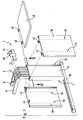
- a base frame 2 essentially comprises, according to FIG. 1, a base-side fixed frame part 4, as well as a movable frame part 6 guided or vertically movable or adjustable therein. At its upper free end, the movable frame part 6 carries essentially horizontally running support rails 8 for support a table top of the table, not shown in the drawing.
- the fixed frame part 4 is attached to a cross member 10 on the bottom.
- the attachment between the fixed frame part 4 and the cross member 10 on the bottom is advantageously adjustable, as is known from DE-GbM 91 09 212.4; To this extent reference is also made in full to this application.
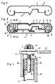
- the fixed frame part 4 and the movable frame part 6 are profiled in cross-section such that, according to FIG. 3, the movable frame part 6 is positively guided in the fixed frame part 4 by a sliding contact of several surface sections.
- the fixed frame part 4 is profiled in the region of its outside 12 such that after covering the outside 12 with a cover 14, two free spaces 16 and 18 remain, which serve as cable routing channels.
- the fixed frame part 4 is contoured semicircular in the region of its two vertically running narrow sides in accordance with an embodiment of the present invention.
- This semicircular contouring of the two vertical narrow sides of the fixed frame part 4 results in semicircular profile sections 20 and 22 in the cross section according to FIG. 2.
- these profile sections 20 and 22 serve to receive appropriately shaped plugs 24 and 26.
- the plugs 24 and 26 are thus also contoured semicircular in cross-section in the embodiment according to FIGS. 2 and 3, the dimensions of the profile sections 20 and 22 and the plugs 24 and 26 respectively are chosen so that the latter are held in the profile sections 20 and 22 slightly jamming.
- contouring of the profile sections 20 and 22 and thus that of the plugs 24 and 26 is not limited to the semicircular shape shown; deviating from this, e.g. B. semi-oval, triangular or polygonal profiles of the sections 20 and 22 and the plug 24 and 26 are equally possible.
- the plug 24 has a through hole 28 and the plug 26 has a through hole 30.
- the bores 28 and 30 run essentially vertically and thus essentially perpendicular to the cross member 10 of the fixed frame part 4.
- each of the plugs 24 and 26 and each of the bores 28 and 30 there for receiving a bolt 32 and 33.
- the diameters of the bolts 32 and 33 are selected so that they are slightly jammed circumferentially in the bore 28 and the bore 30 are held so that by applying a corresponding train or pressure to an upper free end 34 of the bolt 32 or 33, the latter is held displaceably in the respective bore 28 or 30.
- the material of the plugs 24 and 26 is chosen so that both the plugs 24 and 26 are secured in the profile sections 20 and 22, as well as the bolts 32 and 33 in the bores 28 and 30 in a concrete surface friction
- the plugs 24 and 26 are made of glass fiber reinforced plastic (GRP).
- GRP glass fiber reinforced plastic
- each bolt 32 (and 33) in the bores 28 and 30 is provided with a threaded portion 36 as shown in FIG. 4.
- the bolts 32 and 33 or the threaded sections 36 form attachment points at the free ends 34 of the bolts 32 and 33 for at least one basic upgrade element fixed in the vertical direction. Examples of such basic upgrade elements are illustrated in FIG. 1.
- an upgrade base element can be formed by a hanging plate 38 or 40, which has retaining tabs 42 or 44 at its upper end.
- the retaining tabs 42 and 44 are each provided with bores, the diameter of which is selected so that the free ends 34 of the bolts 32 and 33 provided with the threaded section 36 can pass through these bores and thus the retaining tabs 42 and 44, as in FIG. 4 shown.
- a table top 46 which also has holding tabs 48, which can engage with the upper free ends 34 of the bolts 32 and 33, as shown in FIG. 4. 4, a cap nut 50 can be screwed onto the upper free end 34 or the threaded section 36 there.
- the semicircular profile sections 20 and 22 in the fixed frame part 4 on both sides of the movable frame part 6 are usually closed by plastic cover caps. If the base frame 2 is to be retrofitted with one or more basic upgrade elements according to FIG. 1, these cover caps are first removed and the plugs 24 and 26 are subsequently pressed into the profile sections 20 and 22, until they are flush with the upper vertical plane of the fixed frame part 4, which is also the exit plane of the movable frame part 6 from the fixed frame part 4, as illustrated in FIG. 4.
- the bolts 32 and 33 are pressed into the bores 28 and 30 of the plugs 24 and 26 until only the threaded portion 36 at the free end 34 of the bolts 32 and 33 protrude from the exit plane of the movable frame part 6 from the fixed frame part 4.
- the plugs 24 and 26 are already arranged in the profile sections 20 and 22 at the factory.
- the visible or upper side of the plugs is closed in the area of the bores 28 and 30 with a relatively thin skin or membrane, so that the visible or upper sides of the plugs 24 and 26 are completely flat or even and an optically appealing closure of the profile sections 20 and 22 form in the exit plane of the movable frame part 6 from the fixed frame part 4.
- the skin or membrane is pierced when the bolts 32 and 33 are pressed into the bores 28 and 30 below.
- one or two hanging plates 38 or 40 and / or the table plate 46 are then attached to the fixed frame part 4 at the level of the exit plane. 4, for example, the retaining tabs 42 of the hanging plate 38 are inserted over the free ends 34 of the bolts 32 and 33 on both sides of the movable frame part 6. The bolts 32 and 33 thus hold the hanging plate 38 via the associated holding tabs 42 in a vertical position substantially parallel to the fixed frame part 4 or the cover 14 there.
- the upgrading or retrofitting of the base frame 2 is completed with the attachment of the hanging plate 38 , on the still protruding threaded portion 36 of the bolts 32 and 33, respectively a cap nut 50 is screwed on and subsequently the bolts 32 and 33 are pressed into the bores 28 and 30 of the plugs 24 and 26 by pressure from above until the undersides of the cap nuts 50 rest on the top of the retaining tabs 42 of the hanging plate 38.
- the hanging plate 40 with its holding tabs 42 is attached according to FIG Bolts 32 and 33 hung.
- the suspended hanging plates 38 and 40 are subsequently secured by screwing the cap nuts 50 onto the threaded sections 36 and subsequently the bolts 32 and 33 are pressed into the bores 28 and 30 again until the undersides of the cap nuts 50 are on the upper sides of the retaining tabs 44 of the hanging plate 40 sit on.
- a similar procedure is used if the two hanging plates 38 and 40 are to be fastened to the fixed frame part 4 together with the table plate 46 at the beginning of the retrofitting or retrofitting process, as can be seen from FIG. 4.
- the undersides of the cap nuts 50 are then seated on the upper sides of the retaining tabs 48 after the fastening process has been completed.
- the cap nuts 50 are loosened and, for example, the hanging plate 40 is unhooked after the holding tabs 48 of the table plate 46 have been lifted off.
- the table top 46 is then hung with its retaining tabs 48 over the bolts 32 and 33, the cap nuts 50 are screwed on and the bolts 32 and 33 are pressed deeper into the bores 28 and 30.
- the table tops 46 and 40 are already installed, the table top 46 should be retrofitted the frame part 4 are struck, the cap nuts 50 are loosened and the free ends 34 of the bolts 32 and 33 protruding from the upper side of the retaining lugs 44 are gripped with an appropriate tool, so that the bolts 32 and 33 by an amount at least corresponding to the thickness of the retaining lugs 48 can be drawn from the holes 28 and 30. Subsequently, the retaining tabs 48 are pushed over the free ends 34 of the bolts 32 and 33, which protrude further and are secured with the cap nuts 50.
- the hanging plates 38 and 40 are designed as basic upgrade elements, i. that is, the actual upgrade or retrofit elements are attached to the hanging plates 38 and 40.
- the hanging plates 38 and 40 have rows of holes 52, the spacings of the individual holes in the rows of holes 52 advantageously being present in a certain grid dimension. Supporting angles can then be screwed onto the holes in these rows of holes 52, in which the computing unit of a PC can be hung. Smaller hanging files, storage baskets, magazine compartments, test tube holders at laboratory tables and the like can be attached.
- pull-out rails can be screwed onto the mutually opposite inner hanging plates 40 of two such stands with a stand distance of, for example, 80 cm, to the rows of holes 52 of the two inner hanging plates 40, which then pull out a pull-out plate for receiving printers, paper storage compartments and the like carry more.
- the individual holes or bores of the rows of holes 52 are only predrilled from the rear of the hanging plates, so that the visible or outside of the hanging plates has no visible bores and is therefore visually appealing.
- these pre-drilled holes can then be completely pierced with self-tapping screws during the fastening process of the respective upgrade element on the hanging plate 38 or 40; a separate drilling process with the corresponding effort and chip waste is therefore not necessary.
- the table top 46 is particularly suitable for receiving workplace printers, storage baskets for printed paper, fax machines, modems, answering machines and the like.
- the adjustment movement of the movable frame part 6 within the fixed frame part 4 has no effect on the vertical positions of the basic upgrade elements 38, 40 and 46.
- the design of the basic upgrade elements 38 and 40 is not limited to the embodiment shown in the form of plates; it would also be conceivable, for example, to provide individual vertically running rails which each have a retaining tab 42 or 44 at their upper free end and which are individually hung on the bolts 32 and 33, the rails also, for example, two or three horizontally running stiffening elements have running between them, so that instead of the hanging plates 38 and 40 frame-like structures on one side or on both sides of the fixed frame part 4 are attached to the attachment points, the rows of holes 52 then being formed in the vertically extending frame parts.
- a further upgrade basic element 54 is provided according to FIG. 1, which can be fastened to the movable frame part 6 in the immediate vicinity of the carrier rails 8.
- This further basic upgrade element on the movable frame part 6 can be, for example, a receiving socket 56 for receiving the telescopic arm of a screen swivel arm, a telephone holder or a desk lamp as the actual upgrade element.
- the advantage of the arrangement of a further basic upgrade element on the movable frame part 6 is that when the base frame 2 is adjusted in height, that is to say during a relative movement between the fixed frame part 4 and the movable frame part 6, the further basic upgrade element 54 takes part in this height adjustment, so that after a Adjusting the height of the table top, the orientation of the computer screen, telephone holder, desk lamp or the like does not have to be changed.
- the individual basic upgrade elements 38, 40, 46 and 54 can be combined individually, in any combination with one another and completely independently of one another with the fixed frame part 4 or the movable frame part 6.
- the base frame 2 according to the invention can be adapted particularly variably and functionally to the respective working conditions.
- the bolts 32 can be removed from the bores 28 and 30 and the profile sections 20 and 22 with the plugs 24 and 26 located therein are closed by appropriately designed plastic caps which engage with their holding sections in the bores 28 and 30.
Landscapes
- Tables And Desks Characterized By Structural Shape (AREA)
Applications Claiming Priority (2)
| Application Number | Priority Date | Filing Date | Title |
|---|---|---|---|
| DE9200450U | 1992-01-16 | ||
| DE9200450U DE9200450U1 (de) | 1992-01-16 | 1992-01-16 | Fußgestell für einen Schreib-, Labor- oder Arbeitstisch |
Publications (1)
| Publication Number | Publication Date |
|---|---|
| EP0551639A1 true EP0551639A1 (fr) | 1993-07-21 |
Family
ID=6875076
Family Applications (1)
| Application Number | Title | Priority Date | Filing Date |
|---|---|---|---|
| EP92121749A Ceased EP0551639A1 (fr) | 1992-01-16 | 1992-12-21 | Pied pour table de bureau, de laboratoire ou de travail |
Country Status (2)
| Country | Link |
|---|---|
| EP (1) | EP0551639A1 (fr) |
| DE (1) | DE9200450U1 (fr) |
Cited By (3)
| Publication number | Priority date | Publication date | Assignee | Title |
|---|---|---|---|---|
| ES2066715A2 (es) * | 1993-03-01 | 1995-03-01 | Triana Valentin Palacio | Armazon para mesa de oficina o similar. |
| EP0645105A1 (fr) * | 1993-09-23 | 1995-03-29 | Eggersmann GmbH & Co. KG | Table et système à tables |
| EP0657123A1 (fr) * | 1993-12-06 | 1995-06-14 | Dewert Antriebs- und Systemtechnik GmbH & Co. KG | Elément de levage plat |
Families Citing this family (1)
| Publication number | Priority date | Publication date | Assignee | Title |
|---|---|---|---|---|
| US20190264153A1 (en) * | 2016-07-29 | 2019-08-29 | Juno Therapeutics, Inc. | Bioreactor console |
Citations (1)
| Publication number | Priority date | Publication date | Assignee | Title |
|---|---|---|---|---|
| FR2328423A1 (fr) * | 1975-10-22 | 1977-05-20 | Cobam | Meuble, tel que table ou bureau |
-
1992
- 1992-01-16 DE DE9200450U patent/DE9200450U1/de not_active Expired - Lifetime
- 1992-12-21 EP EP92121749A patent/EP0551639A1/fr not_active Ceased
Patent Citations (1)
| Publication number | Priority date | Publication date | Assignee | Title |
|---|---|---|---|---|
| FR2328423A1 (fr) * | 1975-10-22 | 1977-05-20 | Cobam | Meuble, tel que table ou bureau |
Cited By (3)
| Publication number | Priority date | Publication date | Assignee | Title |
|---|---|---|---|---|
| ES2066715A2 (es) * | 1993-03-01 | 1995-03-01 | Triana Valentin Palacio | Armazon para mesa de oficina o similar. |
| EP0645105A1 (fr) * | 1993-09-23 | 1995-03-29 | Eggersmann GmbH & Co. KG | Table et système à tables |
| EP0657123A1 (fr) * | 1993-12-06 | 1995-06-14 | Dewert Antriebs- und Systemtechnik GmbH & Co. KG | Elément de levage plat |
Also Published As
| Publication number | Publication date |
|---|---|
| DE9200450U1 (de) | 1992-03-26 |
Similar Documents
| Publication | Publication Date | Title |
|---|---|---|
| EP0362614A2 (fr) | Dispositif pour poste de travail pour bureau | |
| EP1971243A1 (fr) | Meuble avec conduite de câbles | |
| DE19815000A1 (de) | Verstellbare Regalanordnung für einen Computerarbeitsplatz | |
| DE4021248A1 (de) | Bausatz zur herstellung von buero-arbeitstischen | |
| DE3916095C2 (fr) | ||
| EP0332762A1 (fr) | Support d'appareil | |
| EP0551639A1 (fr) | Pied pour table de bureau, de laboratoire ou de travail | |
| CH680414A5 (en) | Office desk with different accessories - has rail at back above desk top for detachably installing fittings | |
| DE4437337C1 (de) | Tisch | |
| DE19836603C2 (de) | Höhenverstellbarer Arbeitstisch | |
| DE3814894C1 (fr) | ||
| EP0645281A1 (fr) | Pied de support d'un profilé de galerie de toit de véhicule | |
| EP2712516A2 (fr) | Système de levage pour un système de poste de travail réglable en hauteur et système de poste de travail doté d'un tel système de levage | |
| DE3111920A1 (de) | Arbeitstisch mit hoehenverstellbarer tischplatte | |
| DE2101297A1 (de) | Labortisch | |
| DE3730482C1 (en) | Desk with an additional stand-at desk board | |
| EP0068329B1 (fr) | Bureau | |
| DE3016353C2 (de) | Möbel mit verstellbarer Tischplatte | |
| DE10313029B3 (de) | Höhenverstellbare Duschkabine oder Duschwand | |
| DE10120106B4 (de) | Arbeitstisch | |
| DE29715923U1 (de) | Pultartiger Schreibtisch, insbesondere Lernschreibtisch | |
| DE2701273C3 (de) | Tisch mit einem unter dem Tischblatt verfahrbarem Schrank | |
| DE19912836A1 (de) | Arbeitstisch | |
| DE3837468C2 (fr) | ||
| DE102021129646A1 (de) | Vorrichtung zur Führung eines beweglichen Möbelteils relativ zu einem Möbelkorpus |
Legal Events
| Date | Code | Title | Description |
|---|---|---|---|
| PUAI | Public reference made under article 153(3) epc to a published international application that has entered the european phase |
Free format text: ORIGINAL CODE: 0009012 |
|
| AK | Designated contracting states |
Kind code of ref document: A1 Designated state(s): AT BE CH DE ES FR GB IT LI LU NL PT |
|
| 17P | Request for examination filed |
Effective date: 19940103 |
|
| 17Q | First examination report despatched |
Effective date: 19960108 |
|
| GRAG | Despatch of communication of intention to grant |
Free format text: ORIGINAL CODE: EPIDOS AGRA |
|
| STAA | Information on the status of an ep patent application or granted ep patent |
Free format text: STATUS: THE APPLICATION HAS BEEN REFUSED |
|
| 18R | Application refused |
Effective date: 19970619 |