EP0551924A2 - Mehrkanalgas-Analysierungsgerät und Verwendung - Google Patents
Mehrkanalgas-Analysierungsgerät und Verwendung Download PDFInfo
- Publication number
- EP0551924A2 EP0551924A2 EP19930101101 EP93101101A EP0551924A2 EP 0551924 A2 EP0551924 A2 EP 0551924A2 EP 19930101101 EP19930101101 EP 19930101101 EP 93101101 A EP93101101 A EP 93101101A EP 0551924 A2 EP0551924 A2 EP 0551924A2
- Authority
- EP
- European Patent Office
- Prior art keywords
- signal
- line
- input
- output
- gas
- Prior art date
- Legal status (The legal status is an assumption and is not a legal conclusion. Google has not performed a legal analysis and makes no representation as to the accuracy of the status listed.)
- Withdrawn
Links
- 238000000034 method Methods 0.000 title claims abstract description 39
- 230000000241 respiratory effect Effects 0.000 claims abstract description 51
- 239000000470 constituent Substances 0.000 claims abstract description 14
- 238000002372 labelling Methods 0.000 claims 3
- 239000007789 gas Substances 0.000 abstract description 342
- 230000003287 optical effect Effects 0.000 abstract description 181
- 230000037361 pathway Effects 0.000 abstract description 85
- 238000012545 processing Methods 0.000 abstract description 50
- 238000001514 detection method Methods 0.000 abstract description 45
- 230000000712 assembly Effects 0.000 abstract description 15
- 238000000429 assembly Methods 0.000 abstract description 15
- 238000007493 shaping process Methods 0.000 abstract description 7
- 230000035945 sensitivity Effects 0.000 abstract description 3
- 229910002092 carbon dioxide Inorganic materials 0.000 description 181
- GQPLMRYTRLFLPF-UHFFFAOYSA-N Nitrous Oxide Chemical compound [O-][N+]#N GQPLMRYTRLFLPF-UHFFFAOYSA-N 0.000 description 154
- 230000015654 memory Effects 0.000 description 45
- 239000000872 buffer Substances 0.000 description 32
- 230000014509 gene expression Effects 0.000 description 28
- 238000005259 measurement Methods 0.000 description 27
- 240000007320 Pinus strobus Species 0.000 description 24
- 238000012512 characterization method Methods 0.000 description 23
- 238000012546 transfer Methods 0.000 description 22
- 230000006854 communication Effects 0.000 description 21
- 238000004891 communication Methods 0.000 description 21
- 238000010586 diagram Methods 0.000 description 21
- 230000008569 process Effects 0.000 description 21
- 238000012937 correction Methods 0.000 description 20
- 230000006870 function Effects 0.000 description 17
- 229910052594 sapphire Inorganic materials 0.000 description 14
- 239000010980 sapphire Substances 0.000 description 14
- 239000012530 fluid Substances 0.000 description 10
- 101100521334 Mus musculus Prom1 gene Proteins 0.000 description 9
- 238000004364 calculation method Methods 0.000 description 9
- 210000002445 nipple Anatomy 0.000 description 9
- 230000004044 response Effects 0.000 description 8
- 230000008859 change Effects 0.000 description 7
- XLYOFNOQVPJJNP-UHFFFAOYSA-N water Substances O XLYOFNOQVPJJNP-UHFFFAOYSA-N 0.000 description 7
- 238000009530 blood pressure measurement Methods 0.000 description 6
- GGYFMLJDMAMTAB-UHFFFAOYSA-N selanylidenelead Chemical compound [Pb]=[Se] GGYFMLJDMAMTAB-UHFFFAOYSA-N 0.000 description 6
- 230000001360 synchronised effect Effects 0.000 description 6
- 230000007704 transition Effects 0.000 description 6
- 238000010521 absorption reaction Methods 0.000 description 5
- 230000005540 biological transmission Effects 0.000 description 5
- 210000003097 mucus Anatomy 0.000 description 5
- 101710129178 Outer plastidial membrane protein porin Proteins 0.000 description 4
- 102100037820 Voltage-dependent anion-selective channel protein 1 Human genes 0.000 description 4
- 239000011324 bead Substances 0.000 description 4
- 238000006243 chemical reaction Methods 0.000 description 4
- 210000004072 lung Anatomy 0.000 description 4
- 238000009423 ventilation Methods 0.000 description 4
- 241000894006 Bacteria Species 0.000 description 3
- 229920000557 Nafion® Polymers 0.000 description 3
- 241000700605 Viruses Species 0.000 description 3
- 230000001143 conditioned effect Effects 0.000 description 3
- 238000009826 distribution Methods 0.000 description 3
- 230000031700 light absorption Effects 0.000 description 3
- 239000000463 material Substances 0.000 description 3
- 230000029058 respiratory gaseous exchange Effects 0.000 description 3
- 230000002000 scavenging effect Effects 0.000 description 3
- 238000012360 testing method Methods 0.000 description 3
- 230000000007 visual effect Effects 0.000 description 3
- CURLTUGMZLYLDI-UHFFFAOYSA-N Carbon dioxide Chemical compound O=C=O CURLTUGMZLYLDI-UHFFFAOYSA-N 0.000 description 2
- 230000009471 action Effects 0.000 description 2
- 230000004913 activation Effects 0.000 description 2
- 238000004458 analytical method Methods 0.000 description 2
- 238000003491 array Methods 0.000 description 2
- 239000008280 blood Substances 0.000 description 2
- 210000004369 blood Anatomy 0.000 description 2
- 238000010276 construction Methods 0.000 description 2
- 230000002209 hydrophobic effect Effects 0.000 description 2
- 239000000203 mixture Substances 0.000 description 2
- 230000002093 peripheral effect Effects 0.000 description 2
- 230000000704 physical effect Effects 0.000 description 2
- 239000004810 polytetrafluoroethylene Substances 0.000 description 2
- 229920001343 polytetrafluoroethylene Polymers 0.000 description 2
- 239000011148 porous material Substances 0.000 description 2
- 238000005070 sampling Methods 0.000 description 2
- 125000006850 spacer group Chemical group 0.000 description 2
- MFRCZYUUKMFJQJ-UHFFFAOYSA-N 1,4-dioxane-2,5-dione;1,3-dioxan-2-one Chemical compound O=C1OCCCO1.O=C1COC(=O)CO1 MFRCZYUUKMFJQJ-UHFFFAOYSA-N 0.000 description 1
- 102100033044 Glutathione peroxidase 2 Human genes 0.000 description 1
- 102100033053 Glutathione peroxidase 3 Human genes 0.000 description 1
- 101000871129 Homo sapiens Glutathione peroxidase 2 Proteins 0.000 description 1
- 101000871067 Homo sapiens Glutathione peroxidase 3 Proteins 0.000 description 1
- 238000004566 IR spectroscopy Methods 0.000 description 1
- 235000011449 Rosa Nutrition 0.000 description 1
- XUIMIQQOPSSXEZ-UHFFFAOYSA-N Silicon Chemical compound [Si] XUIMIQQOPSSXEZ-UHFFFAOYSA-N 0.000 description 1
- VSYMNDBTCKIDLT-UHFFFAOYSA-N [2-(carbamoyloxymethyl)-2-ethylbutyl] carbamate Chemical compound NC(=O)OCC(CC)(CC)COC(N)=O VSYMNDBTCKIDLT-UHFFFAOYSA-N 0.000 description 1
- 230000002159 abnormal effect Effects 0.000 description 1
- 238000009825 accumulation Methods 0.000 description 1
- 230000001154 acute effect Effects 0.000 description 1
- 238000013459 approach Methods 0.000 description 1
- QVGXLLKOCUKJST-UHFFFAOYSA-N atomic oxygen Chemical compound [O] QVGXLLKOCUKJST-UHFFFAOYSA-N 0.000 description 1
- 230000008901 benefit Effects 0.000 description 1
- 230000007175 bidirectional communication Effects 0.000 description 1
- 230000017531 blood circulation Effects 0.000 description 1
- 238000009529 body temperature measurement Methods 0.000 description 1
- 230000003139 buffering effect Effects 0.000 description 1
- 239000001569 carbon dioxide Substances 0.000 description 1
- 238000004140 cleaning Methods 0.000 description 1
- 239000011248 coating agent Substances 0.000 description 1
- 238000000576 coating method Methods 0.000 description 1
- 230000000295 complement effect Effects 0.000 description 1
- 238000011109 contamination Methods 0.000 description 1
- 238000001816 cooling Methods 0.000 description 1
- 229920001577 copolymer Polymers 0.000 description 1
- 230000008878 coupling Effects 0.000 description 1
- 238000010168 coupling process Methods 0.000 description 1
- 238000005859 coupling reaction Methods 0.000 description 1
- 230000003111 delayed effect Effects 0.000 description 1
- 230000000694 effects Effects 0.000 description 1
- 238000001914 filtration Methods 0.000 description 1
- 239000003193 general anesthetic agent Substances 0.000 description 1
- 230000001771 impaired effect Effects 0.000 description 1
- 238000002955 isolation Methods 0.000 description 1
- 238000005304 joining Methods 0.000 description 1
- 239000007788 liquid Substances 0.000 description 1
- 238000012423 maintenance Methods 0.000 description 1
- 238000004519 manufacturing process Methods 0.000 description 1
- 238000012986 modification Methods 0.000 description 1
- 230000004048 modification Effects 0.000 description 1
- 239000001272 nitrous oxide Substances 0.000 description 1
- 230000005693 optoelectronics Effects 0.000 description 1
- 239000001301 oxygen Substances 0.000 description 1
- 229910052760 oxygen Inorganic materials 0.000 description 1
- 238000005201 scrubbing Methods 0.000 description 1
- 229910052710 silicon Inorganic materials 0.000 description 1
- 239000010703 silicon Substances 0.000 description 1
- 238000001356 surgical procedure Methods 0.000 description 1
- 239000000725 suspension Substances 0.000 description 1
- 230000001131 transforming effect Effects 0.000 description 1
Images











Classifications
-
- A—HUMAN NECESSITIES
- A61—MEDICAL OR VETERINARY SCIENCE; HYGIENE
- A61B—DIAGNOSIS; SURGERY; IDENTIFICATION
- A61B5/00—Measuring for diagnostic purposes; Identification of persons
- A61B5/08—Measuring devices for evaluating the respiratory organs
- A61B5/083—Measuring rate of metabolism by using breath test, e.g. measuring rate of oxygen consumption
-
- G—PHYSICS
- G01—MEASURING; TESTING
- G01N—INVESTIGATING OR ANALYSING MATERIALS BY DETERMINING THEIR CHEMICAL OR PHYSICAL PROPERTIES
- G01N21/00—Investigating or analysing materials by the use of optical means, i.e. using sub-millimetre waves, infrared, visible or ultraviolet light
- G01N21/17—Systems in which incident light is modified in accordance with the properties of the material investigated
- G01N21/25—Colour; Spectral properties, i.e. comparison of effect of material on the light at two or more different wavelengths or wavelength bands
- G01N21/31—Investigating relative effect of material at wavelengths characteristic of specific elements or molecules, e.g. atomic absorption spectrometry
- G01N21/35—Investigating relative effect of material at wavelengths characteristic of specific elements or molecules, e.g. atomic absorption spectrometry using infrared light
- G01N21/3504—Investigating relative effect of material at wavelengths characteristic of specific elements or molecules, e.g. atomic absorption spectrometry using infrared light for analysing gases, e.g. multi-gas analysis
-
- G—PHYSICS
- G01—MEASURING; TESTING
- G01N—INVESTIGATING OR ANALYSING MATERIALS BY DETERMINING THEIR CHEMICAL OR PHYSICAL PROPERTIES
- G01N21/00—Investigating or analysing materials by the use of optical means, i.e. using sub-millimetre waves, infrared, visible or ultraviolet light
- G01N21/17—Systems in which incident light is modified in accordance with the properties of the material investigated
- G01N21/25—Colour; Spectral properties, i.e. comparison of effect of material on the light at two or more different wavelengths or wavelength bands
- G01N21/31—Investigating relative effect of material at wavelengths characteristic of specific elements or molecules, e.g. atomic absorption spectrometry
- G01N2021/3129—Determining multicomponents by multiwavelength light
-
- G—PHYSICS
- G01—MEASURING; TESTING
- G01N—INVESTIGATING OR ANALYSING MATERIALS BY DETERMINING THEIR CHEMICAL OR PHYSICAL PROPERTIES
- G01N21/00—Investigating or analysing materials by the use of optical means, i.e. using sub-millimetre waves, infrared, visible or ultraviolet light
- G01N21/17—Systems in which incident light is modified in accordance with the properties of the material investigated
- G01N21/59—Transmissivity
- G01N21/61—Non-dispersive gas analysers
-
- G—PHYSICS
- G01—MEASURING; TESTING
- G01N—INVESTIGATING OR ANALYSING MATERIALS BY DETERMINING THEIR CHEMICAL OR PHYSICAL PROPERTIES
- G01N2201/00—Features of devices classified in G01N21/00
- G01N2201/12—Circuits of general importance; Signal processing
- G01N2201/121—Correction signals
Definitions
- Mass spectrometers are used for measuring the partial pressure of respiratory gases in, for example, operating room suites in which one spectrometer is shared by many rooms. Mass spectrometers have the advantage of measuring a multiplicity of gases; however, the disadvantages are their cost, maintenance and calibration requirements, slow response time, and noncontinuous measurement.
- Prior art non-dispersive infrared gas analyzers include features for making C0 2 and N 2 0 cross channel detection, temperature, and collision broadening corrections to their partial gas pressure measurements. Some of these corrections are made automatically by the analyzers while others are made manually by the operator.
- Non-dispersive infrared gas analyzers generally have two configurations. The first, and most common, is the sampling or side-stream type. This type diverts a portion of the patient's respiratory gas flow through a sample tube to the infrared analyzer.
- FIG. 1 is a schematic diagram of the multichannel gas analyzer system of the present invention.
- the system comprises patient airway adapter 106, analog section 102, and display section 104.
- Analog section 102 detects and measures certain constituent gases in a respiratory gas stream. This section also detects and measures other physical properties which affect the determination of the partial pressures of constituent gases, e.g., C0 2 , and N 2 0. The measured values for C0 2 , N 2 0, and the other physical properties are combined to calculate the "real" partial pressure of C0 2 and N 2 0. The "real" partial pressures of these gases are corrected for barometric pressure, optical bench pressure, temperature, collision broadening, cross-correction, and characterization of the detection circuitry and other detection components.
- Annular ledge 228 is fixed to the walls of opening 230 at the end nearest the valve.
- Hydrophobic filter 232 is disposed across opening 230 on the side of ledge 228 closest airway adapter section 238. Hydrophobic filter 232 can be fixed to annular ledge 228.
- annular ledge is not included and the filter is fixed to ledge 229. When annular ledge 228 is included, it seals the filter in place and prevents valve member 226 from contacting filter 232 when it is open and portions thereof move toward the filter.
- the airway adapter has been described as involving the joining two separate sections, specifically, sections 210 and 238. However, it is understood that the airway adapter can be of unitary construction.
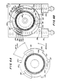
- the series of closely spaced openings indicated generally at 276 are for shielding the timing track optical path against ingress of background light.
- the single opening 277 is for shielding the position track optical path against the ingress of background light.
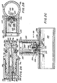
- block 294 has opening 301 into which sapphire window 297 is fixed.
- sapphire window 344 is fixed in an opening on the other side of block 294. These sapphire windows form opposing walls of N 2 0 reference cell 300 and gas pathway 298.
- In-line filter 312 is preferably constructed of expanded PTFE with a I micron pore size. The filter prevents foreign material from entering the gas pathway.
- ZERO + line 378 and ZERO- line 380 power zero valve 376.
- the voltage across these lines determines whether the zero value is configured to provide scrubbed room air from patient module zero gas pathway 404 or the respiratory gas stream from sample tube 174. Accordingly, the proper voltage is placed across ZERO + line 378 and ZERO- line 380 to cause zero valve to close off gas flow from sample tube 174 and open to the air flow in patient module zero gas pathway 404.
- sample pump is powered to draw 50 cc/min. of scrubbed room air through the pneumatic system.
- backflush pump 394 must be activated.
- the backflush pump 394 is activated by the voltage across BACKFLUSH PUMP line 396 and BACKFLUSH PUMP-line 398.
- backflush pump 394 is properly powered, room air is drawn through filter 402 and enters pump module backflush pathway 392. The room air next passes through pump 394. After passing through the backflush pump, the room air goes through remainder of pump module backflush pathway 392 and connector 390, and enters patient module backflush pathway 388. Once the room air has passed through backflush valve 382, it then enters the backflush tube 172 enroute airway adapter 106. The filtered room air enters airway adapter 106 and clears the filter.
- Figure 4B shows the powering circuits for backflush pump 394, diagnostic valve 412, external valve 1, 424, and external valve 2, 436.
- the circuit for powering sample pump 358 is in the analog processing circuitry and will be discussed subsequently.
- the D0-D3 signals of the optical bench data bus output from line driver 560 are input to quad. flip flop 606.
- This flip flop is clocked by the output of decoder 598 on line 602.
- quad. flip flop 606 provides a parallel 3-bit signal on lines 608, 610, and 612 which is input to the control inputs to multiplexer 558.
- a multiplexed signal is output from multiplexer 558 on line 559.
- the multiplexed signal on line 559 is processed by buffer amplifier 616 and output therefrom as the AMUX OUTPUT signal on 618.
- the AMUX OUTPUT signal is then sent to the analog input circuitry for further processing.
- Also output from multiplexer 558 and sent to the analog input circuitry is the AMUX RTN signal on line 620. This signal is tied to ground.
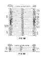
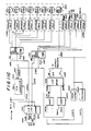
- octal flip flop 658 when octal flip flop 658 is clocked by the processed TIMING TRACK signal, its outputs are the GAS GATING signal on line 684, whose representative waveform is shown at 500 in Figure 6C; the REF GATING signal on line 686, whose representative waveform is shown at 488 in Figure 6C; and the DEMOD SYNC signal on line 688, whose representative waveform is shown at 476 in Figure 6C.
- the offset signal for each of the four gas or reference channels is generated by opening switches 740 or 752 at the appropriate time ( Figure 7B).
- the voltage output by D/A coverter 879 when these switches are open is that gas or reference channel's voltage offset. This channel offset is subtracted from the measured value for each gas.
- the output of the sample and hold circuit is input to comparator 866.
- the second input to comparator 866 is the VDAC signal on line 856.
- the output of comparator 866 is input to successive approximation register 870.
- the START SAR bar signal on line 886 is input to successive approximation register 870 to start the analog to digital conversion process.
- the SELSAR signal 884 is input to the output enable input of successive approximation register 870. The logic value of this signal controls placement of the converted data on data bus 880.
- the SARCLK ENB signal output from interface 876 on line 888 is for generating the SARCLK signal on line 890 as will be discussed in connection with Figure 8B.
- This is the first input to NAND gate 1110 for this purpose.
- the other input to that gate is the CLK 400 signal output from microprocessor 960 on line 970.
- the states of these signals control the output of NAND gate 1110.
- the output of NAND gate 1110 after inversion, the SARCLK signal, is used to turn the internal successive approximation register clock on and off.
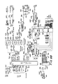
- the TIMING TRACK signal on line 538 output from the detector circuitry is input to frequency to voltage converter 944.
- the frequency to voltage converter output voltage, V OBSPEED is input to the analog processing circuitry and to error amplifier 945.
- the V OBSPEED signal is a voltage signal proportional to the chopper motor speed.
- Microprocessor 960 is a model 80186 CPU, commercially available from Intel Corp., Santa Clara, California.
- the parallel 8-bit signal, AD0-7, output from microprocessor 960 on line 994, is input to latch 1018.
- the AD0-7 signal may contain address or data information. When it contains address information and the values are input to latch 1018, when that latch is clocked, the latched values are placed on address bus 1022.
- the UART CLK signal on line 968 is input to controller 1059 and along with TxDB signal on line 1066 and the RxDB signal on line 1068 are for communications with external module 430 ( Figure 4A).
- the AIR PUMP SPEED signal on line 938 from analog switch 926 (Figure 7D) is input to the base of transistor 1114. This signal controls the SAMPLE PUMP voltage on line 1122.
- the SAMPLE PUMP- signal on line 1124 is tied to ground. The power delivered by the circuit is limited by fuse 1116 in line 1122 and by zener diodes 1118 and 1120. The voltage across these lines controls the speed of sample pump 358. ( Figure 4A).
- collision broading is determined by the following expression:
- the RESET OUT signal on line 1704 When microprocessor 1702 is powered on, the RESET OUT signal on line 1704 is asserted. The RESET OUT signal on line 1704 is input to inverter 1707. The output of the inverter is the RESET bar signal on line 1705. This signal is input to the RESET bar input of controller 1776.
- the BHE bar (bus high enable) signal on line 1724 also assists in enabling RAM 1768 when the high order bits D8-15 are written onto or read.
- CRT memory gate array 2102 and scroll/pixel gate array 2190 are the parallel 8 bit horizontal address bus HA0-7 on line 2182; the parallel 8 bit vertical address bus VA0-7 on line 2180; and the parallel 8 bit horizontal graphic address bus HGA0-7 on line 2184.
- the function of these address busses are known by one skilled in the art without further explanation.
- the WR bar and ANALOG SEL signals enable the decoder.
- the address bits A4-6 select the output of the decoder.
- the SCROLL SEL signal on line 1420 and the WR bar signal on line 1404 are the enabling inputs to decoder 2590.
- Address bits AI-3 input on line 1412 control the output from decoder 2590.
- NAND gate 2660 The first input to NAND gate 2660 is the output of the OR gate 2556. The inputs to this gate are the outputs of 8-bit magnitude comparator 2552.
- flip flop 2676 When flip flop 2676 is clocked, its Q bar output is input to AND gate 2686. This signal also enables 4- bit counter 2692 and is input to the selection input of multiplexer 2694.
- the output of 8-bit magnitude comparator 2572 is input to inverter 2580.
- the inverter's output is input to NAND gate 2582.
- the second input to this gate is the WNDEF bar signal on line 2581.
- the WNDEF bar signal determines if the current window available for scrolling is scrolled or not.
- the 4 bit counter 2702 is clocked by the PIX CLK signal on line 1906. This signal is inverted by inverter 2659. As such, counter 2702 is clocked one half clock pulse after other components clocked by the PIX CLK signal.
- the signal enabling bus buffer 3045 is the output of NAND gate 3032.
- the inputs to NAND gate 3032 are the WR bar signal on line 1404, the PROCRDWR bar signal on line 1946 and the GRPHL signal on line 1802.
- the master Control Server section is display Control Server section 3566.
- Analog Control Server section 3522 is slaved to master Control Server section 3566.
- the Control Servers control overall system operations.
- the display Control Server section 3566 monitors the buttons, knobs and switches of the control panel and appropriately adjust system operations based on their positions. Both the analog and display Control Servers provide data to their respective Scheduler section, 3506 or 3562, on "WHAT TO RUN".
- Display Measurement Tasks (DMT) section 3560 carries out data distribution to Trend Server section 3584, Alarm Server section 3588, Display Server section 3592, Digital Output Server section 3596, and Analog Output Server section 3600.
- DMT Display Measurement Tasks
- Digital Output Server section 3596 processes the data from DMT section 3560 and DDDB section 3561 for digital output to external devices.
- the AMT can have other programming which can be commanded to run other types of measurement calculations, e.g., Sa0 2 measurement tasks (oxygen saturation).
- the scrolling waveform at 3620 is not a display of gas detection information.
Landscapes
- Health & Medical Sciences (AREA)
- Life Sciences & Earth Sciences (AREA)
- Physics & Mathematics (AREA)
- Spectroscopy & Molecular Physics (AREA)
- General Health & Medical Sciences (AREA)
- Pathology (AREA)
- Surgery (AREA)
- Emergency Medicine (AREA)
- Pulmonology (AREA)
- Engineering & Computer Science (AREA)
- Biomedical Technology (AREA)
- Heart & Thoracic Surgery (AREA)
- Medical Informatics (AREA)
- Molecular Biology (AREA)
- Physiology (AREA)
- Animal Behavior & Ethology (AREA)
- Obesity (AREA)
- Public Health (AREA)
- Veterinary Medicine (AREA)
- Biophysics (AREA)
- Chemical & Material Sciences (AREA)
- Analytical Chemistry (AREA)
- Biochemistry (AREA)
- General Physics & Mathematics (AREA)
- Immunology (AREA)
- Investigating Or Analysing Materials By Optical Means (AREA)
- Other Investigation Or Analysis Of Materials By Electrical Means (AREA)
- Sampling And Sample Adjustment (AREA)
- Measurement Of The Respiration, Hearing Ability, Form, And Blood Characteristics Of Living Organisms (AREA)
- Saccharide Compounds (AREA)
- Medicines Containing Antibodies Or Antigens For Use As Internal Diagnostic Agents (AREA)
Applications Claiming Priority (4)
| Application Number | Priority Date | Filing Date | Title |
|---|---|---|---|
| US922043 | 1986-10-17 | ||
| US06/922,043 US4817013A (en) | 1986-10-17 | 1986-10-17 | Multichannel gas analyzer and method of use |
| US07/101,931 US4907166A (en) | 1986-10-17 | 1987-09-25 | Multichannel gas analyzer and method of use |
| US101931 | 1987-09-25 |
Related Parent Applications (1)
| Application Number | Title | Priority Date | Filing Date |
|---|---|---|---|
| EP87907697.4 Division | 1987-10-16 |
Publications (2)
| Publication Number | Publication Date |
|---|---|
| EP0551924A2 true EP0551924A2 (de) | 1993-07-21 |
| EP0551924A3 EP0551924A3 (en) | 1994-07-13 |
Family
ID=26798803
Family Applications (3)
| Application Number | Title | Priority Date | Filing Date |
|---|---|---|---|
| EP87907697A Expired - Lifetime EP0289581B1 (de) | 1986-10-17 | 1987-10-16 | Mehrkanalgas-analysierungsgerät und verwendung |
| EP93101050A Expired - Lifetime EP0551142B1 (de) | 1986-10-17 | 1987-10-16 | Mehrkanalgas-Analysierungsgerät |
| EP19930101101 Withdrawn EP0551924A3 (en) | 1986-10-17 | 1987-10-16 | Improved multichannel gas analyzer and method of use |
Family Applications Before (2)
| Application Number | Title | Priority Date | Filing Date |
|---|---|---|---|
| EP87907697A Expired - Lifetime EP0289581B1 (de) | 1986-10-17 | 1987-10-16 | Mehrkanalgas-analysierungsgerät und verwendung |
| EP93101050A Expired - Lifetime EP0551142B1 (de) | 1986-10-17 | 1987-10-16 | Mehrkanalgas-Analysierungsgerät |
Country Status (9)
| Country | Link |
|---|---|
| US (1) | US4907166A (de) |
| EP (3) | EP0289581B1 (de) |
| JP (1) | JPH0713591B2 (de) |
| AT (2) | ATE122807T1 (de) |
| CA (1) | CA1316703C (de) |
| DE (2) | DE3751308T2 (de) |
| DK (1) | DK330388A (de) |
| FI (1) | FI882886A7 (de) |
| WO (1) | WO1988002890A1 (de) |
Cited By (3)
| Publication number | Priority date | Publication date | Assignee | Title |
|---|---|---|---|---|
| EP1923668A1 (de) * | 2006-11-16 | 2008-05-21 | Tyco Electronics Raychem GmbH | Verfahren zur Verarbeitung eines analogen Sensorsignals in einer Gassensorenanordnung und Gerät zur Messwerteverarbeitung |
| EP1936357A1 (de) * | 2006-12-18 | 2008-06-25 | Tyco Electronics Raychem GmbH | Verfahren zur Verarbeitung eines analogen Sensorsignals in einer Gassensorenanordnung und Gerät zur Messwerteverarbeitung |
| EP2629082A3 (de) * | 2012-02-17 | 2013-09-25 | Contros Systems & Solutions GmbH | Vorrichtung zur Detektion eines Partialdrucks und Verfahren zum Betreiben derselben |
Families Citing this family (40)
| Publication number | Priority date | Publication date | Assignee | Title |
|---|---|---|---|---|
| US5415165A (en) * | 1986-02-27 | 1995-05-16 | Mountpelier Investments | Tonometric catheter combination |
| US6010453A (en) * | 1982-03-22 | 2000-01-04 | Instrumentarium Corporation | Tonometric catheter combination |
| US5526809A (en) * | 1982-03-22 | 1996-06-18 | Mountpelier Investments, S.A. | Hollow viscous and soild organ tonometry |
| US4643192A (en) * | 1982-03-22 | 1987-02-17 | Regents Of The University Of Michigan | Hollow viscus tonometry |
| US5456251A (en) | 1988-08-26 | 1995-10-10 | Mountpelier Investments, S.A. | Remote sensing tonometric catheter apparatus and method |
| EP0438583A1 (de) * | 1989-08-04 | 1991-07-31 | Nellcor Incorporated | Luftwegadapter mit reinigungsvorrichtung |
| US5231591A (en) * | 1989-09-11 | 1993-07-27 | Nellcor Incorporated | Agent gas analyzer and method of use |
| US5046018A (en) * | 1989-09-11 | 1991-09-03 | Nellcor, Inc. | Agent gas analyzer and method of use |
| US5363857A (en) * | 1990-05-22 | 1994-11-15 | Aerosport, Inc. | Metabolic analyzer |
| FI89210C (fi) * | 1990-06-08 | 1993-08-25 | Instrumentarium Oy | Foerfarande foer identifiering av gaser |
| US6238339B1 (en) | 1991-06-20 | 2001-05-29 | Instrumentarium Corp. | Remote sensing tonometric catheter apparatus and method |
| EP0536978A1 (de) * | 1991-10-08 | 1993-04-14 | FISHER & PAYKEL LIMITED | Feuchtigkeitssensor |
| FI96379C (fi) * | 1992-10-16 | 1996-06-25 | Instrumentarium Oy | Menetelmä ja laitteisto näytteen analysoimiseksi |
| US5296706A (en) * | 1992-12-02 | 1994-03-22 | Critikon, Inc. | Shutterless mainstream discriminating anesthetic agent analyzer |
| US5433216A (en) * | 1993-06-14 | 1995-07-18 | Mountpelier Investments, S.A. | Intra-abdominal pressure measurement apparatus and method |
| US5515859A (en) * | 1993-08-24 | 1996-05-14 | Colorado Health Care Research Corp. | Myocardial infarction and ischemia detection method and apparatus |
| US5585635A (en) * | 1994-09-26 | 1996-12-17 | Marquette Electronics, Inc. | Infrared gas analyzer and method |
| JP3273295B2 (ja) * | 1995-02-23 | 2002-04-08 | 日本光電工業株式会社 | 炭酸ガス濃度測定装置 |
| US5778874A (en) * | 1996-10-02 | 1998-07-14 | Thomas Jefferson University | Anesthesia machine output monitor |
| IL121793A (en) | 1997-09-17 | 2008-06-05 | Lewis Coleman | Isotopic gas analyzer |
| WO1998040722A1 (de) * | 1997-03-11 | 1998-09-17 | Fischer Analysen Instrumente Gmbh | Kohlenstoffisotopenanalysator |
| IL130371A (en) * | 1999-06-08 | 2004-06-01 | Oridion Medical Ltd | Capnography waveform interpreter |
| US20040017570A1 (en) * | 2002-07-23 | 2004-01-29 | Bhairavi Parikh | Device and system for the quantification of breath gases |
| US7432508B2 (en) * | 2003-02-21 | 2008-10-07 | Ric Investments, Llc | Gas measurement system |
| US6954702B2 (en) * | 2003-02-21 | 2005-10-11 | Ric Investments, Inc. | Gas monitoring system and sidestream gas measurement system adapted to communicate with a mainstream gas measurement system |
| US7501630B2 (en) * | 2003-02-21 | 2009-03-10 | Koninklijke Philips Electronics N.V. | Gas measurement system |
| GB0403612D0 (en) * | 2004-02-18 | 2004-03-24 | Univ Glasgow | Method, apparatus and kit for breath diagnosis |
| DE102005058012B4 (de) * | 2005-12-05 | 2008-08-21 | Fresenius Medical Care Deutschland Gmbh | Verfahren zum Freiblasen eines benetzten Hydrophobfilters und Vorrichtung zur Durchführung des Verfahrens |
| US7967759B2 (en) * | 2006-01-19 | 2011-06-28 | Boston Scientific Scimed, Inc. | Endoscopic system with integrated patient respiratory status indicator |
| US7782462B2 (en) * | 2006-11-27 | 2010-08-24 | Applied Nanotech Holdings, Inc. | Sono-photonic gas sensor |
| WO2012101556A1 (en) * | 2011-01-25 | 2012-08-02 | Koninklijke Philips Electronics N.V. | System and method for performing heater-less lead selenide-based capnometry and/or capnography |
| US9058029B2 (en) * | 2011-03-31 | 2015-06-16 | Brad Radl | System and method for creating a graphical control programming environment |
| EP2628445B1 (de) * | 2012-02-17 | 2019-01-30 | General Electric Company | Vorrichtung zur analyse von entlang eines beatmungsschlauchs strömendem atemgas zur beatmung eines patienten |
| DE102012216210A1 (de) * | 2012-09-12 | 2014-01-30 | Siemens Aktiengesellschaft | Nichtdispersiver Infrarot-Gasanalysator nach dem Zweistrahlverfahren |
| US10010691B2 (en) | 2012-10-31 | 2018-07-03 | Maquet Critical Care Ab | Breathing apparatus and method for detecting leakage in a sampling line |
| US9217692B2 (en) * | 2013-01-23 | 2015-12-22 | Campbell Scientific, Inc. | Sample cleaning element for gas analyzer |
| KR101359903B1 (ko) * | 2014-01-07 | 2014-02-10 | 주식회사 엘가 | 에어 흐름 변동에 의한 측정값 편차를 최소화한 총유기 탄소 및 총질소 함유량 측정 장치 |
| US10495573B1 (en) * | 2018-06-13 | 2019-12-03 | Julien J. Caubel | Instrument for measuring airborne particulate matter |
| CN109568751A (zh) * | 2019-01-16 | 2019-04-05 | 傅新镇 | 器械模式适时切换平台 |
| CN117686050B (zh) * | 2024-02-04 | 2024-06-07 | 宁德时代新能源科技股份有限公司 | 电池产气检测系统、方法、电子设备和存储介质 |
Family Cites Families (43)
| Publication number | Priority date | Publication date | Assignee | Title |
|---|---|---|---|---|
| US2806144A (en) * | 1953-09-15 | 1957-09-10 | Phillips Petroleum Co | Infrared analyzer |
| US3705478A (en) * | 1970-08-04 | 1972-12-12 | Sherritt Gordon Mines Ltd | Electrostatic precipitator and gas sampling system |
| US3696247A (en) * | 1970-11-12 | 1972-10-03 | Lionel D Mcintosh | Vehicle exhaust emissions analyzer |
| US3790797A (en) * | 1971-09-07 | 1974-02-05 | S Sternberg | Method and system for the infrared analysis of gases |
| US3887473A (en) * | 1971-09-07 | 1975-06-03 | Bergishagen & Associates | Method and system for the infrared analysis of gases |
| US3769973A (en) * | 1972-07-24 | 1973-11-06 | A Esbenshade | Intermittent positive pressure breathing apparatus |
| US3832548A (en) * | 1972-10-18 | 1974-08-27 | Oceanetics Inc | Gas detector unit |
| US3927670A (en) * | 1973-01-05 | 1975-12-23 | Stephen Z Turney | Automatic respiratory gas monitoring system |
| US3932754A (en) * | 1973-01-22 | 1976-01-13 | Infrared Industries, Inc. | Gas analyzer |
| US3860344A (en) * | 1973-05-10 | 1975-01-14 | Honeywell Inc | Multi-component infrared analyzer |
| US3904880A (en) * | 1973-05-10 | 1975-09-09 | Honeywell Inc | Multi-component infrared analyzer |
| US3895630A (en) * | 1973-06-04 | 1975-07-22 | Del Mar Eng Lab | Respiratory gas analyzer including a carbon dioxide and respiratory quotient computer |
| US4008394A (en) * | 1973-06-28 | 1977-02-15 | Sensors, Inc. | Gas analyzing |
| DE2442589C3 (de) * | 1974-09-05 | 1979-09-06 | Draegerwerk Ag, 2400 Luebeck | Anordnung zur Messung des CO2 - Gehalts in Atemgasen |
| US4013260A (en) * | 1974-09-27 | 1977-03-22 | Andros, Incorporated | Gas analyzer |
| US4177381A (en) * | 1974-09-27 | 1979-12-04 | Andros Incorporated | Gas analyzer sample cell |
| US3957372A (en) * | 1974-12-19 | 1976-05-18 | United Technologies Corporation | Vehicle exhaust gas analysis system |
| US4084906A (en) * | 1975-02-06 | 1978-04-18 | Honeywell Inc. | Multigas digital correlation spectrometer |
| US4069420A (en) * | 1976-03-08 | 1978-01-17 | Cavitron Corporation | Optical gas analyzer |
| US4288513A (en) * | 1976-10-22 | 1981-09-08 | Gte Laboratories Incorporated | Photoresist of polyvinyl alcohol and ferric dichromate |
| US4153837A (en) * | 1978-02-16 | 1979-05-08 | Anarad, Inc. | Optical gas analyzer |
| US4178919A (en) * | 1978-04-03 | 1979-12-18 | The Perkin-Elmer Corporation | Flowmeter for providing synchronized flow data and respiratory gas samples to a medical mass spectrometer |
| FI56902C (fi) * | 1978-09-01 | 1980-04-10 | Instrumentarium Oy | Gasanalysator |
| US4355233A (en) * | 1979-02-22 | 1982-10-19 | Beckman Instruments, Inc. | Method and apparatus for negating measurement effects of interferent gases in non-dispersive infrared analyzers |
| JPS5616847A (en) * | 1979-07-20 | 1981-02-18 | Horiba Ltd | Nondispersion type infrared-ray analysis meter |
| US4320297A (en) * | 1979-11-29 | 1982-03-16 | Beckman Instruments, Inc. | Split detector |
| GB2064324B (en) * | 1979-12-11 | 1983-12-14 | Garbe B R | Spirometers |
| JPS5824187Y2 (ja) * | 1980-04-28 | 1983-05-24 | 日本碍子株式会社 | 高ダスト含有ガス分析サンプリング装置 |
| US4370553A (en) * | 1980-07-02 | 1983-01-25 | Sensors, Inc. | Contaminated sample gas analyzer and gas cell therefor |
| US4440177A (en) * | 1980-07-03 | 1984-04-03 | Medical Graphics Corporation | Respiratory analyzer system |
| US4346296A (en) * | 1980-08-15 | 1982-08-24 | Andros Analyzers Incorporated | Non-dispersive infrared gas analyzer |
| US4398091A (en) * | 1981-08-24 | 1983-08-09 | Andros Analyzers Incorporated | Temperature compensated gas analyzer |
| US4423739A (en) * | 1981-08-24 | 1984-01-03 | Andros Analyzers Incorporated | End tidal carbon dioxide gas analyzer |
| SE428345C (sv) * | 1981-12-23 | 1989-04-17 | Gambro Engstrom Ab | Foerfarande vid maetning och anordning foer maetning av koncentrationen av en eller flera givna komponenter i en av en patient in- och eller utandad andningsgas |
| BE893366A (fr) * | 1982-05-28 | 1982-09-16 | Centre Rech Metallurgique | Perfectionnements aux dispositifs de prelevement d'echantillons gazeux |
| EP0108552A3 (de) * | 1982-10-30 | 1986-09-10 | Kabushiki Kaisha Toshiba | Einrichtung zur Zufuhr von Atemgasen nach einem Analysegerät |
| AT380572B (de) * | 1982-12-28 | 1986-06-10 | List Hans | Optischer sensor |
| US4578762A (en) * | 1983-07-01 | 1986-03-25 | Tri-Med Inc. | Self-calibrating carbon dioxide analyzer |
| US4558708A (en) * | 1984-10-24 | 1985-12-17 | Tri-Med, Inc. | Patient's airway adapter to withdraw a patient's gas samples for testing free of sputum mucus and/or condensed water, by utilizing a hollow cylindrical hydrophobic liquid baffle |
| IL76939A (en) * | 1984-11-13 | 1990-01-18 | Andros Analyzers Inc | Adaptor assembly for airway tube |
| JPS61133841A (ja) * | 1984-12-04 | 1986-06-21 | Fuji Electric Corp Res & Dev Ltd | 赤外線分析計 |
| US4692621A (en) * | 1985-10-11 | 1987-09-08 | Andros Anlayzers Incorporated | Digital anesthetic agent analyzer |
| US4817013A (en) * | 1986-10-17 | 1989-03-28 | Nellcor, Inc. | Multichannel gas analyzer and method of use |
-
1987
- 1987-09-25 US US07/101,931 patent/US4907166A/en not_active Expired - Lifetime
- 1987-10-16 DE DE3751308T patent/DE3751308T2/de not_active Expired - Lifetime
- 1987-10-16 EP EP87907697A patent/EP0289581B1/de not_active Expired - Lifetime
- 1987-10-16 AT AT87907697T patent/ATE122807T1/de not_active IP Right Cessation
- 1987-10-16 DE DE3752118T patent/DE3752118T2/de not_active Expired - Lifetime
- 1987-10-16 CA CA000549442A patent/CA1316703C/en not_active Expired - Fee Related
- 1987-10-16 EP EP93101050A patent/EP0551142B1/de not_active Expired - Lifetime
- 1987-10-16 AT AT93101050T patent/ATE158404T1/de not_active IP Right Cessation
- 1987-10-16 EP EP19930101101 patent/EP0551924A3/en not_active Withdrawn
- 1987-10-16 JP JP62507126A patent/JPH0713591B2/ja not_active Expired - Lifetime
- 1987-10-16 WO PCT/US1987/002758 patent/WO1988002890A1/en not_active Ceased
-
1988
- 1988-06-16 DK DK330388A patent/DK330388A/da not_active Application Discontinuation
- 1988-06-16 FI FI882886A patent/FI882886A7/fi not_active IP Right Cessation
Cited By (3)
| Publication number | Priority date | Publication date | Assignee | Title |
|---|---|---|---|---|
| EP1923668A1 (de) * | 2006-11-16 | 2008-05-21 | Tyco Electronics Raychem GmbH | Verfahren zur Verarbeitung eines analogen Sensorsignals in einer Gassensorenanordnung und Gerät zur Messwerteverarbeitung |
| EP1936357A1 (de) * | 2006-12-18 | 2008-06-25 | Tyco Electronics Raychem GmbH | Verfahren zur Verarbeitung eines analogen Sensorsignals in einer Gassensorenanordnung und Gerät zur Messwerteverarbeitung |
| EP2629082A3 (de) * | 2012-02-17 | 2013-09-25 | Contros Systems & Solutions GmbH | Vorrichtung zur Detektion eines Partialdrucks und Verfahren zum Betreiben derselben |
Also Published As
| Publication number | Publication date |
|---|---|
| EP0289581A1 (de) | 1988-11-09 |
| EP0289581B1 (de) | 1995-05-17 |
| DE3752118T2 (de) | 1998-02-05 |
| EP0551924A3 (en) | 1994-07-13 |
| EP0551142B1 (de) | 1997-09-17 |
| JPH01501568A (ja) | 1989-06-01 |
| FI882886A0 (fi) | 1988-06-16 |
| DK330388A (da) | 1988-08-15 |
| WO1988002890A1 (en) | 1988-04-21 |
| FI882886A7 (fi) | 1988-06-16 |
| DE3751308T2 (de) | 1996-02-15 |
| EP0551142A2 (de) | 1993-07-14 |
| DE3752118D1 (de) | 1997-10-23 |
| ATE122807T1 (de) | 1995-06-15 |
| CA1316703C (en) | 1993-04-27 |
| DK330388D0 (da) | 1988-06-16 |
| JPH0713591B2 (ja) | 1995-02-15 |
| US4907166A (en) | 1990-03-06 |
| EP0551142A3 (en) | 1994-07-20 |
| EP0289581A4 (en) | 1990-12-12 |
| DE3751308D1 (de) | 1995-06-22 |
| ATE158404T1 (de) | 1997-10-15 |
Similar Documents
| Publication | Publication Date | Title |
|---|---|---|
| EP0289581B1 (de) | Mehrkanalgas-analysierungsgerät und verwendung | |
| US5129401A (en) | Method for distinguishing respiratory events in a gas analyzer | |
| US4817013A (en) | Multichannel gas analyzer and method of use | |
| US5042522A (en) | Airway adapter with backflush tube | |
| AU655158B2 (en) | Agent gas analyzer and method of use | |
| US5231591A (en) | Agent gas analyzer and method of use | |
| US7432508B2 (en) | Gas measurement system | |
| EP1012573B1 (de) | Isotopengas-analysator | |
| EP1380833B1 (de) | Vorrichtung zur spektroskopischen Messung eines Isotopengases | |
| US7235054B2 (en) | Measuring head for a gas analyser | |
| EP3314213B1 (de) | Verbesserungen an oder im zusammenhang mit einer gasstrommessung | |
| SE468782B (sv) | Gasanalysator | |
| CA2019571C (en) | Method and apparatus for gas analysis | |
| EP1208366A2 (de) | Infrarotspektrometer zur messung von isotopenverhältnissen | |
| US5850354A (en) | Calibration method for NDIR equipment and calibration apparatus | |
| CA1324638C (en) | Multichannel gas analyzer and method of use | |
| JP2947737B2 (ja) | 同位体ガス分光測定方法及び測定装置 | |
| JPH09152401A (ja) | 同位体ガス分光測定方法及び測定装置 | |
| JP3090412B2 (ja) | 同位体ガス分光測定方法及び測定装置 |
Legal Events
| Date | Code | Title | Description |
|---|---|---|---|
| PUAI | Public reference made under article 153(3) epc to a published international application that has entered the european phase |
Free format text: ORIGINAL CODE: 0009012 |
|
| 17P | Request for examination filed |
Effective date: 19930309 |
|
| AC | Divisional application: reference to earlier application |
Ref document number: 289581 Country of ref document: EP |
|
| AK | Designated contracting states |
Kind code of ref document: A2 Designated state(s): AT BE CH DE FR GB IT LI LU NL SE |
|
| RIN1 | Information on inventor provided before grant (corrected) |
Inventor name: GALLUP, DAVID A. Inventor name: RICHARDS, EDWARD M. Inventor name: ROJAS, EMIL P. Inventor name: BRAIG, JAMES R. Inventor name: GOLDBERGER, DANIEL S. Inventor name: CORENMAN, JAMES E. |
|
| RIN1 | Information on inventor provided before grant (corrected) |
Inventor name: GALLUP, DAVID A. Inventor name: RICHARDS, EDWARD M. Inventor name: ROJAS, EMIL P. Inventor name: BRAIG, JAMES R. Inventor name: GOLDBERGER, DANIEL S. Inventor name: CORENMAN, JAMES E. |
|
| RIN1 | Information on inventor provided before grant (corrected) |
Inventor name: GALLUP, DAVID A. Inventor name: RICHARDS, EDWARD M. Inventor name: ROJAS, EMIL P. Inventor name: BRAIG, JAMES R. Inventor name: GOLDBERGER, DANIEL S. Inventor name: CORENMAN, JAMES E. |
|
| PUAL | Search report despatched |
Free format text: ORIGINAL CODE: 0009013 |
|
| AK | Designated contracting states |
Kind code of ref document: A3 Designated state(s): AT BE CH DE FR GB IT LI LU NL SE |
|
| 17Q | First examination report despatched |
Effective date: 19940923 |
|
| STAA | Information on the status of an ep patent application or granted ep patent |
Free format text: STATUS: THE APPLICATION IS DEEMED TO BE WITHDRAWN |
|
| 18D | Application deemed to be withdrawn |
Effective date: 19970501 |