EP0552123B1 - Joint à emboîtement entre tuyaux et garniture d'étanchéité pour un tel joint - Google Patents
Joint à emboîtement entre tuyaux et garniture d'étanchéité pour un tel joint Download PDFInfo
- Publication number
- EP0552123B1 EP0552123B1 EP93470001A EP93470001A EP0552123B1 EP 0552123 B1 EP0552123 B1 EP 0552123B1 EP 93470001 A EP93470001 A EP 93470001A EP 93470001 A EP93470001 A EP 93470001A EP 0552123 B1 EP0552123 B1 EP 0552123B1
- Authority
- EP
- European Patent Office
- Prior art keywords
- socket
- spigot
- seal
- elastomer
- joint according
- Prior art date
- Legal status (The legal status is an assumption and is not a legal conclusion. Google has not performed a legal analysis and makes no representation as to the accuracy of the status listed.)
- Expired - Lifetime
Links
Images

Classifications
-
- F—MECHANICAL ENGINEERING; LIGHTING; HEATING; WEAPONS; BLASTING
- F16—ENGINEERING ELEMENTS AND UNITS; GENERAL MEASURES FOR PRODUCING AND MAINTAINING EFFECTIVE FUNCTIONING OF MACHINES OR INSTALLATIONS; THERMAL INSULATION IN GENERAL
- F16L—PIPES; JOINTS OR FITTINGS FOR PIPES; SUPPORTS FOR PIPES, CABLES OR PROTECTIVE TUBING; MEANS FOR THERMAL INSULATION IN GENERAL
- F16L37/00—Couplings of the quick-acting type
- F16L37/08—Couplings of the quick-acting type in which the connection between abutting or axially overlapping ends is maintained by locking members
- F16L37/084—Couplings of the quick-acting type in which the connection between abutting or axially overlapping ends is maintained by locking members combined with automatic locking
- F16L37/0845—Couplings of the quick-acting type in which the connection between abutting or axially overlapping ends is maintained by locking members combined with automatic locking by means of retaining members associated with the packing member
Definitions
- the present invention relates to a joint fitting between pipes of the type comprising a male end pressed into a socket and a seal compressed radially therebetween, the seal comprising an annular elastomer body provided, on the inlet side. of the socket, an external projecting anchor heel housed in an anchoring groove of the socket, and a metal ring for hooking on the male end, embedded in the elastomer.
- the invention applies to the laying of pipes, in particular ductile iron, conveying fluids under pressure.
- the object of the invention is to provide a solution fulfilling all of the above conditions in a more satisfactory manner than the existing solutions.
- the subject of the invention is a socket joint of the aforementioned type, characterized in that it comprises support members embedded in the elastomer of the anchor heel of the seal and having externally a shape combined with that of the groove for anchoring the socket, these support members and the attachment ring having cooperating ramps with at least approximately linear profile, inclined relative to the axis of the joint .
- the subject of the invention is also a gasket with radial compression and a metal hooking ring for a socket joint as defined above.
- FIG. 1 shows the socket 1 of a first pipe and the male end 2, with an externally chamfered end at 3, of a second pipe, as well as a seal 4 with radial compression and with inserts lock intended to achieve both sealing and locking between the two pipes.
- the two pipes can in particular be made of ductile iron.
- the socket 1 comprises a guide flange 5, the inlet of which is chamfered at 6, then going towards the bottom of the socket, an anchoring groove 7, an annular recess 8 of shallower depth, an annular flange 9 slightly radial projection, and a terminal housing 10.
- the lining 4 consists of a mass of elastomer overmolded on a ring of pairs of inserts made of rigid material, in particular metallic, each pair comprising a bearing insert 11 and a hooking insert 12 internally toothed.
- the lining defines a front body 13, intended to be compressed radially between the male end and the bottom of the recess 8 and, at the rear end (that is to say located on the entry side of the fitting) of this body, an external anchoring heel 14 and an internal sealing lip 15 serving to avoid the introduction of aggressive or corrosive external elements into the locked area.
- Each pair of inserts 11, 12 is contained in the same radial half-plane of the lining, and these pairs are regularly distributed around the periphery of the latter.
- the assembly of the seal is carried out by simple axial insertion of the male end into the socket. This action folds the lip 15 forwards, then radially pushes the inserts 11 and 12, the latter sliding along the inserts 11, and compresses the body 13 radially. This results in the configuration of FIG. 2, where the end of the male end is, with a large radial clearance, in the recess 10, where the inserts 11 are blocked in the rear outer part of the groove 7 and / or the inserts 12 are both in contact with the latter and , by their teeth 16, in contact with the male end.
- the groove 7 of the socket successively has, from the flange 5, a wall 17 approximately radial and slightly inclined forward, a wall 18 markedly more inclined, about 45 °, a cylindrical bottom 19, and a front wall 20 approximately radial and slightly inclined towards the front.
- Each insert 11 has: towards the rear and outside three successive surfaces 21 to 23 respectively conjugated with surfaces 17 to 19; an inner surface 24 parallel to the axis XX of the fitting, which is substantially the axis of the male end and therefore of the joint, this surface 24 being connected by a rounding to the inner end of the surface 21; a surface 25 roughly parallel to the surface 20 and joining by a rounding to the front end of the surface 23; and a flat support ramp 26, the inclination of which, upwards and downwards, is between approximately 20 and 40 ° relative to the axis XX of the joint, this ramp connecting the front end of the surface 24 at the lower end of the surface 25, the connections being made by rounding.
- Each insert 12 has a roughly quadrangular shape, with a planar outer and rear surface 27 and, opposite to this, an inner hooking surface defining the three teeth 16 of the insert.
- the surface 27 forms a support ramp intended to cooperate with the ramp 26 of the associated insert 11.
- the outer part of the surface 27 is located opposite the inner part of the surface 26. The same is true when the lining is at rest.
- FIG. 3 thus illustrates the positions of an insert 12 corresponding to a diameter maximum of the male end (in solid line) and a minimum diameter of this male end (in dashed line).
- the three teeth 16 are machined so that their points are aligned on a straight line which, when the surfaces 27 and 26 cooperate, is parallel to the axis X-X of the socket.
- the three teeth simultaneously attack this male end, and, when the latter recoils, the contact pressure is distributed between them uniformly.
- the seals described above can accept angular deviations of the male end relative to the fitting of up to approximately 5 °.
- each tooth 16 of each insert 12 has a determined orientation, perpendicular to the surface 26, which prevents pivoting. inserts 12 which risk perforating the male end.
- the inclination of the ramps 26 relative to the axis of the socket is preferably chosen between approximately 20 and 40 °, as indicated above. In fact, below 20 °, the diametrical tolerances allowed for the male end are very low, and above 40 °, the inserts 12 do not hook well on the male end and, consequently, the locking is little reliable.
- FIGs 4 to 7 illustrate various variants of the seal in Figures 1 to 3.
- the surfaces 27 are slightly curved, which allows greater angular deviations of the male end, which can go up to about 10 °.
- the pressures exerted on the three teeth are different from each other during the retraction of the male end, since the reaction forces all start from the single point of contact 28 between the surfaces 26 and 27.
- the same remarks apply to another variant, not shown, where it is the surfaces 26 which are slightly domed.
- Figure 5 differs from that of Figure 3 only in that the middle tooth 16 is radially recessed from the two end teeth. This facilitates the attachment of the inserts 12 on the male end, because, for the same effort, the initial pressures, acting only on two teeth instead of three, are higher. On the other hand, when the recoil of the male end is finished, the pressures are balanced between the three teeth.
- the inserts 11 and / or 12 can be electrically insulated to eliminate any path of electrical conduction between the two pipes.
Landscapes
- General Engineering & Computer Science (AREA)
- Engineering & Computer Science (AREA)
- Mechanical Engineering (AREA)
- Joints With Sleeves (AREA)
- Joints With Pressure Members (AREA)
- Gasket Seals (AREA)
- Quick-Acting Or Multi-Walled Pipe Joints (AREA)
- Seal Device For Vehicle (AREA)
- Non-Disconnectible Joints And Screw-Threaded Joints (AREA)
- Pens And Brushes (AREA)
- Joining Of Building Structures In Genera (AREA)
- Steering Control In Accordance With Driving Conditions (AREA)
- Sealing Material Composition (AREA)
- Earth Drilling (AREA)
- Inert Electrodes (AREA)
- Superconductors And Manufacturing Methods Therefor (AREA)
- Resistance Heating (AREA)
- Mutual Connection Of Rods And Tubes (AREA)
- Reinforcement Elements For Buildings (AREA)
- Reciprocating Pumps (AREA)
- Basic Packing Technique (AREA)
- Solid-Sorbent Or Filter-Aiding Compositions (AREA)
- Pharmaceuticals Containing Other Organic And Inorganic Compounds (AREA)
- Medicines Containing Material From Animals Or Micro-Organisms (AREA)
- Forms Removed On Construction Sites Or Auxiliary Members Thereof (AREA)
Description
- La présente invention est relative à un joint à emboîtement entre tuyaux du type comprenant un bout mâle enfoncé dans un emboîtement et une garniture d'étanchéité comprimée radialement entre-eux, la garniture comprenant un corps annulaire en élastomère muni, du côté de l'entrée de l'emboîtement, d'un talon d'ancrage en saillie extérieure logé dans une gorge d'ancrage de l'emboîtement, et une couronne métallique d'accrochage sur le bout mâle, noyée dans l'élastomère.
- L'invention s'applique à la pose des canalisations, notamment en fonte ductile, véhiculant des fluides sous pression.
- Lors de la mise sous pression des canalisations, le bout mâle tend à reculer. Il est nécessaire de verrouiller les joints pour éviter que, de proche en proche, le cumul des reculs aboutisse à un déboîtement de certains joints.
- Pour éviter d'avoir recours à des massifs de retenue coûteux et/ou encombrants, divers agencements de garnitures d'étanchéité incorporant des inserts dentés ont été proposés, comme, par exemple, le montre le FR-A-2 094 972. Cependant, aucun de ceux-ci ne s'est révélé entièrement satisfaisant, car il s'est avéré difficile de satisfaire simultanément à toutes les conditions requises : aptitude à supporter des efforts axiaux élevés, propriétés homogènes sur toute la gamme de diamètres des tuyaux et malgré leur ovalisation, protection contre la corrosion de la zone de verrouillage où les dents des inserts s'accrochent sur le bout mâle, et obtention d'un arc-boutement des inserts dentés ne conduisant pas à un risque de perforation du bout mâle lorsque les efforts de déboîtement sont élevés.
- L'invention a pour but de fournir une solution remplissant l'ensemble des conditions ci-dessus d'une manière plus satisfaisante que les solutions existantes.
- A cet effet, l'invention a pour objet un joint à emboîtement du type précité, caractérisé en ce qu'il comprend des organes d'appui noyés dans l'élastomère du talon d'ancrage de la garniture d'étanchéité et ayant extérieurement une forme conjuguée de celle de la gorge d'ancrage de l'emboîtement, ces organes d'appui et la couronne d'accrochage présentant des rampes coopérantes à profil au moins à peu près linéaire, inclinées par rapport à l'axe du joint.
- Suivant d'autres caractéristiques :
- les organes d'appui et/ou la couronne d'accrochage sont constitués par une série d'inserts en matériau rigide répartis sur le pourtour du joint ;
- dans chaque plan radial où elle existe, la couronne d'accrochage comprend plusieurs dents ;
- les pointes de toutes les dents sont alignées, ou peuvent s'aligner, sur une ligne parallèle à l'axe de l'emboîtement lorsque les rampes coopérantes sont en appui mutuel ;
- la pointe d'au moins une dent intermédiaire ou, en variante, d'au moins une dent extrême, est décalée radialement par rapport aux autres dents ;
- la pente, ou la pente moyenne, des rampes coopérantes est comprise entre environ 20° et environ 40° par rapport à l'axe de l'emboîtement.
- L'invention a également pour objet une garniture d'étanchéité à compression radiale et à couronne métallique d'accrochage pour un joint à emboîtement telle que défini ci-dessus.
- Des exemples de réalisation de l'invention vont maintenant être décrits en regard des dessins annexés, sur lesquels :
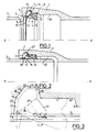
- la Figure 1 est une demi-vue en coupe axiale d'un joint à emboîtement conforme à l'invention avant l'introduction du bout mâle dans l'emboîtement ;
- la Figure 2 est une demi-vue analogue du joint à l'état monté ;
- la Figure 3 représente à plus grande échelle, également en coupe axiale, un détail des Figures 1 et 2 ; et
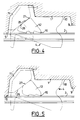
- les Figures 4 à 7 sont des vues analogues à la Figure 3 mais relatives à plusieurs variantes du joint suivant l'invention.
- On a représenté à la Figure 1 l'emboîtement 1 d'un premier tuyau et le bout mâle 2, à extrémité extérieurement chanfreinée en 3, d'un second tuyau, ainsi qu'une garniture d'étanchéité 4 à compression radiale et à inserts de verrouillage destinée à réaliser à la fois l'étanchéité et le verrouillage entre les deux tuyaux. Les deux tuyaux peuvent notamment être en fonte ductile.
- L'emboîtement 1 comporte une collerette de guidage 5, dont l'entrée est chanfreinée en 6, puis en allant vers le fond de l'emboîtement, une gorge d'ancrage 7, un évidement annulaire 8 de moindre profondeur, une collerette annulaire 9 en légère saillie radiale, et un logement terminal 10.
- La garniture 4 est constituée d'une masse d'élastomère surmoulée sur une couronne de paires d'inserts en matériau rigide, notamment métalliques, chaque paire comprenant un insert d'appui 11 et un insert d'accrochage 12 intérieurement denté. La garniture définit un corps avant 13, destiné à être comprimé radialement entre le bout mâle et le fond de l'évidement 8 et, à l'extrémité arrière (c'est-à-dire située du côté de l'entrée de l'emboîtement) de ce corps, un talon extérieur d'ancrage 14 et une lèvre d'étanchéité intérieure 15 servant à éviter l'introduction d'éléments extérieurs agressifs ou corrosifs dans la zone verrouillée. Chaque paire d'inserts 11, 12 est contenue dans un même demi-plan radial de la garniture, et ces paires sont régulièrement réparties sur le pourtour de cette dernière.
- Lorsque la garniture est mise en place dans l'emboîtement (Figure 1), la face radialement extérieure du corps 13 s'applique contre la surface périphérique de l'évidement 8, et le talon 14 est reçu dans la gorge 7, en laissant un espace libre radialement à l'extérieur et vers l'arrière. Dans cette situation, de même qu'à l'état libre de la garniture, la lèvre 15 est sensiblement radiale, et les dents des inserts 12 sont en saillie sur la face intérieure du corps 13 et sont sensiblement au contact des inserts 11, lesquels sont situés dans le talon 14 et affleurent la surface extérieure et arrière de l'élastomère. Ce positionnement des inserts 11 dans le talon d'ancrage 14 permet de rigidifier celui-ci et donc de renforcer l'effet d'ancrage dudit talon 14 dans la gorge 7 de l'emboîtement, augmentant en cela le maintien en place de la garniture 4 lors de l'introduction à force du bout mâle ou lors de la mise sous pression de la canalisation.
- Le montage du joint s'effectue par simple enfoncement axial du bout mâle dans l'emboîtement. Cette action replie la lèvre 15 vers l'avant, puis repousse radialement les inserts 11 et 12, ces derniers glissant le long des inserts 11, et comprime radialement le corps 13. On aboutit ainsi à la configuration de la Figure 2, où l'extrémité du bout mâle se trouve, avec un large jeu radial, dans l'évidement 10, où les inserts 11 sont bloqués dans la partie extérieure arrière de la gorge 7 et/ou les inserts 12 sont à la fois au contact de ces derniers et, par leurs dents 16, au contact du bout mâle.
- On a représenté sur la Figure 3 d'une part le contour de la garniture mise en place dans l'emboîtement, avant l'introduction du bout mâle, et d'autre part la position finale des paires d'inserts lorsqu'un bout mâle de diamètre maximal est en place dans l'emboîtement.
- Comme on le voit mieux sur cette Figure 3, la gorge 7 de l'emboîtement présente successivement, à partir de la collerette 5, une paroi 17 à peu près radiale et légèrement inclinée vers l'avant, une paroi 18 nettement plus inclinée, à environ 45°, un fond cylindrique 19, et une paroi avant 20 à peu près radiale et légèrement inclinée vers l'avant. Chaque insert 11 présente : vers l'arrière et à l'extérieur trois surfaces successives 21 à 23 conjuguées respectivement des surfaces 17 à 19 ; une surface intérieure 24 parallèle à l'axe X-X de l'emboîtement, qui est sensiblement l'axe du bout mâle et donc du joint, cette surface 24 se raccordant par un arrondi à l'extrémité intérieure de la surface 21 ; une surface 25 à peu près parallèle à la surface 20 et se raccordant par un arrondi à l'extrémité avant de la surface 23 ; et une rampe plane d'appui 26, dont l'inclinaison, vers le haut et vers le bas, est comprise entre 20 et 40° environ par rapport à l'axe X-X du joint, cette rampe reliant l'extrémité avant de la surface 24 à l'extrémité inférieure de la surface 25, les raccordements s'effectuant par des arrondis.
- Chaque insert 12 a une forme grossièrement quadrangulaire, avec une surface extérieure et arrière plane 27 et, à l'opposé de celle-ci, une surface intérieure d'accrochage définissant les trois dents 16 de l'insert. La surface 27 forme une rampe d'appui destinée à coopérer avec la rampe 26 de l'insert 11 associé. Avant l'introduction du bout mâle (Figure 1), la partie extérieure de la surface 27 se trouve en regard de la partie intérieure de la surface 26. Il en est de même lorsque la garniture est au repos.
- Au cours de l'introduction du bout mâle 2, la compression radiale de la garniture 4 a pour premier effet la mise en place des inserts 11 dans le coin extérieur arrière de la gorge 7, comme représenté sur les Figures 2 et 3, c'est-à-dire la venue des surfaces 21 à 23 en appui respectif contre les surfaces 17 à 19 de cette gorge. La position de la rampe 26 par rapport à l'emboîtement est ainsi parfaitement déterminée.
- De plus, l'introduction du bout mâle a pour effet de faire glisser la surface 27 des inserts 12 vers l'extérieur de long des rampes 26, de sorte que les inserts 12 se déplacent parallèlement à eux-mêmes jusqu'à une position qui dépend du diamètre réel du bout mâle dans le plan radial considéré. On a ainsi illustré à la Figure 3 les positions d'un insert 12 correspondant à un diamètre maximal du bout mâle (en trait plein) et à un diamètre minimal de ce bout mâle (en trait mixte).
- En pratique, les positions des inserts 11 et 12 décrites ci-dessus ne sont garanties qu'après la mise en pression de la canalisation.
- Les trois dents 16 sont usinées de façon que leurs pointes soient alignées sur une droite qui, lorsque les surfaces 27 et 26 coopèrent, est parallèle à l'axe X-X de l'emboîtement. Ainsi, quel que soit le diamètre du bout mâle, les trois dents attaquent simultanément ce bout mâle, et, lors du recul de celui-ci, la pression de contact est répartie entre elles de façon uniforme.
- Grâce à l'indépendance des paires d'inserts 11-12, les joints décrits ci-dessus peuvent accepter des déviations angulaires du bout mâle par rapport à l'emboîtement allant jusqu'à 5° environ.
- Il est à noter que quel que soit l'effort de recul s'exerçant sur le bout mâle, la réaction qui se développe sur chaque dent 16 de chaque insert 12 a une orientation déterminée, perpendiculaire à la surface 26, ce qui interdit un pivotement des inserts 12 risquant de perforer le bout mâle.
- En pratique, pour des tuyaux en fonte ductile ayant des diamètres courants, l'inclinaison des rampes 26 par rapport à l'axe de l'emboîtement est de préférence choisie entre 20 et 40° environ, comme indiqué plus haut. En effet, en-dessous de 20°, les tolérances diamétrales admises pour le bout mâle sont très faibles, et au-dessus de 40°, les inserts 12 s'accrochent mal sur le bout mâle et, par suite, le verrouillage est peu fiable.
- Les Figures 4 à 7 illustrent diverses variantes du joint des Figures 1 à 3.
- Dans le cas de la Figure 4, les surfaces 27 sont légèrement bombées, ce qui autorise de plus grandes déviations angulaires du bout mâle, pouvant aller jusqu'à 10° environ. En revanche, les pressions s'exerçant sur les trois dents sont différentes les unes des autres lors du recul du bout mâle, puisque les forces de réaction partent toutes de l'unique point de contact 28 entre les surfaces 26 et 27. Les mêmes remarques s'appliquent à une autre variante, non représentée, où ce sont les surfaces 26 qui sont légèrement bombées.
- La variante de la Figure 5 ne diffère de celle de la Figure 3 que par le fait que la dent 16 médiane est en retrait radial par rapport aux deux dents extrêmes. Ceci facilite l'accrochage des inserts 12 sur le bout mâle, car, pour un même effort, les pressions initiales, ne s'exerçant que sur deux dents au lieu de trois, sont plus élevées. Par contre, lorsque le recul du bout mâle est terminé, les pressions s'équilibrent entre les trois dents.
- De plus, dans cette variante, pour la même raison, il n'est pas nécessaire d'usiner les dents 16 pour leur donner un angle vif.
- Des remarques analogues peuvent s'appliquer à la variante de la Figure 6, où, au contraire, la dent 16 médiane est radialement saillante par rapport aux deux dents extrêmes, et à celle de la Figure 7, où c'est la dent 16 arrière qui est en retrait radial par rapport aux deux autres. Dans ce dernier cas, en outre, le repli vers l'avant de la lèvre 15 lors de l'introduction du bout mâle risque moins d'interférer avec la dent arrière des inserts.
- Dans chaque mode de réalisation, les inserts 11 et/ou 12 peuvent être isolés électriquement pour supprimer tout trajet de conduction électrique entre les deux tuyaux.
Claims (8)
- Joint à emboîtement entre tuyaux, comprenant un bout mâle (2) enfoncé dans un emboîtement (1) et une garniture d'étanchéité (4) comprimée radialement entre eux, la garniture comprenant un corps annulaire (13) en élastomère muni, du côté de l'entrée de l'emboîtement, d'un talon d'ancrage (14) en saillie extérieure logé dans une gorge d'ancrage (7) de l'emboîtement, et une couronne métallique (12) d'accrochage sur le bout mâle, noyée dans l'élastomère, caractérisé en ce qu'il comprend des organes d'appui (11) noyés dans l'élastomère du talon d'ancrage (14) de la garniture d'étanchéité (4) et ayant extérieurement une forme (21, 22, 23) conjuguée de celle (17, 18, 19) de la gorge d'ancrage (7) de l'emboîtement (1), ces organes d'appui (11) et la couronne d'accrochage (12) présentant des rampes coopérantes (26, 27) à profil au moins à peu près linéaire, inclinées par rapport à l'axe (X-X) du joint.
- Joint à emboîtement suivant la revendication 1, caractérisé en ce que les organes d'appui (11) et/ou la couronne d'accrochage (12) sont constitués par une série d'inserts en matériau rigide répartis sur le pourtour du joint.
- Joint à emboîtement suivant la revendication 1 ou 2, caractérisé en ce que, dans chaque plan radial où elle existe, la couronne d'accrochage (12) comprend plusieurs dents (16).
- Joint à emboîtement suivant la revendication 3, caractérisé en ce que les pointes de toutes les dents (16) sont alignées, ou peuvent s'aligner, sur une ligne parallèle à l'axe (X-X) de l'emboîtement lorsque les rampes coopérantes (26, 27) sont en appui mutuel.
- Joint à emboîtement suivant la revendication 3, caractérisé en ce que la pointe d'au moins une dent (16) intermédiaire est décalée radialement par rapport aux autres dents (16).
- Joint à emboîtement suivant la revendication 3, caractérisé en ce que la pointe d'au moins une dent (16) extrême est décalée radialement par rapport aux autres dents (16).
- Joint à emboîtement suivant l'une quelconque des revendications 1 à 6, caractérisé en ce que la pente, ou la pente moyenne, des rampes coopérantes (26, 27) est comprise entre environ 20° et environ 40° par rapport à l'axe (X-X) de l'emboîtement.
- Garniture d'étanchéité (4) à compression radiale et à couronne métallique d'accrochage (12) pour un joint à emboîtement suivant l'une quelconque des revendications 1 à 7, la garniture comprenant un corps annulaire (13) en élastomère muni d'un talon d'ancrage (14) en saillie extérieure, d'une couronne métallique (12) d'accrochage, noyée dans l'élastomère, et des organes d'appui (11) noyés dans l'élastomère du talon d'ancrage (14) de la garniture d'étanchéité (4), ces organes d'appui (11) et la couronne d'accrochage (12) présentant des rampes coopérantes (26, 27) à profil au moins à peu près linéaire, inclinées par rapport à l'axe (X-X) de la garniture.
Applications Claiming Priority (2)
| Application Number | Priority Date | Filing Date | Title |
|---|---|---|---|
| FR9200262 | 1992-01-13 | ||
| FR9200262A FR2686140B1 (fr) | 1992-01-13 | 1992-01-13 | Joint a emboitement entre tuyaux et garniture d'etancheite pour un tel joint. |
Publications (2)
| Publication Number | Publication Date |
|---|---|
| EP0552123A1 EP0552123A1 (fr) | 1993-07-21 |
| EP0552123B1 true EP0552123B1 (fr) | 1995-09-13 |
Family
ID=9425567
Family Applications (1)
| Application Number | Title | Priority Date | Filing Date |
|---|---|---|---|
| EP93470001A Expired - Lifetime EP0552123B1 (fr) | 1992-01-13 | 1993-01-11 | Joint à emboîtement entre tuyaux et garniture d'étanchéité pour un tel joint |
Country Status (21)
| Country | Link |
|---|---|
| US (1) | US5360218A (fr) |
| EP (1) | EP0552123B1 (fr) |
| JP (1) | JPH0737838B2 (fr) |
| AT (1) | ATE127893T1 (fr) |
| AU (1) | AU672766B2 (fr) |
| BR (1) | BR9300116A (fr) |
| CA (1) | CA2087045C (fr) |
| DE (1) | DE69300458T2 (fr) |
| DK (1) | DK0552123T3 (fr) |
| EE (1) | EE02965B1 (fr) |
| EG (1) | EG19788A (fr) |
| ES (1) | ES2070108T3 (fr) |
| FI (1) | FI930136A7 (fr) |
| FR (1) | FR2686140B1 (fr) |
| GR (1) | GR3017417T3 (fr) |
| LT (1) | LT3060B (fr) |
| LV (1) | LV10667B (fr) |
| MX (1) | MX9300113A (fr) |
| NO (1) | NO930076L (fr) |
| RU (1) | RU2080511C1 (fr) |
| ZA (1) | ZA9210104B (fr) |
Families Citing this family (51)
| Publication number | Priority date | Publication date | Assignee | Title |
|---|---|---|---|---|
| JP2576785Y2 (ja) * | 1993-02-22 | 1998-07-16 | 矢崎総業株式会社 | 防水コネクタの嵌合構造 |
| FR2708077B1 (fr) * | 1993-07-23 | 1995-09-22 | Pont A Mousson | Insert de verrouillage électriquement isolant pour garniture d'étanchéité, garniture d'étanchéité correspondante, et procédé de fabrication de tels inserts. |
| US5845945A (en) * | 1993-10-07 | 1998-12-08 | Carstensen; Kenneth J. | Tubing interconnection system with different size snap ring grooves |
| NL1009734C2 (nl) * | 1998-07-24 | 2000-01-25 | Fischer Georg Waga Nv | Koppelinrichting en werkwijze voor de vervaardiging van een in een dergelijke koppelinrichting te gebruiken gripring. |
| NL1002514C2 (nl) | 1996-03-04 | 1997-09-05 | Fischer Georg Waga Nv | Koppelinrichting. |
| GB2346422B (en) * | 1999-02-02 | 2003-04-23 | Glynwed Pipe Systems Ltd | A pipe coupling |
| SE519239C2 (sv) * | 1999-05-31 | 2003-02-04 | Enebacken Skrea Ab | Tätningsanordning för avtätning av en av två mot varandra vända tätningsytor bildad fog |
| US6499744B1 (en) * | 2000-06-05 | 2002-12-31 | S&B Technical Products, Inc. | Pipe gasket with dual purpose tail |
| US7108289B1 (en) | 2000-06-08 | 2006-09-19 | United States Pipe And Foundry Company, Llc | Restraining gasket for mechanical joints of pipes |
| US7104573B2 (en) * | 2000-06-08 | 2006-09-12 | United States Pipe And Foundy Company, Llc | Energized restraining gasket for mechanical joints of pipes |
| FR2820191B1 (fr) * | 2001-02-01 | 2004-01-30 | Saint Gobain Pont A Mousson | Garniture d'etancheite pour assemblage d'elements tubulaires de circuits de fluide |
| US6688652B2 (en) * | 2001-12-12 | 2004-02-10 | U.S. Pipe And Foundry Company | Locking device and method for securing telescoped pipe |
| DE20305711U1 (de) * | 2003-04-09 | 2003-08-28 | Buderus Guss Gmbh, 35576 Wetzlar | Zuggesicherte Muffenrohrverbindung |
| US20040232698A1 (en) * | 2003-05-19 | 2004-11-25 | Jim Jones | Self restraining gasket and pipe joint |
| US7125054B2 (en) * | 2003-05-19 | 2006-10-24 | S & B Technical Products, Inc. | Self restraining gasket and pipe joint |
| WO2005031174A2 (fr) * | 2003-09-25 | 2005-04-07 | United States Pipe And Foundry Company, Llc | Bague de compression a torsion centroide pour raccords de tuyaux |
| US7410174B2 (en) * | 2004-03-04 | 2008-08-12 | S & B Technical Products, Inc. | Restraining mechanical joint gasket for ductile iron pipe |
| US20050275217A1 (en) * | 2004-04-02 | 2005-12-15 | Star Pipe Products Ltd. | Mechanical joint gripping gasket |
| US7207606B2 (en) * | 2004-04-19 | 2007-04-24 | United States Pipe And Foundry Company, Llc | Mechanical pipe joint, gasket, and method for restraining pipe spigots in mechanical pipe joint bell sockets |
| FR2875888B1 (fr) * | 2004-09-24 | 2006-12-01 | Saint Gobain Pam Sa | Garniture d'etancheite et assemblage correspondant |
| US7815225B2 (en) * | 2005-06-10 | 2010-10-19 | S & B Technical Products, Inc. | Self restrained ductile iron fitting |
| US20100078937A1 (en) * | 2005-06-10 | 2010-04-01 | S & B Technical Products, Inc. | Self Restrained Ductile Iron Fitting |
| US8235427B2 (en) * | 2005-06-10 | 2012-08-07 | S & B Technical Products, Inc. | Self restrained ductile iron fitting |
| US20080001401A1 (en) * | 2006-05-25 | 2008-01-03 | Guido Quesada | Method and apparatus for preventing overinsertion in plastic pipe systems |
| USD557386S1 (en) * | 2006-05-30 | 2007-12-11 | S & B Technical Products, Inc. | Pipe gasket |
| USD559363S1 (en) * | 2006-05-30 | 2008-01-08 | S & B Technical Products, Inc. | Pipe gasket |
| US20080018017A1 (en) * | 2006-07-21 | 2008-01-24 | Guido Quesada | Modified transition angle in belled pipe |
| FR2907877B1 (fr) * | 2006-10-31 | 2012-06-22 | Saint Gobain Pont A Mousson | Jonction tubulaire |
| DE102007039582A1 (de) * | 2007-08-22 | 2009-02-26 | Knoch, Kern & Co. | Rohrkupplung |
| US20090273184A1 (en) * | 2008-04-30 | 2009-11-05 | Michael Wright | Self restrained joint for ductile iron pipe and fittings |
| WO2010102017A1 (fr) * | 2009-03-03 | 2010-09-10 | Mueller International, Inc. | Joint d'étanchéité pour une cloche taraudée |
| WO2011043836A1 (fr) * | 2009-10-09 | 2011-04-14 | Mueller International, Inc. | Dispositif d'étanchéité simplifié à faible force d'insertion apte à l'autolimitation et à la déviation de joint |
| US8857861B2 (en) | 2009-10-12 | 2014-10-14 | Mueller International, Llc | Self-restrained pipe joint system |
| MX2012013270A (es) | 2010-05-24 | 2013-08-27 | Mueller Int Llc | Dispositivo sellador simplificado de baja fuerza de insercion capaz de auto-restringir y desviar junta. |
| US9194519B2 (en) | 2010-08-24 | 2015-11-24 | Mueller International, Llc | Gasket for parabolic ramp self restraining bell joint |
| US8544851B2 (en) | 2010-08-24 | 2013-10-01 | Mueller International, Llc | Gasket for parabolic ramp self restraining bell joint |
| US8490273B1 (en) * | 2010-10-08 | 2013-07-23 | Mcwane Global | Pipe joint gasket and method of using same |
| RU2442061C1 (ru) * | 2010-10-21 | 2012-02-10 | Андрей Геннадьевич Винников | Муфта |
| FR2966554B1 (fr) * | 2010-10-26 | 2013-11-29 | Saint Gobain Pont A Mousson | Insert de verrouillage, garniture d'etancheite et assemblage correspondants |
| US9383049B2 (en) * | 2011-05-02 | 2016-07-05 | Cambridge Brass, Inc. | Universal coupling and parts therefor |
| DE102011082762A1 (de) | 2011-09-15 | 2013-03-21 | Airbus Operations Gmbh | Bewegliche Kupplung für eine Rohrleitung, Tankanordnung sowie Luft- oder Raumfahrzeug |
| AT511592B1 (de) * | 2011-09-19 | 2013-01-15 | E Hawle Armaturenwerke Gmbh | Rohrverbindungsvorrichtung und verfahren zu deren herstellung |
| US20140191504A1 (en) * | 2013-01-04 | 2014-07-10 | Yijun WU | PVC-Coated and Adaptive Pipe Coupling |
| US20140339823A1 (en) * | 2013-05-16 | 2014-11-20 | Infra-Tect, Llc | Beveled insert for facilitating coupling pipes |
| CH711285B1 (de) * | 2015-07-01 | 2019-02-15 | Marktmanagement Wild Ag | Schubsicherung für die Verbindung eines ersten Rohrabschnitts mit Anschlussmuffe mit einem zweiten Rohrabschnitt mit einem Einsteckende. |
| US10400924B2 (en) * | 2015-12-24 | 2019-09-03 | American Cast Iron Pipe Company | Pipe joint with low insertion load, improved retention and increased high pressure sealing ability gasket and method of manufacture thereof |
| US10352486B2 (en) * | 2015-12-24 | 2019-07-16 | American Cast Iron Pipe Company | Method of manufacturing a unitary gasket using two rubber materials of different hardness |
| US10648602B2 (en) | 2017-05-23 | 2020-05-12 | S&B Technical Products, Inc | Sealing gasket with specialized reinforcing ring for sealing plastic pipelines |
| US11965618B1 (en) | 2021-07-27 | 2024-04-23 | Hultec Acquisition, Llc | Pipe joint gasket and method of using same |
| USD1001980S1 (en) * | 2021-07-27 | 2023-10-17 | Mcwane, Inc. | Gasket segment |
| USD1001981S1 (en) * | 2021-07-27 | 2023-10-17 | Mcwane, Inc. | Gasket segment |
Family Cites Families (17)
| Publication number | Priority date | Publication date | Assignee | Title |
|---|---|---|---|---|
| US1930194A (en) * | 1930-06-28 | 1933-10-10 | Stephen V Dillon | Pipe coupling |
| US2201372A (en) * | 1938-11-26 | 1940-05-21 | Vernon Tool Co Ltd | Pipe coupling |
| DE2034325C3 (de) * | 1970-07-10 | 1974-03-07 | Georg 8000 Muenchen Seiler | Zug- und Schubsicherung für Steckmuffen- Verbindungen |
| DE2226151C2 (de) * | 1972-05-29 | 1974-06-27 | Georg 8000 Muenchen Seiler | Steckmuffenverbindung von Rohren oder Rohrelementen, insbesondere aus Metall |
| DE2606643B2 (de) * | 1976-02-19 | 1978-12-14 | Buderus Ag, 6300 Lahn-Wetzlar | Schubsichere Steckmuffen-Rohrverbindung |
| AT348838B (de) * | 1976-07-21 | 1979-03-12 | Straub Immanuel | Rohrkupplung |
| DE2754984A1 (de) * | 1977-12-09 | 1979-06-13 | Georg Seiler | Schub- und zugsicherung fuer rohrverbindungen |
| US4229026A (en) * | 1978-03-03 | 1980-10-21 | Eisenwerke Friedr. Wilh. Duker Gmbh & Co. | Socket connection for pipes and pipe elements |
| US4230325A (en) * | 1978-10-10 | 1980-10-28 | Butler Payson M | Conjugate two-piece packing ring with limiter |
| JPH0212189A (ja) | 1988-06-30 | 1990-01-17 | Toshiba Corp | 画像形成装置 |
| AU4822090A (en) | 1988-12-27 | 1990-08-01 | Robert M. Sanchez | Utility shutoff valve |
| US4911406A (en) | 1989-01-11 | 1990-03-27 | Accor Technology, Inc. | Fluid conduit coupling apparatus |
| FI892915A7 (fi) | 1989-06-14 | 1991-03-01 | Uponor Nv | Muhviliitoksen tiivistysrengas ja menetelmä muhviliitoksen aikaansaamiseksi |
| FR2649176B1 (fr) * | 1989-06-30 | 1994-03-25 | Pont A Mousson Sa | Garniture d'etancheite pour joints verrouilles etanches |
| US5219189A (en) * | 1989-12-11 | 1993-06-15 | Pont-A-Mousson S.A. | Composite gasket for the locked assembly of spigot and socket pipes |
| US5067751A (en) * | 1990-07-27 | 1991-11-26 | American Cast Iron Pipe Company | Gasket for field adaptable push-on restrained joint and joint thus produced |
| FR2679622B1 (fr) * | 1991-07-26 | 1994-09-30 | Pont A Mousson | Garniture d'etancheite composite pour assemblage verrouille de tuyaux, et assemblage verrouille correspondant. |
-
1992
- 1992-01-13 FR FR9200262A patent/FR2686140B1/fr not_active Expired - Fee Related
- 1992-12-30 ZA ZA9210104A patent/ZA9210104B/xx unknown
-
1993
- 1993-01-11 AT AT93470001T patent/ATE127893T1/de not_active IP Right Cessation
- 1993-01-11 EG EG1993A patent/EG19788A/xx active
- 1993-01-11 DK DK93470001.4T patent/DK0552123T3/da active
- 1993-01-11 EP EP93470001A patent/EP0552123B1/fr not_active Expired - Lifetime
- 1993-01-11 ES ES93470001T patent/ES2070108T3/es not_active Expired - Lifetime
- 1993-01-11 CA CA002087045A patent/CA2087045C/fr not_active Expired - Fee Related
- 1993-01-11 DE DE69300458T patent/DE69300458T2/de not_active Expired - Lifetime
- 1993-01-11 NO NO93930076A patent/NO930076L/no unknown
- 1993-01-11 MX MX9300113A patent/MX9300113A/es unknown
- 1993-01-12 AU AU31155/93A patent/AU672766B2/en not_active Ceased
- 1993-01-12 LV LVP-93-22A patent/LV10667B/en unknown
- 1993-01-12 LT LTIP283A patent/LT3060B/lt not_active IP Right Cessation
- 1993-01-12 RU RU9393004447A patent/RU2080511C1/ru active
- 1993-01-12 BR BR9300116A patent/BR9300116A/pt not_active IP Right Cessation
- 1993-01-12 US US08/003,509 patent/US5360218A/en not_active Expired - Fee Related
- 1993-01-12 JP JP5003559A patent/JPH0737838B2/ja not_active Expired - Lifetime
- 1993-01-13 FI FI930136A patent/FI930136A7/fi not_active Application Discontinuation
-
1994
- 1994-11-15 EE EE9400185A patent/EE02965B1/xx unknown
-
1995
- 1995-09-14 GR GR950402409T patent/GR3017417T3/el unknown
Also Published As
| Publication number | Publication date |
|---|---|
| NO930076L (no) | 1993-07-14 |
| EG19788A (en) | 1996-03-31 |
| EP0552123A1 (fr) | 1993-07-21 |
| AU672766B2 (en) | 1996-10-17 |
| DE69300458T2 (de) | 1996-03-07 |
| ES2070108T3 (es) | 1996-01-01 |
| FI930136L (fi) | 1993-07-14 |
| JPH05248576A (ja) | 1993-09-24 |
| EE02965B1 (et) | 1997-02-17 |
| CA2087045A1 (fr) | 1993-07-14 |
| US5360218A (en) | 1994-11-01 |
| NO930076D0 (no) | 1993-01-11 |
| DE69300458D1 (de) | 1995-10-19 |
| RU2080511C1 (ru) | 1997-05-27 |
| FI930136A7 (fi) | 1993-07-14 |
| ATE127893T1 (de) | 1995-09-15 |
| BR9300116A (pt) | 1993-07-20 |
| LTIP283A (lt) | 1994-03-25 |
| GR3017417T3 (en) | 1995-12-31 |
| LV10667B (en) | 1995-08-20 |
| LT3060B (en) | 1994-10-25 |
| LV10667A (lv) | 1995-04-20 |
| MX9300113A (es) | 1993-07-01 |
| FI930136A0 (fi) | 1993-01-13 |
| CA2087045C (fr) | 1996-12-17 |
| DK0552123T3 (da) | 1996-02-05 |
| JPH0737838B2 (ja) | 1995-04-26 |
| FR2686140A1 (fr) | 1993-07-16 |
| ES2070108T1 (es) | 1995-06-01 |
| AU3115593A (en) | 1993-08-05 |
| ZA9210104B (en) | 1993-08-03 |
| FR2686140B1 (fr) | 1995-05-24 |
Similar Documents
| Publication | Publication Date | Title |
|---|---|---|
| EP0552123B1 (fr) | Joint à emboîtement entre tuyaux et garniture d'étanchéité pour un tel joint | |
| CA2243425C (fr) | Dispositif pour l'assemblage de deux elements de canalisation, et assemblages d'elements de canalisation en comportant application | |
| EP0541472B1 (fr) | Joint verrouillé pour canalisations | |
| EP0310534B1 (fr) | Garniture d'étanchéité pour joints verrouillés télescopiques | |
| EP0911565B1 (fr) | Connexion rapide pour emmanchement d'un tube rigide dans un embout | |
| FR2493467A1 (fr) | Dispositif de raccordement hydraulique a accouplement rapide | |
| WO1996017201A1 (fr) | Dispositif de raccordement rapide d'un tube a un embout rigide | |
| EP2633218B1 (fr) | Assemblage avec garniture d'étanchéité avec insert de verrouillage. | |
| FR2737275A1 (fr) | Raccord de tuyaux antiseparation | |
| EP1792110B1 (fr) | Garniture d'etancheite et assemblage correspondant | |
| EP0526373B1 (fr) | Assemblage verrouillé de tuyaux avec garniture d'étanchéité composite | |
| EP0653034B1 (fr) | Joint verrouille a emboitement entre elements tubulaires | |
| FR2770612A1 (fr) | Joint a rotule pour l'assemblage etanche de deux elements de canalisation | |
| EP0470918B1 (fr) | Joint entre éléments de tuyauterie | |
| EP0581678B1 (fr) | Tuyau muni d'un dispositif de serrage radial pour raccordement à une extrémité de tuyau; embout de raccordement comprenant ce tuyau | |
| FR2867251A1 (fr) | Raccord a sertir comprenant une bague de visualisation secable | |
| EP4227566B1 (fr) | Elément femelle de raccord fluidique et raccord fluidique comprenant un tel élément | |
| FR2866094A1 (fr) | Raccord mecanique destine a assurer la solidarisation d'un tuyau en matiere plastique a un appareil de robinetterie | |
| EP4153894B1 (fr) | Assemblage etanche et verrouille | |
| EP0890775B1 (fr) | Dispositif de verrouillage pour un assemblage de deux éléments de canalisation, et assemblage d'éléments de canalisation en comportant application. | |
| CH600204A5 (en) | Lip seal for telescopic pipe joint | |
| FR2684163A1 (fr) | Dispositif de bagues d'etancheite formant joint pour raccordement souple entre deux elements. |
Legal Events
| Date | Code | Title | Description |
|---|---|---|---|
| PUAI | Public reference made under article 153(3) epc to a published international application that has entered the european phase |
Free format text: ORIGINAL CODE: 0009012 |
|
| AK | Designated contracting states |
Kind code of ref document: A1 Designated state(s): AT BE CH DE DK ES FR GB GR IE IT LI LU MC NL PT SE |
|
| 17P | Request for examination filed |
Effective date: 19940114 |
|
| 17Q | First examination report despatched |
Effective date: 19950302 |
|
| GRAA | (expected) grant |
Free format text: ORIGINAL CODE: 0009210 |
|
| AK | Designated contracting states |
Kind code of ref document: B1 Designated state(s): AT BE CH DE DK ES FR GB GR IE IT LI LU MC NL PT SE |
|
| REF | Corresponds to: |
Ref document number: 127893 Country of ref document: AT Date of ref document: 19950915 Kind code of ref document: T |
|
| ITF | It: translation for a ep patent filed | ||
| REG | Reference to a national code |
Ref country code: IE Ref legal event code: FG4D Free format text: 65224 |
|
| GBT | Gb: translation of ep patent filed (gb section 77(6)(a)/1977) |
Effective date: 19950918 |
|
| REF | Corresponds to: |
Ref document number: 69300458 Country of ref document: DE Date of ref document: 19951019 |
|
| REG | Reference to a national code |
Ref country code: GR Ref legal event code: FG4A Free format text: 3017417 |
|
| SC4A | Pt: translation is available |
Free format text: 950913 AVAILABILITY OF NATIONAL TRANSLATION |
|
| REG | Reference to a national code |
Ref country code: ES Ref legal event code: FG2A Ref document number: 2070108 Country of ref document: ES Kind code of ref document: T3 |
|
| REG | Reference to a national code |
Ref country code: DK Ref legal event code: T3 |
|
| PLBE | No opposition filed within time limit |
Free format text: ORIGINAL CODE: 0009261 |
|
| STAA | Information on the status of an ep patent application or granted ep patent |
Free format text: STATUS: NO OPPOSITION FILED WITHIN TIME LIMIT |
|
| 26N | No opposition filed | ||
| PGFP | Annual fee paid to national office [announced via postgrant information from national office to epo] |
Ref country code: MC Payment date: 19961217 Year of fee payment: 5 |
|
| PGFP | Annual fee paid to national office [announced via postgrant information from national office to epo] |
Ref country code: AT Payment date: 19961220 Year of fee payment: 5 Ref country code: DK Payment date: 19961220 Year of fee payment: 5 |
|
| PGFP | Annual fee paid to national office [announced via postgrant information from national office to epo] |
Ref country code: NL Payment date: 19961223 Year of fee payment: 5 Ref country code: GR Payment date: 19961223 Year of fee payment: 5 |
|
| PGFP | Annual fee paid to national office [announced via postgrant information from national office to epo] |
Ref country code: IE Payment date: 19970108 Year of fee payment: 5 |
|
| PGFP | Annual fee paid to national office [announced via postgrant information from national office to epo] |
Ref country code: PT Payment date: 19970109 Year of fee payment: 5 |
|
| PGFP | Annual fee paid to national office [announced via postgrant information from national office to epo] |
Ref country code: SE Payment date: 19970123 Year of fee payment: 5 |
|
| PGFP | Annual fee paid to national office [announced via postgrant information from national office to epo] |
Ref country code: CH Payment date: 19970203 Year of fee payment: 5 |
|
| PGFP | Annual fee paid to national office [announced via postgrant information from national office to epo] |
Ref country code: LU Payment date: 19970206 Year of fee payment: 5 |
|
| PGFP | Annual fee paid to national office [announced via postgrant information from national office to epo] |
Ref country code: BE Payment date: 19970217 Year of fee payment: 5 |
|
| PG25 | Lapsed in a contracting state [announced via postgrant information from national office to epo] |
Ref country code: LU Free format text: LAPSE BECAUSE OF NON-PAYMENT OF DUE FEES Effective date: 19980111 Ref country code: IE Free format text: LAPSE BECAUSE OF NON-PAYMENT OF DUE FEES Effective date: 19980111 Ref country code: AT Free format text: LAPSE BECAUSE OF NON-PAYMENT OF DUE FEES Effective date: 19980111 |
|
| PG25 | Lapsed in a contracting state [announced via postgrant information from national office to epo] |
Ref country code: SE Free format text: LAPSE BECAUSE OF NON-PAYMENT OF DUE FEES Effective date: 19980112 |
|
| PG25 | Lapsed in a contracting state [announced via postgrant information from national office to epo] |
Ref country code: LI Free format text: LAPSE BECAUSE OF NON-PAYMENT OF DUE FEES Effective date: 19980131 Ref country code: GR Free format text: LAPSE BECAUSE OF NON-PAYMENT OF DUE FEES Effective date: 19980131 Ref country code: CH Free format text: LAPSE BECAUSE OF NON-PAYMENT OF DUE FEES Effective date: 19980131 Ref country code: BE Free format text: LAPSE BECAUSE OF NON-PAYMENT OF DUE FEES Effective date: 19980131 |
|
| PG25 | Lapsed in a contracting state [announced via postgrant information from national office to epo] |
Ref country code: DK Free format text: LAPSE BECAUSE OF NON-PAYMENT OF DUE FEES Effective date: 19980202 |
|
| BERE | Be: lapsed |
Owner name: S.A. PONT-A-MOUSSON Effective date: 19980131 |
|
| PG25 | Lapsed in a contracting state [announced via postgrant information from national office to epo] |
Ref country code: PT Free format text: LAPSE BECAUSE OF NON-PAYMENT OF DUE FEES Effective date: 19980731 Ref country code: MC Free format text: LAPSE BECAUSE OF NON-PAYMENT OF DUE FEES Effective date: 19980731 |
|
| PG25 | Lapsed in a contracting state [announced via postgrant information from national office to epo] |
Ref country code: NL Free format text: LAPSE BECAUSE OF NON-PAYMENT OF DUE FEES Effective date: 19980801 |
|
| REG | Reference to a national code |
Ref country code: CH Ref legal event code: PL |
|
| NLV4 | Nl: lapsed or anulled due to non-payment of the annual fee |
Effective date: 19980801 |
|
| EUG | Se: european patent has lapsed |
Ref document number: 93470001.4 |
|
| REG | Reference to a national code |
Ref country code: PT Ref legal event code: MM4A Free format text: LAPSE DUE TO NON-PAYMENT OF FEES Effective date: 19980731 |
|
| REG | Reference to a national code |
Ref country code: DK Ref legal event code: EBP |
|
| REG | Reference to a national code |
Ref country code: GB Ref legal event code: IF02 |
|
| PGFP | Annual fee paid to national office [announced via postgrant information from national office to epo] |
Ref country code: IT Payment date: 20100115 Year of fee payment: 18 Ref country code: FR Payment date: 20100208 Year of fee payment: 18 |
|
| REG | Reference to a national code |
Ref country code: FR Ref legal event code: ST Effective date: 20110930 |
|
| PG25 | Lapsed in a contracting state [announced via postgrant information from national office to epo] |
Ref country code: FR Free format text: LAPSE BECAUSE OF NON-PAYMENT OF DUE FEES Effective date: 20110131 |
|
| PG25 | Lapsed in a contracting state [announced via postgrant information from national office to epo] |
Ref country code: IT Free format text: LAPSE BECAUSE OF NON-PAYMENT OF DUE FEES Effective date: 20110111 |
|
| PGFP | Annual fee paid to national office [announced via postgrant information from national office to epo] |
Ref country code: DE Payment date: 20120104 Year of fee payment: 20 |
|
| PGFP | Annual fee paid to national office [announced via postgrant information from national office to epo] |
Ref country code: GB Payment date: 20120111 Year of fee payment: 20 |
|
| REG | Reference to a national code |
Ref country code: DE Ref legal event code: R071 Ref document number: 69300458 Country of ref document: DE |
|
| REG | Reference to a national code |
Ref country code: GB Ref legal event code: PE20 Expiry date: 20130110 |
|
| PG25 | Lapsed in a contracting state [announced via postgrant information from national office to epo] |
Ref country code: GB Free format text: LAPSE BECAUSE OF EXPIRATION OF PROTECTION Effective date: 20130110 Ref country code: DE Free format text: LAPSE BECAUSE OF EXPIRATION OF PROTECTION Effective date: 20130112 |
|
| PGFP | Annual fee paid to national office [announced via postgrant information from national office to epo] |
Ref country code: ES Payment date: 20120213 Year of fee payment: 20 |
|
| REG | Reference to a national code |
Ref country code: ES Ref legal event code: FD2A Effective date: 20130715 |
|
| PG25 | Lapsed in a contracting state [announced via postgrant information from national office to epo] |
Ref country code: ES Free format text: LAPSE BECAUSE OF EXPIRATION OF PROTECTION Effective date: 20130112 |