EP0552126A2 - Innengefaltete Streckmetallelektrode für Batteriekonstruktion - Google Patents
Innengefaltete Streckmetallelektrode für Batteriekonstruktion Download PDFInfo
- Publication number
- EP0552126A2 EP0552126A2 EP93630002A EP93630002A EP0552126A2 EP 0552126 A2 EP0552126 A2 EP 0552126A2 EP 93630002 A EP93630002 A EP 93630002A EP 93630002 A EP93630002 A EP 93630002A EP 0552126 A2 EP0552126 A2 EP 0552126A2
- Authority
- EP
- European Patent Office
- Prior art keywords
- substrate
- frame
- battery
- grid
- stack
- Prior art date
- Legal status (The legal status is an assumption and is not a legal conclusion. Google has not performed a legal analysis and makes no representation as to the accuracy of the status listed.)
- Withdrawn
Links
Images

Classifications
-
- H—ELECTRICITY
- H01—ELECTRIC ELEMENTS
- H01M—PROCESSES OR MEANS, e.g. BATTERIES, FOR THE DIRECT CONVERSION OF CHEMICAL ENERGY INTO ELECTRICAL ENERGY
- H01M10/00—Secondary cells; Manufacture thereof
- H01M10/06—Lead-acid accumulators
- H01M10/18—Lead-acid accumulators with bipolar electrodes
-
- H—ELECTRICITY
- H01—ELECTRIC ELEMENTS
- H01M—PROCESSES OR MEANS, e.g. BATTERIES, FOR THE DIRECT CONVERSION OF CHEMICAL ENERGY INTO ELECTRICAL ENERGY
- H01M4/00—Electrodes
- H01M4/02—Electrodes composed of, or comprising, active material
- H01M4/14—Electrodes for lead-acid accumulators
-
- H—ELECTRICITY
- H01—ELECTRIC ELEMENTS
- H01M—PROCESSES OR MEANS, e.g. BATTERIES, FOR THE DIRECT CONVERSION OF CHEMICAL ENERGY INTO ELECTRICAL ENERGY
- H01M4/00—Electrodes
- H01M4/02—Electrodes composed of, or comprising, active material
- H01M4/64—Carriers or collectors
- H01M4/70—Carriers or collectors characterised by shape or form
- H01M4/72—Grids
- H01M4/73—Grids for lead-acid accumulators, e.g. frame plates
-
- H—ELECTRICITY
- H01—ELECTRIC ELEMENTS
- H01M—PROCESSES OR MEANS, e.g. BATTERIES, FOR THE DIRECT CONVERSION OF CHEMICAL ENERGY INTO ELECTRICAL ENERGY
- H01M50/00—Constructional details or processes of manufacture of the non-active parts of electrochemical cells other than fuel cells, e.g. hybrid cells
- H01M50/10—Primary casings; Jackets or wrappings
-
- H—ELECTRICITY
- H01—ELECTRIC ELEMENTS
- H01M—PROCESSES OR MEANS, e.g. BATTERIES, FOR THE DIRECT CONVERSION OF CHEMICAL ENERGY INTO ELECTRICAL ENERGY
- H01M50/00—Constructional details or processes of manufacture of the non-active parts of electrochemical cells other than fuel cells, e.g. hybrid cells
- H01M50/30—Arrangements for facilitating escape of gases
- H01M50/317—Re-sealable arrangements
- H01M50/325—Re-sealable arrangements comprising deformable valve members, e.g. elastic or flexible valve members
-
- Y—GENERAL TAGGING OF NEW TECHNOLOGICAL DEVELOPMENTS; GENERAL TAGGING OF CROSS-SECTIONAL TECHNOLOGIES SPANNING OVER SEVERAL SECTIONS OF THE IPC; TECHNICAL SUBJECTS COVERED BY FORMER USPC CROSS-REFERENCE ART COLLECTIONS [XRACs] AND DIGESTS
- Y02—TECHNOLOGIES OR APPLICATIONS FOR MITIGATION OR ADAPTATION AGAINST CLIMATE CHANGE
- Y02E—REDUCTION OF GREENHOUSE GAS [GHG] EMISSIONS, RELATED TO ENERGY GENERATION, TRANSMISSION OR DISTRIBUTION
- Y02E60/00—Enabling technologies; Technologies with a potential or indirect contribution to GHG emissions mitigation
- Y02E60/10—Energy storage using batteries
-
- Y—GENERAL TAGGING OF NEW TECHNOLOGICAL DEVELOPMENTS; GENERAL TAGGING OF CROSS-SECTIONAL TECHNOLOGIES SPANNING OVER SEVERAL SECTIONS OF THE IPC; TECHNICAL SUBJECTS COVERED BY FORMER USPC CROSS-REFERENCE ART COLLECTIONS [XRACs] AND DIGESTS
- Y02—TECHNOLOGIES OR APPLICATIONS FOR MITIGATION OR ADAPTATION AGAINST CLIMATE CHANGE
- Y02P—CLIMATE CHANGE MITIGATION TECHNOLOGIES IN THE PRODUCTION OR PROCESSING OF GOODS
- Y02P70/00—Climate change mitigation technologies in the production process for final industrial or consumer products
- Y02P70/50—Manufacturing or production processes characterised by the final manufactured product
Definitions
- the present invention relates generally to the art of batteries and more particularly to sealed, high-power lead-acid batteries of a modified bipolar nature. Still more specifically, in the most preferred embodiment, the invention relates to a battery which includes a expanded metal grid inserted through slots in a non-conductive film and folded therearound prior to pasting to form individual quasi bipolar battery elements.
- Bipolar batteries have been known for many years and typically include an electrode pair constructed such that positive and negative active materials are disposed on opposite sides of an electronically conductive plate. Batteries prepared from bipolar electrodes typically comprise a series arrangement of the electrodes, with separate elements for the terminal electrodes, which are typically monopolar in nature.
- bipolar electrodes are compared to monopolar batteries, the latter being typified by automotive batteries.
- monopolar systems electrodes of like polarity are usually connected by means of a lead lug, with monopolar cells connected in series using intercell welds.
- the cell-to-cell discharge path is comparatively shorter and dispersed over a larger cross-sectional area, thus reducing the ohmic resistance and improving power capabilities.
- operating voltages of bipolar batteries should be considerably higher due to the lower resistance, providing the capability of producing high voltage batteries in relatively small, light-weight packages.
- Lead-acid batteries are attractive candidates for bipolar construction because of the high power capabilities known chemistry, excellent thermal characteristics, safe operation and widespread use.
- the key component, however, in the development of lead-acid bipolar batteries has been the bipolar substrate construction. That element must be non-porous and must be able to withstand the corrosive environment within the lead-acid battery enclosure.
- light-weight batteries include continuous strips of thermoplastic material and a plurality of electrically isolated lead strip arrays about which the strips are folded to provide pleated bipolar plates. The strips are sealed along their edges for receiving separator plates and so that electrolyte may be maintained within the cells.
- the active material for the battery is carried in scrim fabric and the entire assembly is held under compression by exterior resilient means.
- a "Secondary Battery” is described in McCullough, et al., United States Patent No. 4,830,938, issued May 16, 1989, and includes a series of cells defined by electrodes having a body length sufficient to be inserted through an insulating wall into adjacent cells, the electrode extending from the bottom of one cell, through the insulator at a location near the top of the electrode and into the next cell.
- the electrodes are electrically conductive carbonaceous material having defined properties which act as energy storing material.
- the batteries are interconnected by means of a pair of conductive bands insulated from one another and bent into a zig-zag formation. Each band overlays an electrode of one polarity, thus performing the function of a separator as well as a terminal conductor.
- the conductive strips are made from a material such as stainless steel.
- the present invention features a quasi-bipolar battery element which overcomes numerous disadvantages of prior art devices.
- the invention features a battery element which is capable of being combined with other elements to form high-power, lead-acid batteries having high voltage and current output.
- the invention also features a battery element which achieves numerous bipolar benefits without using a conductive bipolar substrate.
- the invention further features battery elements for which the current flow path is short, while retaining large surface areas for the active battery material.
- the invention also features battery elements which can be constructed in a variety of shapes and combined in a variety of series and parallel arrangements to provide batteries having widely varying power and application characteristics.
- a battery element which includes a frame supporting a non-conductive sheet which includes one or more slots therein.
- the grid for the battery of the preferred form of the present invention includes an expanded metal, lead grid which is folded and passed through the slots so that a portion of the grid lays against opposite faces of the sheet.
- the slot and fold area is sealed to prevent leakage from one side of the sheet to another during use of the element, and the grids are pasted with active materials, which may be conventional in and of themselves.
- the electrodes are combined, with appropriate separators, terminal plates, and battery casings to provide a completed battery. Addition of electrolyte and formation then takes place, and vents are provided for each cell to prevent the build-up of dangerously high pressures within the cells.
- the current flow path may be decreased by expanding the number of slots and the number of grids for a given size electrode.
- FIGURES Before proceeding to the description of the FIGURES, details of the preferred embodiment of the present invention and its method of fabrication, it will be useful to provide general comments about the applicability and adaptability of the present invention.
- a unitary component made by injection molding or other techniques could be employed.
- the disclosed embodiment shows the two components because we have found it to be superior from a manufacturing and from a reliability standpoint.
- the present invention is illustrated as including an expanded metal grid, namely an expanded lead grid
- other materials known to provide support for battery paste materials may be used in the present invention.
- numerous lead alloys and other metals and alloys are well known in the lead-acid battery art, and they could be employed in the present invention.
- the electrode elements of the present invention are prepared by employing two folded, coined expanded lead grids, yielding four separate flow paths, as will become apparent shortly.
- a greater number of grids could be used for the size of frame which will be illustrated, or a single, folded grid could be used.
- the more folds for the same plate area the greater the number of distinct flow paths, each having a shorter pathway, resulting in reduced ohmic resistance.
- the paste materials which are useful in the present invention for the positive and negative sides of the electrodes can be selected from any conventional lead-acid pastes. Any known lead-acid paste materials could be substituted, including doped systems.
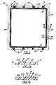
- Frame 10 is preferably formed by a molding process (e.g., injection molding) from a thermoplastic resin suitable for use in the harsh environments encountered in lead-acid batteries.
- a molding process e.g., injection molding
- Polyolefins are appropriate, such as polyethylene or polypropylene, with high density polyethylene reinforced with about 30% glass fibers being used in our most recent work.
- Frame 10 may be made in various sizes, but to give the reader some idea of one preferred construction, frame 10 is square and has sides of about 12 inches.
- Frame 10 as the name implies, includes a border 12 surrounding a square opening 14.
- the thickness of frame 10 is about 0.10'' and the width of the border is about 0.90'' in the illustrated embodiment.
- Frame 10 includes several other features including an inwardly directed lip 16 surrounding opening 14 and extending from the rear of frame 10 as it is viewed in this FIGURE.
- a first raised bead 20 extends outwardly from the front surface of frame 10 and totally surrounds the opening 14 at a location outwardly of, but generally near lip 16.
- a pair of recesses 22 and 23 are located on either side of bead 20. They similarly extend around the border 12 of frame 10.
- a hole 24 is shown in the FIGURE at approximately the middle of each side of border 12, located between recess 23 and the outer edge of border 12.
- four channel moldings 26 are formed on each of two opposing sides (25 and 27) of frame 10 by a pair of parallel beads 28 having a height coextensive with that of bead 20.
- Grooves 29 are formed in the border 12 on both sides of beads 28 and extending from the outer edge of border 12 toward opening 14, but the grooves 29 do not interrupt the integrity of bead 20.
- a channel 31 is formed between and generally parallel to beads 28, channel 31 having a depth greater than grooves 29. Channel 31 extends from the outside of border 12 but also does not pass through bead 20.
- Each frame 10 will be a building block for a battery electrode, with a film (soon to be described) joined to lip 16, and with battery grid and active materials in turn secured to the film.
- the frames 10, a selected number of which will be used for a particular application, will be joined to one another in a front-to-back relationship (shown in later FIGURES) so that the bead 20 and the beads 28 of one frame 10 will attach to the generally planar rear surface of the next frame.
- the bead height, as well as the thickness of the frames, will therefore define individual cells for containing electrode, electrolyte and separator components.
- one of the channels 31 will eventually be used as a passageway and be coupled to a filler tube to permit addition and removal of electrolyte from the cells during battery formation and to receive a vent to prevent gas ingress and to permit release of excessive gas pressure from within the cells. It will, of course, not be necessary or desirable to use all of the channels 31 which could be used (eight in the FIGURES), but it may be desirable in a cell stack to vary the location of the opened channel from one cell to the next. This is why four channels are provided in a spaced apart pattern across the sides 25 and 27 of frame 10.
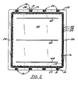
- Substrate 40 can also be made from glassed-filled high density polyethylene (or the other materials referred to above for use in constructing frame 10), with the preferred material being 15% glass filled HDPE and having a thickness of about 0.020''. It can also be seen in FIGURE 2 that three parallel slots 42-44 are cut through substrate 40, one near side 25, one in the middle of the substrate 40 and one adjacent to the opposite side 27. The slots have a width of about 0.60'' and, as will be explained below, are arranged to receive folded battery grids.
- the present invention encompasses using only a single slot adjacent one side with a single fold of grid material, or more than three slots for some applications.
- the substrate 40 is connected to frame 10 in the most preferred embodiment using a heat welding technique, such as IR welding.
- the substrate 40 is sized to overlay lip 16 and to be received within frame 10.
- Masking tape or any other type of adhesive can be used to maintain the substrate 40 in a proper fixed location during welding.
- frame 10 and substrate 40 could be formed as a single component, but we have determined the above-described two-component fabrication technique is most suitable. Some attempts to form the components in a unitary fashion resulted in leakage and failure, possibly due to the different cooling rates of components having different thicknesses, (i.e. the substrate area versus the frame area). Moreover, use of the above-described fabrication technique allows for the selection of different materials for frame 10 and substrate 40, which may provide cost or other benefits.
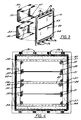
- the grids 50 (shown first in FIGURE 3) to be added to the structure shown in FIGURE 2 will now be described. As previously mentioned, they are preferably lead grids and are most preferably expanded lead grids. Two suitable materials are available from Delker Corporation of Branford, Connecticut, Type #416 with 6.67Xlength extension and 85% open area or Type #284 with 3.33Xlength extension and 70% open area.
- the grid material Prior to adding the grids to the substrate, the grid material is cut to the approximate length from the roll on which it is provided by the supplier. The material is then placed in a coining press to create the desired thickness of the expanded metal which will eventually receive the positive and negative active paste materials. While a single thickness could be used, our work has indicated that a different thickness for the positive and negative sides yields improved results. Accordingly, in the preferred embodiment, the area of grid 50 which will receive positive paste material is coined to a thickness of about 0.035'', while the area which is to receive negative paste material is coined to about 0.020''. Both dimensions could be varied depending on battery size. For our preferred embodiment, we used about 42 grams of the #416 material and the coining press was a 100 ton press, with coining time of about 15 seconds.
- Grids 50 are folded as shown in FIGURE 3, it being appreciated now that the positive paste receiving area will be the folded flaps 52, while the negative paste receiving area will be the planar area 53 (or vice versa for both).
- the grids 50 are preferably cleaned during this phase of the process (e.g. in a 1,1,1-trichloroethane solution) and dried, following which the area of the folds are coated with a film of a wood resin based material (which can be dissolved in 1,1,1-TCE) to act as a corrosion inhibitor.
- FIGURE 4 a front elevational view, the grid flaps 52 are shown folded into contact with the front surface of substrate 40. Moreover, the area 53 on the reversed side of substrate 40 is slit across its width, in each instance at a location opposite to that of the adjoining edges of flaps 52.
- the result, using the three slot substrate and two folded grids 50 is the creation of four individual grid elements 51 having a flap 52 on one side of the substrate and a newly created flap on the opposite side of the substrate 40.
- Any suitable shearing device such as a knife or scissors, can be used to form the rear flaps from the initial planar areas 53.
- the next step in the fabrication process of the preferred embodiment of the present invention is the sealing of the fold/slot area 57.
- This is preferably accomplished using a thermal welding technique, such as IR welding, after the flaps have been adhered on the proper location on substrate 40, e.g., by the use of several drops of a hot melted adhesive or by the use of a sheet of double-sided adhesive tape.
- the sealing material itself can be narrow strips 58 of the same material from which the substrate was initially prepared having a width of, for example, 0.030''.
- the strip 58 would be tacked on each end using a hot tool such as a soldering iron, following which the IR welder causes the strip 58 to melt down into the grid and seal the slots 42-44 on one side.
- the same procedure is employed on the opposite side of the substrate, following which leak testing is performed using known techniques to insure adequate sealing of each grid.
- a nitrogen tester in a bubble chamber is one suitable technique for performing such testing.
- the test fixture should be set to at least five PSI and the electrode should produce zero bubbling after 60 seconds. Leaks which are noted can be repaired using the welding or melting techniques previously described.
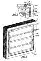
- FIGURE 5 a partial view of an upper corner of the electrode 60 (comprising the frame 10, substrate 40 and sealed grids 50) with paste material 62 applied thereto. It should also be noted in this figure that a channel 31 has been opened (for example, by using a hot needle or wire).
- the elements 60 are prepared for pasting by final cleaning steps which can include washing with water and if necessary light scrubbing with a small brush. A rinse in 1,1,1,-TCE is followed by complete drying. Using a masking tape, such as drafting tape, both sides of element 60 are masked to define the area which is to receive the pastes.
- the tape keeps the areas which will subsequently be welded together as clean as possible and reduces the amount of electrode clean-up which is required prior to final assembly.
- pasted electrode elements 70 ready for assembly into a battery stack.
- the channel 31 which has been opened is the one at the upper, right-hand corner in this view.
- pasted electrodes 70 will have a sequential arrangement of channel openings.
- FIGURE 6 is a perspective view of a plate stack 75 which includes 20 of elements 70 connected together in a manner which will be described shortly. As shown in FIGURE 6, the cell stack is still square.
- the stack 75 is prepared by first making sure that all grids of the electrode elements 70 are flat and that no rough edges of the expanded metal extend angularly to the substrate which could result in shorting of the electrodes.
- CELGARD 3501 which is supplied by Hoechst Celanese Corporation for this purpose.
- separator sheets 76 will be disposed between adjoining positive and negative faces in the cell stack.
- the selection of the separator material can be from those used in the lead-acid battery art, but we prefer to use absorptive glass mat separators such as Hovosorb 2 BG-14017 sold by Hollingsworth and Vose Company.
- This separator material has a surface area of approximately one square meter per gram and includes approximately 5% hydrophobic filler such as polypropylene.
- the separator sheets should be sufficiently large to cover all paste areas and yet not interfere with the welding which will take place using beads 20 and 28.
- the stacking procedure is started, in our preferred fabrication technique, by placing one electrode 70 in a fixture which will ensure proper alignment of the electrodes 70 as they are added into stack 75. Between the first electrode and the second, a separator sheet is added and tacked in place, for example using several small drops of hot melt adhesive.
- a separator sheet is added and tacked in place, for example using several small drops of hot melt adhesive.
- the procedure is continued by welding additional electrodes 70 onto the stack until the desired number has been reached.
- FIGURE 7 is a perspective view of the upper portion of the element stack 75 shown in FIGURE 6 and illustrating the preparation of the acid flow ports. It will be noted in this figure that a square cavity 76 has been milled around the area of channel moldings 26 using normal plastic milling equipment, the stack 75 being held in position by clamping devices. It should also be noted that four separate rows of frame material 77-80 are left along the top, each of the rows including five of the open channels 31 previously discussed. This is accomplished during the cell stacking and vibration welding procedures by selecting appropriate elements 70 having the desired open channel location. This particular arrangement is beneficial because it provides additional room for the acid flow fill ports and the vent devices which will be described later, i.e. five in each row, rather than having to arrange 20 of the devices in a smaller amount of space.
- Frame 10 could be varied to provide five channels, or any other arrangement might be used.
- the channels 31 are cleared using a small drill bit, for example, and a vacuum may be applied to ensure that there is no internal contamination of the cells formed between adjacent elements 70.
- Each of 20 flow ports 88 are then provided with a fitting 89 which is secured in place, for example, using an epoxy resin.
- the fittings 89 are simple plastic tubes, tapered somewhat to be received within the flow ports 88 provided above each open channel 31.
- An epoxy resin which can be used is H.B. Fuller UR/2139 A/B.
- a wood resin coating such as the one previously described and available from Wedor Chemical Co., Inc., can be also used as a corrosion inhibitor.
- the next step in the manufacturing process is the application of terminations, as illustrated in FIGURE 8.
- the illustrated terminations include compressible sheets 90, such as Pres-Bond polyethylene foam, PF618, supplied by Spec Tapes, Inc., Milwaukee, Wisconsin.
- This material includes an adhesive backing on both sides and is surrounded by a thin copper sheet 91 which may have a thickness of about 0.005''.
- the copper sheeting 91 is cut to a size which would permit it to be wrapped around both faces of the compressible pad 90.
- the positive and negative terminals 92 and 93 should be sized to cover entirely the area defined by the paste on the terminal electrodes in the cell stack 75.
- a conductive grease such as Conducto-Lube silver based lubricant available from Cool-Amp Conducto-Lube Company of Portland, Oregon. This material is smeared in a thin coating over the terminations 92-93 and is smoothed into conductive contact with the electrode stack 75 prior to formation and eventual encasement of the battery. After formation, vents 94 are added.
- Umbrella type vents which fit within the fittings 89 are entirely suitable, as are other types of vents which would prevent an ingress of an into the cells of the finished battery and which would permit escape of gases formed during storage or use of the finished battery when the pressures thereof reach undesirable levels, e.g. above 2 psi.
- the vents 94 are secured in place after electrolyte addition and battery formation, e.g. with the same epoxy resin system used to secure fittings 89 to channels 88.
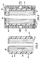
- FIGURE 9 shows the stack and termination components described and shown in FIGURE 8 contained within a battery enclosure 95 including (in this view) top and bottom walls 96 and 97 respectively, and left and right end walls 98 and 99 respectively.
- a battery enclosure 95 including (in this view) top and bottom walls 96 and 97 respectively, and left and right end walls 98 and 99 respectively.
- Any number of materials may be used for constructing the enclosure 95, such as those previously used in the battery art. These could take the form of flexible resin films or molded rigid plastics, the FIGURE showing a rigid polycarbonate honeycomb resin to result in a lighter weight but strong enclosure.
- An aperture 100 is found in end walls 98 and 99 in the illustrated embodiment to receive an intermodular connector, such as a piece of copper 103.
- an intermodular connector such as a piece of copper 103.
- other connector designs and locations could be employed depending on the end use of the finished batter. The arrangement and location of the connector would depend, inter alia , on whether the battery would be used by itself or whether it would be used in series or parallel connection with other encased batteries.
- Electrolyte addition and formation occurs prior to encasement and the addition of vents 94 by coupling an electrolyte fill tube to each of the fittings 89 (see FIGURE 8), preferably after the electrode stack and the electrolyte have been chilled to about -20°F.
- the stack 75 is put under compression between rigid end blocks, not shown (for example to compress the separator sheets in each cell by about 25%).
- Conductors are then attached to each of terminations 92 and 93, with formation taking place during repetitive filling and removal of the electrolyte using vacuum forming techniques which, in and of themselves, have been known to the art for some time. This procedure ensures charging of the battery to the desired potential, and removal of gases of formation.
- some electrolyte is removed so that substantially all remaining electrolyte is held within the separator sheets.
Landscapes
- Chemical & Material Sciences (AREA)
- Chemical Kinetics & Catalysis (AREA)
- Electrochemistry (AREA)
- General Chemical & Material Sciences (AREA)
- Engineering & Computer Science (AREA)
- Manufacturing & Machinery (AREA)
- Secondary Cells (AREA)
- Cell Electrode Carriers And Collectors (AREA)
Applications Claiming Priority (2)
| Application Number | Priority Date | Filing Date | Title |
|---|---|---|---|
| US821080 | 1992-01-16 | ||
| US07/821,080 US5225292A (en) | 1992-01-16 | 1992-01-16 | Internally folded expanded metal electrode for battery construction |
Publications (2)
| Publication Number | Publication Date |
|---|---|
| EP0552126A2 true EP0552126A2 (de) | 1993-07-21 |
| EP0552126A3 EP0552126A3 (en) | 1993-09-15 |
Family
ID=25232445
Family Applications (1)
| Application Number | Title | Priority Date | Filing Date |
|---|---|---|---|
| EP19930630002 Withdrawn EP0552126A3 (en) | 1992-01-16 | 1993-01-14 | Internally folded expanded metal electrode for battery construction |
Country Status (3)
| Country | Link |
|---|---|
| US (1) | US5225292A (de) |
| EP (1) | EP0552126A3 (de) |
| JP (1) | JPH05343071A (de) |
Cited By (2)
| Publication number | Priority date | Publication date | Assignee | Title |
|---|---|---|---|---|
| EP0650210A1 (de) * | 1993-10-12 | 1995-04-26 | Gnb Battery Technologies Inc. | Verfahren zur Montage von Bleibatterien |
| WO2006114605A1 (en) * | 2005-04-27 | 2006-11-02 | Atraverda Limited | Electrode and manufacturing methods |
Families Citing this family (10)
| Publication number | Priority date | Publication date | Assignee | Title |
|---|---|---|---|---|
| US5547036A (en) * | 1994-09-26 | 1996-08-20 | Chrysler Corporation | Battery support device |
| US5441824A (en) * | 1994-12-23 | 1995-08-15 | Aerovironment, Inc. | Quasi-bipolar battery requiring no casing |
| US5639568A (en) * | 1995-10-16 | 1997-06-17 | Aer Energy Resources, Inc. | Split anode for a dual air electrode cell |
| US5993494A (en) * | 1997-07-25 | 1999-11-30 | Gnb Technologies, Inc. | Method of manufacturing modular components for a bipolar battery and the resulting bipolar battery |
| DE102004003066B4 (de) * | 2004-01-21 | 2008-01-03 | Varta Automotive Systems Gmbh | Prismatischer Akkumulator und Verfahren zur Herstellung desselben |
| FR2920913B1 (fr) * | 2007-09-06 | 2009-11-13 | Pellenc Sa | Batterie constituee d'une pluralite de cellules positionnees et reliees entre elles, sans soudure. |
| DE102008036318A1 (de) * | 2008-07-29 | 2010-02-04 | Elringklinger Ag | Verfahren zur Herstellung einer Bipolarzelle und Bipolarzelle für eine bipolare Batterie |
| US20120223681A1 (en) * | 2011-03-04 | 2012-09-06 | Stone Bradley W | Electrodes, Batteries, Electrode Production Methods, and Battery Production Methods |
| KR102126371B1 (ko) * | 2017-09-11 | 2020-06-25 | 주식회사 유뱃 | 전기화학 소자 및 그 제조 방법 |
| CN110544552B (zh) * | 2018-05-29 | 2022-10-04 | 昇印光电(昆山)股份有限公司 | 一种导电膜 |
Family Cites Families (12)
| Publication number | Priority date | Publication date | Assignee | Title |
|---|---|---|---|---|
| DE178855C (de) * | ||||
| FR640781A (fr) * | 1927-09-12 | 1928-07-21 | Perfectionnements aux accumulateurs à formation naturelle | |
| US3723181A (en) * | 1970-12-21 | 1973-03-27 | Esb Inc | Duplex electrode construction using continuous electrically nonconductive carrier strip |
| US3819412A (en) * | 1972-02-07 | 1974-06-25 | Tyco Laboratories Inc | Plates for lead acid batteries |
| DE2407853A1 (de) * | 1974-02-19 | 1975-09-04 | Ruediger Scholz | Akkumulatoren |
| US4048397A (en) * | 1975-01-17 | 1977-09-13 | Maxs Ag | Method and apparatus for interconnecting stacked electrodes of batteries |
| US4353969A (en) * | 1979-09-27 | 1982-10-12 | California Institute Of Technology | Quasi-bipolar battery construction and method of fabricating |
| US4761352A (en) * | 1985-05-17 | 1988-08-02 | Eastman Kodak Company | Accordian folded electrode assembly |
| AU574580B2 (en) * | 1985-06-04 | 1988-07-07 | Sgl Technic Ltd. | Rechargeable secondary battery |
| US4900643A (en) * | 1988-04-08 | 1990-02-13 | Globe-Union Inc. | Lead acid bipolar battery plate and method of making the same |
| US4874681A (en) * | 1988-04-14 | 1989-10-17 | Rippel Wally E | Woven-grid sealed quasi-bipolar lead-acid battery construction and fabricating method |
| US5017446A (en) * | 1989-10-24 | 1991-05-21 | Globe-Union Inc. | Electrodes containing conductive metal oxides |
-
1992
- 1992-01-16 US US07/821,080 patent/US5225292A/en not_active Expired - Fee Related
-
1993
- 1993-01-14 EP EP19930630002 patent/EP0552126A3/en not_active Withdrawn
- 1993-01-14 JP JP5021802A patent/JPH05343071A/ja active Pending
Cited By (3)
| Publication number | Priority date | Publication date | Assignee | Title |
|---|---|---|---|---|
| EP0650210A1 (de) * | 1993-10-12 | 1995-04-26 | Gnb Battery Technologies Inc. | Verfahren zur Montage von Bleibatterien |
| WO2006114605A1 (en) * | 2005-04-27 | 2006-11-02 | Atraverda Limited | Electrode and manufacturing methods |
| US8119290B2 (en) | 2005-04-27 | 2012-02-21 | Atraverda Limited | Electrode and manufacturing methods |
Also Published As
| Publication number | Publication date |
|---|---|
| EP0552126A3 (en) | 1993-09-15 |
| US5225292A (en) | 1993-07-06 |
| JPH05343071A (ja) | 1993-12-24 |
Similar Documents
| Publication | Publication Date | Title |
|---|---|---|
| CN100359746C (zh) | 层积型锂二次电池及其制造方法 | |
| KR0136040B1 (ko) | 쌍극전기 축전지 및 그 조립방법 | |
| CN109980137B (zh) | 双极电池组件 | |
| US6440604B1 (en) | Cell | |
| US4049882A (en) | Battery assembly | |
| CA1039805A (en) | Flat alkaline cell construction and method for assembling the same | |
| JPH06349518A (ja) | バイポーラ鉛蓄電池の組立方法と得られたバイポーラ電池 | |
| US5225292A (en) | Internally folded expanded metal electrode for battery construction | |
| US10992005B2 (en) | Deep pouch cell and method of manufacturing same | |
| JPH09335U (ja) | バッテリ | |
| JPH07142084A (ja) | 鉛蓄電池の組立て方法 | |
| KR20170110053A (ko) | 비수 전해액 2차 전지 및 그 제조 방법 | |
| EP0655793A2 (de) | Elektrochemische Zelle mit hoher Zuverlässigkeit und Elektrodenanordnung hierfür | |
| WO2019121332A1 (en) | Pouch cell and method of manufacturing same | |
| JPH08329972A (ja) | 電 池 | |
| KR100515832B1 (ko) | 이차전지의 전극 조립체 | |
| US5156932A (en) | Simple optimized lead-acid battery | |
| KR100911004B1 (ko) | 전지부와 이를 채용한 리튬이차전지 | |
| JP2002231298A (ja) | 電池及びこれを用いた組電池 | |
| EP0352450A1 (de) | Mehrschichtiges Laminat und Aufbau von Separatoren für elektrochemische Zellen | |
| KR100858807B1 (ko) | 파우치형 케이스와, 이를 채용한 리튬이차전지 | |
| KR20220011030A (ko) | 이차 전지의 제조 방법 및 가압 패드 | |
| KR102715868B1 (ko) | 이차 전지의 제조 방법 | |
| KR20060033642A (ko) | 적층형 리튬이차전지의 전극탭 처리방법 | |
| JP2009110812A (ja) | 電池及びその製造方法 |
Legal Events
| Date | Code | Title | Description |
|---|---|---|---|
| PUAI | Public reference made under article 153(3) epc to a published international application that has entered the european phase |
Free format text: ORIGINAL CODE: 0009012 |
|
| AK | Designated contracting states |
Kind code of ref document: A2 Designated state(s): DE FR GB IT |
|
| PUAL | Search report despatched |
Free format text: ORIGINAL CODE: 0009013 |
|
| AK | Designated contracting states |
Kind code of ref document: A3 Designated state(s): DE FR GB IT |
|
| 17P | Request for examination filed |
Effective date: 19940307 |
|
| 17Q | First examination report despatched |
Effective date: 19951027 |
|
| STAA | Information on the status of an ep patent application or granted ep patent |
Free format text: STATUS: THE APPLICATION IS DEEMED TO BE WITHDRAWN |
|
| 18D | Application deemed to be withdrawn |
Effective date: 19960801 |