EP0552538A1 - Dissipation thermique par des ailettes à canaux étroits pour refroidissement de composants électroniques de haute puissance - Google Patents
Dissipation thermique par des ailettes à canaux étroits pour refroidissement de composants électroniques de haute puissance Download PDFInfo
- Publication number
- EP0552538A1 EP0552538A1 EP92310599A EP92310599A EP0552538A1 EP 0552538 A1 EP0552538 A1 EP 0552538A1 EP 92310599 A EP92310599 A EP 92310599A EP 92310599 A EP92310599 A EP 92310599A EP 0552538 A1 EP0552538 A1 EP 0552538A1
- Authority
- EP
- European Patent Office
- Prior art keywords
- heat sink
- predetermined
- heat
- ratio
- thickness
- Prior art date
- Legal status (The legal status is an assumption and is not a legal conclusion. Google has not performed a legal analysis and makes no representation as to the accuracy of the status listed.)
- Granted
Links
Images







Classifications
-
- F—MECHANICAL ENGINEERING; LIGHTING; HEATING; WEAPONS; BLASTING
- F28—HEAT EXCHANGE IN GENERAL
- F28F—DETAILS OF HEAT-EXCHANGE AND HEAT-TRANSFER APPARATUS, OF GENERAL APPLICATION
- F28F3/00—Plate-like or laminated elements; Assemblies of plate-like or laminated elements
- F28F3/02—Elements or assemblies thereof with means for increasing heat-transfer area, e.g. with fins, with recesses, with corrugations
-
- H—ELECTRICITY
- H10—SEMICONDUCTOR DEVICES; ELECTRIC SOLID-STATE DEVICES NOT OTHERWISE PROVIDED FOR
- H10W—GENERIC PACKAGES, INTERCONNECTIONS, CONNECTORS OR OTHER CONSTRUCTIONAL DETAILS OF DEVICES COVERED BY CLASS H10
- H10W40/00—Arrangements for thermal protection or thermal control
- H10W40/20—Arrangements for cooling
- H10W40/22—Arrangements for cooling characterised by their shape, e.g. having conical or cylindrical projections
-
- H—ELECTRICITY
- H10—SEMICONDUCTOR DEVICES; ELECTRIC SOLID-STATE DEVICES NOT OTHERWISE PROVIDED FOR
- H10W—GENERIC PACKAGES, INTERCONNECTIONS, CONNECTORS OR OTHER CONSTRUCTIONAL DETAILS OF DEVICES COVERED BY CLASS H10
- H10W40/00—Arrangements for thermal protection or thermal control
- H10W40/20—Arrangements for cooling
- H10W40/25—Arrangements for cooling characterised by their materials
- H10W40/253—Semiconductors
-
- H—ELECTRICITY
- H10—SEMICONDUCTOR DEVICES; ELECTRIC SOLID-STATE DEVICES NOT OTHERWISE PROVIDED FOR
- H10W—GENERIC PACKAGES, INTERCONNECTIONS, CONNECTORS OR OTHER CONSTRUCTIONAL DETAILS OF DEVICES COVERED BY CLASS H10
- H10W40/00—Arrangements for thermal protection or thermal control
- H10W40/20—Arrangements for cooling
- H10W40/25—Arrangements for cooling characterised by their materials
- H10W40/258—Metallic materials
-
- H—ELECTRICITY
- H10—SEMICONDUCTOR DEVICES; ELECTRIC SOLID-STATE DEVICES NOT OTHERWISE PROVIDED FOR
- H10W—GENERIC PACKAGES, INTERCONNECTIONS, CONNECTORS OR OTHER CONSTRUCTIONAL DETAILS OF DEVICES COVERED BY CLASS H10
- H10W40/00—Arrangements for thermal protection or thermal control
- H10W40/20—Arrangements for cooling
- H10W40/25—Arrangements for cooling characterised by their materials
- H10W40/259—Ceramics or glasses
-
- H—ELECTRICITY
- H10—SEMICONDUCTOR DEVICES; ELECTRIC SOLID-STATE DEVICES NOT OTHERWISE PROVIDED FOR
- H10W—GENERIC PACKAGES, INTERCONNECTIONS, CONNECTORS OR OTHER CONSTRUCTIONAL DETAILS OF DEVICES COVERED BY CLASS H10
- H10W40/00—Arrangements for thermal protection or thermal control
- H10W40/40—Arrangements for thermal protection or thermal control involving heat exchange by flowing fluids
- H10W40/43—Arrangements for thermal protection or thermal control involving heat exchange by flowing fluids by flowing gases, e.g. forced air cooling
Definitions
- This invention relates to the cooling of heat-producing electronic components. More particularly, this invention relates to heat sinks, coolant delivery systems, circuit layouts, and methods of optimizing the dimensions of heat sinks.
- Effectively dissipating the heat produced by the operation of electronic components is an important concern in optimizing the performance of the circuitry in which those components are used. In addition to optimizing performance, effective heat dissipation also helps to prolong the useful life of those components. Heat dissipation is particularly important in the case of high power electronic components which may produce three watts per square centimeter or more.
- Some exotic methods of cooling of high power electronic components such as forced liquid cooling of heat sinks attached to those components, have been proposed, but these methods are not desirable because they are costly to implement and maintain.
- Simple air cooling techniques have been avoided because of the inadequate performance of heat sinks and coolant delivery systems developed to date and because of a general perception that air cooling is not up to the task of adequately dissipating the heat produced by today's high power electronic components.
- Hilbert et al. "High Performance Micro Channel Air Cooling," Proceedings of the Sixth Annual IEEE SEMI-THERM Symposium, pp. 108-113, 1990, refers to an array of microchannel finned heat sinks in which air was specially ducted to the top of each heat sink.
- the heat sinks were said to have achieved thermal impedances in the range of 1.6 to 2.1 °C per watt.
- Both Goldberg and Hilbert do not deal with heat sinks having an optimum configuration which maximizes their heat dissipation capability.
- both Goldberg and Hilbert refer to unusually shaped heat sinks which are difficult and expensive to manufacture.
- Goldberg and Hilbert achieve the performance they achieve with coolant delivery systems which are non-standard in most electronic systems.
- Most electronic systems either push or pull air flow across electronic components which are situated on flat circuit boards which are disposed in a parallel configuration in bays or racks in a cabinet. There is a fan shelf placed at the top or bottom of the system to force air into the cabinet and through the spaces between the parallel circuit cards.
- the flow impingement techniques of Goldberg and Hilbert cannot be used with, or readily adapted to, these kinds of cooling arrangements.
- the need for adequate heat dissipation capabilities noted above is satisfied by a novel open channel heat sink which is dimensioned in a fashion which optimizes the heat dissipation capability of the heat sink.
- the heat sink comprises a plurality of fins, each having a predetermined thickness and a predetermined height.
- a plurality of channels each having a predetermined width are located between the fins of the heat sink.
- the heat dissipation capability of the heat sink can be optimized if fin thickness and channel width parameters are jointly and appropriately selected. For example, the heat dissipation capability of the heat sink is optimized if the ratio of the fin thickness to the fin height is about 0.005 to about 0.055 and the ratio of the channel width to the fin height is about 0.030 to about 0.130.
- a novel method of determining the optimum configuration of a heat sink so that heat generated by components connected to the heat sink is most effectively dissipated involves determining combinations of a fin thickness parameter and a channel width parameter which produce a desired thermal resistance.
- a relationship between a thermal resistance parameter and a combination of parameters relating to fin thickness and channel width is derived. Combinations of parameters relating to fin thickness and channel width are found which give a minimum value of the thermal resistance parameter.
- FIG. 1 shows an example of a narrow channel heat sink in accordance with this invention.
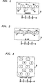
- FIG. 2 shows an example of a circuit pack in accordance with this invention having a staggered configuration of heat sinked electronic components.
- FIG. 3 shows an example of a circuit pack in accordance with this invention having an in-line configuration of heat sinked electronic components.
- FIG. 4 shows an example of a circuit pack in accordance with this invention having a plurality of rows of staggered heat sinked components.
- FIG. 5 shows a coolant delivery apparatus for cooling the circuit packs shown in any of FIGs. 2 through 4.
- FIG. 6 is a top view of a portion of the apparatus shown in FIG. 5 illustrating air entry slots and pressure taps in the top plate of an enclosure for the circuit pack.
- FIG. 7 shows pressure drop measurements with respect to ambient and with respect to channel input for a circuit pack with a staggered heat sinked component configuration.
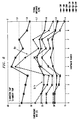
- FIGs. 8 and 9 illustrate temperature rises above ambient for each component in a circuit pack with a slotted cover plate for two different fan voltages.
- FIG. 10 is a comparison between the performances of circuit packs having a slotted cover plate and a solid cover plate.
- FIG. 11 is a comparison of the effect of circuit pack layout and air flow entry method on thermal impedance.
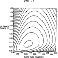
- FIGs. 12, 13, 14, and 15 are contour plots illustrating the optimization of heat sink dimensions at four different pressure drops across the heat sink.
- FIG. 16 shows an example of a heat sink in accordance with this invention into which an electronic heat producing component is integrated.
- FIG. 17 shows a heat sink in accordance with this invention which has been incorporated into the structure of a molded or encapsulated electronic heat producing component.
- FIG. 1 shows an example of an optimized heat sink 10 in accordance with this invention.
- the heat sink 10 comprises a row of fins 12, one of which explicitly bears the reference numeral 12 in FIG. 1.
- Each fin has a predetermined height H and a predetermined thickness ⁇ .
- the height H may be from about 0.25 cm. to about 3.2 cm.
- the fins project from a rectangularly shaped base 14 of the heat sink 10.
- the base 14 has a predetermined width W and a predetermined depth D.
- the width of the base 14 may be about 2.5 cm and the depth of the base 14 likewise may be about 2.5 cm.
- the overall height of the heat sink, from the bottom of the base 14 to the tips of the fins 12, may be about 3.8 cm. to about 7.6 cm.
- the base 14 of the heat sink 10 in the example of FIG. 1 is rectangular, the base may be any convenient shape such as circular, rectangular, or triangular.
- the fins 12 comprise rectangularly shaped protrusions standing substantially upright on the base 14.
- the fins 12 extend substantially from the front to the back of the heat sink and define a plurality of parallel rectangular channels or grooves of predetermined substantially constant width S between adjacent fins 12. As shown in FIG. 1, the channels are open at the top of the heat sink 10.
- the fins 12 have substantially rectangular cross-sections parallel and perpendicular to the longitudinal axes of the channels.
- the fin thickness ⁇ and the channel width S are selected so that the heat dissipation capabilities of the heat sink are optimized.
- the heat sink is attached to a heat producing electronic component in any heat conductive manner.
- the heat sink can be attached to such a component by means of a heat conductive adhesive, such as a heat conductive epoxy.
- the heat sink 10 in FIG. 1 may be made from any suitable heat conductive material such as aluminum, copper, or other metallic material. It may also be a semiconductor, a ceramic, a composite, or an alloy.
- the channels and fins may be formed in a rectangular block of such heat conductive material by any of a variety of methods. For example, the channels and the fins may be created by techniques such as crystal-orientation-dependent etching, precision sawing, electric discharge machining, or numerically controlled machining.
- a heat sink in accordance with this invention may take is a folded fin heat sink similar to those used in air conditioning and automotive radiators.
- the fabrication technique sued to make folded fin heat sinks can produce fin thickness and spacings in the range of interest at a relatively low cost.
- aluminum sheet in the desired thickness is folded over in a serpentine fashion so that a desired channel spacing is created.
- This folded fin may then be bonded to an aluminum base, for example, by dip brazing.
- the heat sink can then be attached to an electronic device in any manner which promotes conduction of heat from the device to the heat sink.
- the device may be attached via some heat conductive epoxy.
- the heat sink can also be attached to the electronic component by any other mechanical means which puts the device in intimate heat conductive contact with the heat sink.
- the folded fin construction has the advantage of connecting adjacent fin tips which makes the heat sink more resistant to damage from handling.
- One advantage of using such a folded fin heat sink is that it may be lanced, offset, or wavey to break up thermal boundary layers which may form in the cooling fluid flow.
- heat dissipation performance of a heat sink can be optimized by appropriately selecting a combination of fin thickness and channel width parameters.
- a heat sink such as the heat sink 10 of FIG. 1 or the folded fin heat sink described above.
- fin thickness and channel width parameters we have found that for a given pressure drop across the heat sink, there is an optimum range of fin thicknesses and an optimum range of spacings between the fins.
- the performance of such an optimized heat sink in terms of thermal resistance and heat dissipation capability is substantially improved as compared with prior heat sinks.
- the ratio of the predetermined fin thickness to predetermined fin height i.e., ⁇ /H
- the ratio of the predetermined channel width to the predetermined fin height i.e., S/H
- the actual ranges within which these ratios fall may be selected so as to optimize the heat dissipation capabilities of the heat sink for some specific fluid pressure drops expected to be found across the heat sink.
- the ratio of the fin thickness to the fin height may be from about 0.005 to 0.055 and the ratio of the channel width to fin height may be from about 0.08 to 0.13 for a pressure drop of about 0.05cm H2O.
- the ratio of the fin thickness to the fin height may be from about 0.005 to about 0.055 and the ratio of the channel width to fin height may be from about 0.060 to about 0.110 for a pressure drop of 0.15 cm. H2O.
- the ratio of the fin thickness to fin height may be from about 0.005 to 0.055 and the ratio of the channel width to the fin height may be from about 0.040 to about 0.090 for a pressure drop of 0.05 cm.
- the ratio of the fin thickness to the fin height may be from about 0.005 to 0.055 and the ratio of the channel width to fin height may be from about 0.03 to 0.08 for a pressure drop of 1.5cm H2O.
- the thermal impedances for the heat sinks of items a.)-d.) above were about 2.4 °C per watt, 1.54 °C per watt, 0.94 °C per watt, and 0.61 °C./watt, respectively.
- the dimensions of the base 14 of the heat sink comprise a width dimension of 2.5 cm. and a length dimension of 2.5 cm.
- the total height of the heat sink from the bottom of the base 14 to the tips of the fins 12 is about 2.0 cm.
- the height H of each fin 12 is about 1.25 cm.
- the thickness ⁇ of each fin 12 is about 0.4 mm
- the width S of each channel is about 1.1 mm.
- FIG. 2 shows an example of a layout of elements in a circuit pack in accordance with this invention.
- FIG. 2 shows schematically a circuit pack comprising six circuit elements 18, 20, 22, 24, 26, and 28, which are situated on a base plate 30 which, for example, may be made of a glass-epoxy material.
- the circuit pack as is more evident in FIGs. 5 and 6, is enclosed in a housing through which cooling fluid is drawn to cool the heat producing electronic components on the base plate 30 of the circuit pack.
- the housing and base plate 30 from a sort of wind tunnel which removes the heat produced by those electronic components.
- the circuit elements 18, 20, 22, 24, 26, and 28 may each comprise an electronic component attached to an aluminum heat sink having a 2.5 cm by 2.5 cm by 2.0 cm base 14with fins 12 which are 0.4 mm thick defining parallel channels which are 1.1 mm wide.
- the channels of the heat sinks are oriented generally parallel to the direction of fluid flow through the housing indicated by arrows 32.
- a transistor is one example of an electronic component which may be attached in any heat conductive manner to the base of the heat sink.
- the heat sinked components are arranged in a row extending perpendicularly with respect to the direction of air flow indicated by the arrows 32 in FIG. 2. Alternate ones of the heat sinked components are also staggered in a direction parallel to the direction of fluid flow.
- the minimum spacing between adjacent heat sinks may be about 0.254 cm.
- FIG. 3 shows an alternative component layout for a circuit pack in accordance with this invention.
- the circuit elements 18, 20, 22, 24, 26, and 28 are situated on base plate 30 in an in-line configuration comprising a number of heat sinked components arranged in a row extending perpendicularly with respect to the direction of air flow illustrated by the arrows 32.
- the channels of the heat sinks are arranged generally parallel to the direction of coolant flow indicated by arrows 32.
- the heat sinked components are not staggered as they are in FIG. 2.
- FIG. 4 is yet another component layout for a circuit pack.
- FIG. 4 shows an arrangement of heat sinked components, one of which has been given a reference numeral 34 in FIG. 4.
- the arrangement in FIG. 4 may be considered a combination of an in-line and staggered configuration of heat sinked components which are generally uniformly distributed on the base plate 30 in FIG. 4.
- each row comprises two heat sinked components located on a line perpendicular to the direction of coolant flow indicated by arrows 32.
- the components in each row are staggered with respect to the components in adjacent rows in a direction perpendicular to the direction of coolant flow. This is to ensure that each component is not located in the direct wakes of adjacent components created by flow of cooling fluid through the circuit pack housing. This arrangement has been found to improve the heat dissipation capabilities of the circuit pack.
- FIGs. 5 and 6 illustrate an apparatus for delivery of cooling air to the heat sinked components.
- FIG. 5 shows a structure 36 which comprises a rectangular housing for enclosing a number of heat sinked components mounted on a base plate 30 as shown in any one of FIGs. 2 to 4.
- the enclosure comprises the aforementioned base plate 30 shown in any of FIGs. 2 to 4, vertically disposed end plates 38 and 39, and a horizontally disposed cover plate 40.
- Two vertically disposed side plates are situated on the front and back of the FIG. 5 apparatus between the base plate 30 and the cover plate 40.
- the end plates 38 and 39, the cover plate 40, and the side plates may be made of a plastic material such as that sold under the LEXAN trademark.
- the base plate 30, end plates 38 and 39, cover plate 40, and the two side plates define a rectangular housing into which the heat sinked components are arranged as shown in any one of FIGs. 2 to 4.
- the vertical spacing between the cover plate 40 and the base plate 30 is such that a controlled amount of space is defined between the cover plate 40 and the tips of the heat sinks connected to the electronic components.
- the spacing between the cover plate and tips of the heat sinks may be from about zero to about 0.25 cm., for example.
- the spacing between the tips of the heat sinks and the cover plate 40 is made as small as possible.
- the cover plate 40 may be positioned so that there is no clearance between the tips of the heat sink fins and the cover plate 40.
- One end of the circuit pack and housing shown in FIG. 5 communicates with a fan 42 located in a flared structure attached to the end of that apparatus.
- Any mechanism which creates a flow of coolant through the circuit pack and housing may be used instead of the fan 42 and flared structure shown in FIG. 5
- the fan 42 draws cooling air into one or more inlet openings in the circuit pack housing, across the heat sinks, and out through one or more openings in the end plate 39 of the circuit pack housing.
- the outlet openings can be one or more appropriately sized circular openings in an end wall 39 of the housing adjacent the fan and opposing the end plate 38.
- Flow of cooling fluid through the apparatus of FIG. 5 between the cover plate 40 and the base plate 30 dissipates the heat generated by the operation of the electronic components attached to the heat sinks.
- the fan 42 exhausts air heated by contact with the heat sinks as indicated by the arrows 44 shown in FIG. 5.
- cooling air may be introduced through one or more inlet openings into the circuit pack housing of FIG. 5.
- One preferred way in which air is input to the apparatus of FIG. 5 is by the provision of a number of air entry slots 46 in the cover plate 40 as indicated in FIG. 6.
- the illustration of the cover plate 40 in FIG. 6 shows an arrangement of air entry slots 46 for the circuit pack layout shown in FIG. 4 which involves one air entry slot 46 superimposed over each of the heat sinked components 34 as shown in FIG. 4.
- FIG. 6 also shows a number of pressure taps in the cover plate 40 which can be used to make air pressure measurements in the circuit pack indicated in the test results described below.
- the fan 42 draws cooling air through each of the air entry slots 46.
- the cooling air impinges on the heat sinks directly below each slot 46 in a direction perpendicular to the plane of the base plate 30, and then is drawn in a horizontal direction parallel to the base plate 30 through the channels between the fins of the heat sinks.
- the cooling air then is exhausted as shown by the arrows 44 in FIG. 5.
- the sizes of the air entry slots 46 may be made different so that a uniform, balanced coolant flow is maintained throughout the circuit pack housing.
- the sizes of the slots may be made progressively smaller the farther downstream they are located.
- the two slots furthest upstream have length and width dimensions which are approximately the same as the width and depth dimensions of the heat sinks centered under those upstream slots 46, namely, about 2.5 cm. by 2.5 cm. in the example described above.
- the length dimensions of the slots 46 gradually decrease the further downstream they are located.
- the length dimension of the two slots furthest downstream may be only about 60% of the length dimension of the slots furthest upstream in this example of the invention, namely, 1.5 cm. in the example described above.
- An alternative method of delivering cooling air to a circuit pack involves the provision of a solid or unslotted top plate 40 and the removal of the end plate 38.
- cooling air is drawn through the opening in the end of the circuit pack housing, through the channels of the heat sinks in the circuit pack in a direction parallel to the base plate 30, and out the exhaust as indicated by arrows 44 in FIG. 5.
- An actual heat sink was constructed of a block of aluminum which was 2.5 cm. wide by 2.5 cm. long by 2.0 cm. high. Fins 0.4 mm thick were machined 1.1 mm apart in the top surface of the block of aluminum, as shown in FIG. 1.
- a transistor was used as the heat source and it was affixed to the heat sink in a 1.5 cm.2 groove in the base plate of the heat sink.
- a transistor was used as a heat source because it can produce high wattage and is moderately compact about (1 cm.2).
- a circuit pack made of glass-epoxy (27.5 cm. x 20 cm.) supported a number of these heat sinked components. The components were placed in the staggered and in-line arrangements of FIGs 2-4 to investigate the effect of circuit pack layout.
- the distance between the edges of adjacent heat sinks was about 0.127 cm. in FIGs. 2 and 3.
- the vertical separation between alternate rows of components in FIG. 4, for example, the vertical distance between components numbered 5 and 7 in FIG. 4, was about 6.35 cm.
- the vertical distance between adjacent rows of components in FIG. 4, for example, the vertical distance between the edges of the components numbered 5 and 6 in FIG. 4, was about 2 cm.
- the horizontal separation between the vertical rows of components in FIG. 4, for example, the horizontal separation between the edges of the components numbered 5 and 6 in FIG. 4, was about 1 cm.
- Air was introduced to the heat sinks through slots in the top plate or through the end wall of the circuit pack housing.
- An impingement configuration was achieved by creating slots, positioned exactly above the components, in the top plate of the circuit pack housing.
- a second method for air flow introduction was arranged by removing the end plate and replacing the top cover with a solid plate. The data reported here are for both slotted or solid covers.
- FIG. 6 shows a circuit pack, housing, and fan acting as a sort of wind tunnel for this experiment.
- the fan used for the experiment was a EG&G Rotron (Patriot-DC) fan.
- a top view of the cover plate is shown in FIG. 6 which shows the positions (A, B, C, D, and E) where air pressure was measured.
- the circuit pack was then placed inside what more resembles a conventional wind tunnel, which simulates a typical arrangement of electronic equipment in a frame or bay. In this case, clearance existed between the heat sink tips and the cover plate. This conventional wind tunnel arrangement was used to investigate the effect of flow bypass on thermal performance of the heat sink.
- FIG. 7 shows the pressure drops for three different fan voltages, 16, 32, and 48 volts. These pressure differences are reported with respect to ambient (positive values) and with respect to the inlet of the circuit pack housing (negative values).
- the thermal performance of the heat sink is reported in terms of the temperature rise over ambient ⁇ T and thermal impedance, ⁇ ja .
- the temperature rise used for calculation of thermal impedance is based on the temperature rise between the heat sink base plate and room ambient.
- FIGs 8 and 9 show the ⁇ T and ⁇ ja at different component power dissipations (13, 16, and 20W) at 16V and 48V fan voltages, respectively.
- the abscissa shows the component number on the circuit pack. (Those numbers are reproduced in FIGs. 2-4 in addition to the reference numerals already mentioned in the description above.) For this configuration, air is impinged on the component through the slotted cover plate described above.
- the device junction temperature is well below an industry standard of 125 °C for operation of the device in a worst case ambient temperature of 50 °C.
- FIG. 10 shows the impact of different coolant delivery systems on the dissipation of heat produced by the components and the performance of the heat sinks in the circuit pack.
- Two component power dissipations 13 and 16W are reported at a fan voltage of 32V for the slotted and solid cover plates. In the latter, the air flow is parallel to the circuit pack and there is no tip clearance between the heat sink and the cover plate.
- the figure shows that the air flow direction will impact the temperature rise. Specifically, improved performance is obtained when direct impingement through slots in the cover plate is used.
- the cooling achieved by introducing the flow parallel to the circuit pack through an end wall is still significant and certainly within acceptable design limits. Further, FIG.
- cooling is a function of component position on the circuit pack and similar levels of cooling can be attained with both types of flow introduction. This is demonstrated by components 5 and 6.
- exemplary thermal performance of a properly designed narrow channel heat sink in accordance with this invention may be achieved with either coolant delivery system.
- FIG. 11 further corroborates the conclusion stated above.
- FIG. 11 shows ⁇ ja for various flow introduction methods and component arrangements.
- FIG. 11 also contains data relating to a situation where there is clearance (represented by a curve labeled CONVENTIONAL wind tunnel in FIG. 11) between the tips of the heat sink fins and the cover plate of the circuit pack housing.
- the clearance was 1.25 cm (worst case) and the power dissipation per component was 16W.
- the data was taken at a fan voltage of 32V. To have the same air velocity in the circuit pack housing, the pressure drops were matched for the cases where there was tip clearance and where there was no tip clearance.
- the second point to note is component arrangement.
- the cover plate was solid and and there was no tip clearance.
- the results show that component arrangement does not impair performance as long as components are not placed in the direct wake of any of the other components, immediately down stream of one another, such that flow through the heat sink is blocked or otherwise impaired.
- Comparison of ⁇ ja for solid cover, staggered and in-line, in FIG. 11, further corroborates this point. Therefore, one can conclude that properly designed narrow channel heat sinks perform well regardless of component layout on a circuit pack, provided direct blockage is avoided.
- R air 1 2 ⁇ A f VC p
- ⁇ is the density of the cooling fluid, in this case air
- a f flow area of the heat sink
- V is the flow velocity
- C p is the specific heat of the coolant.
- a graphical method can be used involving the plotting of the total thermal impedance as a function of fin thickness parameter ⁇ /H and channel spacing parameter S/H in a contour plot using a software package called SURFER available from Golden Software, 807 14th Street, P.O. Box 281, Golden, Colorado 80402.
- FIG. 14 is a contour plot for a heat sink like that of FIGs. 12 and 13, but for a coolant flow rate which creates a pressure difference ⁇ P across the heat sink of .05 cm. H2O.
- FIG. 15 is a contour plot for a heat sink analogous to that of FIGs 12-14, but for a coolant flow rate which creates a pressure difference of 1.5cm. H2O. The plot of FIG.
- thermal impedance increases rapidly for fin thicknesses and channel spacings less than optimum, and more slowly for fin thicknesses and channel spacings greater than optimum. Due to production variations, it may thus be advantageous to design a heat sink with fin thickness and channel spacing slightly larger than optimum.
- FIG. 16 shows a heat sink in accordance with this invention which has been integrated with a heat producing electronic component.
- the heat sink of FIG. 16 is created by forming a number of rectangular parallel channels in a rectangular block of semiconductor material which is suitable for the fabrication of integrated circuits.
- the formation of the channels in the block of semiconductor material creates a series of fins 12 extending from a base 14 having a predetermined height and a predetermined width depending upon the depths of the channels and the distances separating the channels.
- the channels are formed so that the channel width and fin thickness dimensions are optimized as described above.
- An integrated circuit 48 is formed in the base 14 of the heat sink by any technique of creating integrated circuits such as photolithography.
- FIG. 17 shows a heat sink which has been incorporated into an encapsulated or molded heat producing electronic component 50 such as a hybrid integrated circuit.
- the component 50 comprises a substrate supporting one or more heat producing electronic components which may be integrated circuits or discrete components.
- the substrate also supports a heat sink 52 dimensioned in accordance with the design procedures of this invention.
- the heat sink is attached in heat conductive relationship with one or more heat producing electronic components.
- the component 50 also includes a molding or encapsulation material 54 which covers the components located on the substrate.
- a cavity 56 is formed in the encapsulation or molding material 54 which allows cooling fluid flow to be directed through the channels of the heat sink 52 in the component 50.
- the heat sink fins may extend outside the encapsulation material 54 and be cooled by coolant flow directed over the exterior of component 50.
- a narrow channel heat sink has been described and its thermal performance has been verified.
- the heat sink's performance is exemplary for a variety of flow directions.
- Tip clearance flow bypass
- Component layout on the circuit board does not significantly affect thermal performance of the heat sink as long as the flow of cooling fluid through the heat sinks is not blocked.
- Narrow channel heat sinks require only moderate pressure drops to achieve the improved performance reported here. This is readily attained with standard cooling fans.
- Narrow channel heat sinks can be readily used to cool high power electronic components. Components dissipating 20 W/cm2 (based on heat source area) or higher showed maximum temperature rises of only 38 °C for moderate forced air convection cooling.
Landscapes
- Engineering & Computer Science (AREA)
- Physics & Mathematics (AREA)
- Thermal Sciences (AREA)
- Mechanical Engineering (AREA)
- General Engineering & Computer Science (AREA)
- Cooling Or The Like Of Electrical Apparatus (AREA)
- Cooling Or The Like Of Semiconductors Or Solid State Devices (AREA)
Priority Applications (1)
| Application Number | Priority Date | Filing Date | Title |
|---|---|---|---|
| EP95112492A EP0683624A3 (fr) | 1991-12-16 | 1992-11-20 | Dissipateur thermique à ailettes à canaux étroits pour refroidir des composants électroniques de puissance |
Applications Claiming Priority (2)
| Application Number | Priority Date | Filing Date | Title |
|---|---|---|---|
| US80768791A | 1991-12-16 | 1991-12-16 | |
| US807687 | 1991-12-16 |
Related Child Applications (2)
| Application Number | Title | Priority Date | Filing Date |
|---|---|---|---|
| EP95112492.4 Division-Into | 1992-11-20 | ||
| EP95112492A Division EP0683624A3 (fr) | 1991-12-16 | 1992-11-20 | Dissipateur thermique à ailettes à canaux étroits pour refroidir des composants électroniques de puissance |
Publications (2)
| Publication Number | Publication Date |
|---|---|
| EP0552538A1 true EP0552538A1 (fr) | 1993-07-28 |
| EP0552538B1 EP0552538B1 (fr) | 1996-03-13 |
Family
ID=25196952
Family Applications (2)
| Application Number | Title | Priority Date | Filing Date |
|---|---|---|---|
| EP92310599A Revoked EP0552538B1 (fr) | 1991-12-16 | 1992-11-20 | Dissipation thermique par des ailettes à canaux étroits pour refroidissement de composants électroniques de haute puissance |
| EP95112492A Withdrawn EP0683624A3 (fr) | 1991-12-16 | 1992-11-20 | Dissipateur thermique à ailettes à canaux étroits pour refroidir des composants électroniques de puissance |
Family Applications After (1)
| Application Number | Title | Priority Date | Filing Date |
|---|---|---|---|
| EP95112492A Withdrawn EP0683624A3 (fr) | 1991-12-16 | 1992-11-20 | Dissipateur thermique à ailettes à canaux étroits pour refroidir des composants électroniques de puissance |
Country Status (4)
| Country | Link |
|---|---|
| US (1) | US5304846A (fr) |
| EP (2) | EP0552538B1 (fr) |
| KR (1) | KR930015999A (fr) |
| DE (1) | DE69209042T2 (fr) |
Cited By (4)
| Publication number | Priority date | Publication date | Assignee | Title |
|---|---|---|---|---|
| WO1998004108A1 (fr) * | 1996-07-22 | 1998-01-29 | Northrop Grumman Corporation | Refroidissement par microcanaux a l'aide de carburants d'aviation pour dispositifs electroniques d'avion |
| EP0903971A1 (fr) * | 1997-08-08 | 1999-03-24 | Itelco - S.p.A. | Distributeur d'agent réfrigérant avec les ailettes des réfroidissements réparti sélectives pour les composants électroniques |
| WO2014019941A1 (fr) * | 2012-08-01 | 2014-02-06 | Cooltech Applications | Piece monobloc comprenant un materiau magnetocalorique ne comprenant pas un alliage comprenant du fer et du silicium et un lanthanide, et generateur thermique comprenant ladite piece |
| WO2014019938A1 (fr) * | 2012-08-01 | 2014-02-06 | Cooltech Applications | Pièce monobloc comprenant un matériau magnétocalorique comprenant un alliage comprenant du fer et du silicium et au moins un lanthanide, et procédé de fabrication de ladite pièce monobloc |
Families Citing this family (70)
| Publication number | Priority date | Publication date | Assignee | Title |
|---|---|---|---|---|
| GB2276763B (en) * | 1993-03-30 | 1997-05-07 | Thermalloy Inc | Method and apparatus for dissipating thermal energy |
| CA2140311A1 (fr) * | 1994-01-14 | 1995-07-15 | Joseph P. Mennucci | Lamelle multicouche et son procede de fabrication |
| US5777259A (en) * | 1994-01-14 | 1998-07-07 | Brush Wellman Inc. | Heat exchanger assembly and method for making the same |
| JP3158983B2 (ja) * | 1994-10-03 | 2001-04-23 | 住友精密工業株式会社 | Lsiパッケージ冷却用コルゲート型放熱フィン |
| WO1996036205A1 (fr) * | 1995-05-11 | 1996-11-14 | International Electronic Research Corporation | Dissipateur de chaleur ameliore |
| US6022426A (en) * | 1995-05-31 | 2000-02-08 | Brush Wellman Inc. | Multilayer laminate process |
| US5709263A (en) * | 1995-10-19 | 1998-01-20 | Silicon Graphics, Inc. | High performance sinusoidal heat sink for heat removal from electronic equipment |
| US5957194A (en) * | 1996-06-27 | 1999-09-28 | Advanced Thermal Solutions, Inc. | Plate fin heat exchanger having fluid control means |
| US5932925A (en) * | 1996-09-09 | 1999-08-03 | Intricast, Inc. | Adjustable-pressure mount heatsink system |
| US6401807B1 (en) * | 1997-04-03 | 2002-06-11 | Silent Systems, Inc. | Folded fin heat sink and fan attachment |
| US6187412B1 (en) | 1997-06-27 | 2001-02-13 | International Business Machines Corporation | Silicon article having columns and method of making |
| US6213194B1 (en) | 1997-07-16 | 2001-04-10 | International Business Machines Corporation | Hybrid cooling system for electronics module |
| US5829514A (en) * | 1997-10-29 | 1998-11-03 | Eastman Kodak Company | Bonded cast, pin-finned heat sink and method of manufacture |
| US6705388B1 (en) | 1997-11-10 | 2004-03-16 | Parker-Hannifin Corporation | Non-electrically conductive thermal dissipator for electronic components |
| US5937517A (en) * | 1997-11-12 | 1999-08-17 | Eastman Kodak Company | Method of manufacturing bonded dual extruded, high fin density heat sinks |
| US6009938A (en) * | 1997-12-11 | 2000-01-04 | Eastman Kodak Company | Extruded, tiered high fin density heat sinks and method of manufacture |
| US6301779B1 (en) | 1998-10-29 | 2001-10-16 | Advanced Thermal Solutions, Inc. | Method for fabricating a heat sink having nested extended surfaces |
| US6308771B1 (en) | 1998-10-29 | 2001-10-30 | Advanced Thermal Solutions, Inc. | High performance fan tail heat exchanger |
| GB2347020B (en) | 1999-02-02 | 2003-05-14 | 3Com Technologies Ltd | Cooling equipment |
| US20010050161A1 (en) * | 1999-08-18 | 2001-12-13 | Gregory M. Chrysler | Folded fin heat sinks |
| JP2001110956A (ja) * | 1999-10-04 | 2001-04-20 | Matsushita Electric Ind Co Ltd | 電子部品用の冷却機器 |
| AUPQ332199A0 (en) * | 1999-10-07 | 1999-11-04 | Hydrocool Pty Limited | Heat exchanger for an electronic heat pump |
| US6619044B2 (en) | 1999-10-07 | 2003-09-16 | Hydrocool Pyt, Limited | Heat exchanger for an electronic heat pump |
| US6446442B1 (en) | 1999-10-07 | 2002-09-10 | Hydrocool Pty Limited | Heat exchanger for an electronic heat pump |
| US20040068991A1 (en) * | 1999-10-07 | 2004-04-15 | Ben Banney | Heat exchanger for an electronic heat pump |
| AU779519B2 (en) * | 1999-10-07 | 2005-01-27 | Hydrocool Pty Limited | A heat exchanger |
| GB2358243B (en) | 1999-11-24 | 2004-03-31 | 3Com Corp | Thermally conductive moulded heat sink |
| WO2002049106A1 (fr) * | 2000-12-11 | 2002-06-20 | Fujitsu Limited | Module électronique |
| WO2002052912A1 (fr) * | 2000-12-23 | 2002-07-04 | Korea Advanced Institute Of Science & Technology | Dissipateur thermique |
| US20040182542A1 (en) * | 2001-04-23 | 2004-09-23 | Koichiro Take | Heat sink |
| US6422307B1 (en) * | 2001-07-18 | 2002-07-23 | Delphi Technologies, Inc. | Ultra high fin density heat sink for electronics cooling |
| US7108055B2 (en) * | 2002-03-29 | 2006-09-19 | Advanced Energy Technology Inc. | Optimized heat sink using high thermal conducting base and low thermal conducting fins |
| US7269005B2 (en) * | 2003-11-21 | 2007-09-11 | Intel Corporation | Pumped loop cooling with remote heat exchanger and display cooling |
| US7203064B2 (en) * | 2003-12-12 | 2007-04-10 | Intel Corporation | Heat exchanger with cooling channels having varying geometry |
| US7017655B2 (en) | 2003-12-18 | 2006-03-28 | Modine Manufacturing Co. | Forced fluid heat sink |
| US20050141195A1 (en) * | 2003-12-31 | 2005-06-30 | Himanshu Pokharna | Folded fin microchannel heat exchanger |
| US20050257912A1 (en) * | 2004-01-12 | 2005-11-24 | Litelaser Llc | Laser cooling system and method |
| US7537151B2 (en) * | 2004-01-21 | 2009-05-26 | Delphi Technologies, Inc. | Method of making high performance heat sinks |
| US7147041B2 (en) * | 2004-05-03 | 2006-12-12 | Parker-Hannifin Corporation | Lightweight heat sink |
| US20050254208A1 (en) * | 2004-05-17 | 2005-11-17 | Belady Christian L | Air flow direction neutral heat transfer device |
| WO2006017301A2 (fr) * | 2004-07-13 | 2006-02-16 | Thorrn Micro Technologies, Inc. | Dissipateur de chaleur possedant des canaux microscopiques |
| DE102004040557A1 (de) * | 2004-08-16 | 2006-02-23 | Kern, Dietmar, Dr.-Ing. | Elektronikkühlkörper |
| US7077189B1 (en) | 2005-01-21 | 2006-07-18 | Delphi Technologies, Inc. | Liquid cooled thermosiphon with flexible coolant tubes |
| US7506682B2 (en) * | 2005-01-21 | 2009-03-24 | Delphi Technologies, Inc. | Liquid cooled thermosiphon for electronic components |
| US20060162903A1 (en) * | 2005-01-21 | 2006-07-27 | Bhatti Mohinder S | Liquid cooled thermosiphon with flexible partition |
| US7213636B2 (en) * | 2005-03-15 | 2007-05-08 | Delphi Technologies, Inc. | Cooling assembly with impingement cooled heat sink |
| US7073569B1 (en) | 2005-04-07 | 2006-07-11 | Delphi Technologies, Inc. | Cooling assembly with spirally wound fin |
| US7604040B2 (en) * | 2005-06-15 | 2009-10-20 | Coolit Systems Inc. | Integrated liquid cooled heat sink for electronic components |
| CN100543974C (zh) * | 2005-09-02 | 2009-09-23 | 富准精密工业(深圳)有限公司 | 散热模组及其制造方法 |
| US7143816B1 (en) | 2005-09-09 | 2006-12-05 | Delphi Technologies, Inc. | Heat sink for an electronic device |
| KR100772381B1 (ko) * | 2005-09-29 | 2007-11-01 | 삼성전자주식회사 | 히트싱크 |
| US7310953B2 (en) * | 2005-11-09 | 2007-12-25 | Emerson Climate Technologies, Inc. | Refrigeration system including thermoelectric module |
| US20070101737A1 (en) * | 2005-11-09 | 2007-05-10 | Masao Akei | Refrigeration system including thermoelectric heat recovery and actuation |
| US7597135B2 (en) * | 2006-05-23 | 2009-10-06 | Coolit Systems Inc. | Impingement cooled heat sink with low pressure drop |
| CN100518475C (zh) * | 2006-06-02 | 2009-07-22 | 富准精密工业(深圳)有限公司 | 散热装置 |
| US20080024997A1 (en) * | 2006-07-28 | 2008-01-31 | Apple Computer, Inc. | Staggered memory layout for improved cooling in reduced height enclosure |
| TW200814264A (en) * | 2006-09-07 | 2008-03-16 | Univ Nat Central | Heat sink structure for sub package substrate |
| US20080304230A1 (en) * | 2007-06-11 | 2008-12-11 | Franz John P | Heat-Sink Structure With Small Fin Gap Area |
| US20090173334A1 (en) * | 2007-11-08 | 2009-07-09 | Sunrgi | Composite material compositions, arrangements and methods having enhanced thermal conductivity behavior |
| US8812825B2 (en) | 2011-01-10 | 2014-08-19 | Dell Products L.P. | Methods and systems for managing performance and power utilization of a processor employing a fully multithreaded load threshold |
| US20120285667A1 (en) * | 2011-05-13 | 2012-11-15 | Lighting Science Group Corporation | Sound baffling cooling system for led thermal management and associated methods |
| US20150027662A1 (en) * | 2011-08-16 | 2015-01-29 | Antonius Henricus Hubertus Schmitz | Climate system |
| TWI566673B (zh) * | 2012-08-20 | 2017-01-11 | 鴻準精密工業股份有限公司 | 散熱器組合 |
| CN103151319A (zh) * | 2012-10-14 | 2013-06-12 | 中国计量学院 | 分形鳍片散热器 |
| CN104519713B (zh) * | 2013-09-29 | 2017-08-25 | 华为技术有限公司 | 散热装置 |
| JP6504832B2 (ja) | 2014-01-28 | 2019-04-24 | ゼネラル・エレクトリック・カンパニイ | 統合された取り付けおよび冷却の装置、電子装置、および車両 |
| US10073512B2 (en) | 2014-11-19 | 2018-09-11 | General Electric Company | System and method for full range control of dual active bridge |
| DE102019210192A1 (de) * | 2019-07-10 | 2020-08-20 | Siemens Aktiengesellschaft | Kühlung von elektrischen Bauelementen |
| CN115360153B (zh) * | 2022-08-24 | 2023-09-29 | 南京中电芯谷高频器件产业技术研究院有限公司 | 一种微波源制冷基板及其制备方法 |
| US12080627B1 (en) * | 2023-02-17 | 2024-09-03 | University Of Sharjah | Thermal management device for high heat flux applications including a microchannel heat sink assembly and method for manufacturing the same |
Citations (3)
| Publication number | Priority date | Publication date | Assignee | Title |
|---|---|---|---|---|
| DE2358443A1 (de) * | 1972-11-24 | 1974-06-06 | Sony Corp | Waermezerstreuungsvorrichtung |
| DE3528291A1 (de) * | 1985-08-07 | 1987-02-19 | Kernforschungsz Karlsruhe | Anordnung zur kuehlung elektronischer bauelemente |
| US4884630A (en) * | 1988-07-14 | 1989-12-05 | Microelectronics And Computer Technology Corporation | End fed liquid heat exchanger for an electronic component |
Family Cites Families (15)
| Publication number | Priority date | Publication date | Assignee | Title |
|---|---|---|---|---|
| US4103737A (en) * | 1976-12-16 | 1978-08-01 | Marantz Company, Inc. | Heat exchanger structure for electronic apparatus |
| US4620216A (en) * | 1983-04-29 | 1986-10-28 | International Business Machines Corporation | Unitary slotted heat sink for semiconductor packages |
| DE3573137D1 (en) * | 1984-10-03 | 1989-10-26 | Sumitomo Electric Industries | Material for a semiconductor device and process for its manufacture |
| US4823869A (en) * | 1986-06-19 | 1989-04-25 | International Business Machines Corporation | Heat sink |
| US4922378A (en) * | 1986-08-01 | 1990-05-01 | Texas Instruments Incorporated | Baseboard for orthogonal chip mount |
| US5031072A (en) * | 1986-08-01 | 1991-07-09 | Texas Instruments Incorporated | Baseboard for orthogonal chip mount |
| US4682651A (en) * | 1986-09-08 | 1987-07-28 | Burroughs Corporation (Now Unisys Corporation) | Segmented heat sink device |
| US4879891A (en) * | 1987-04-27 | 1989-11-14 | Thermalloy Incorporated | Method of manufacturing heat sink apparatus |
| US4884631A (en) * | 1988-03-17 | 1989-12-05 | California Institute Of Technology | Forced air heat sink apparatus |
| JP2507561B2 (ja) * | 1988-10-19 | 1996-06-12 | 株式会社日立製作所 | 半導体の冷却装置 |
| US4884168A (en) * | 1988-12-14 | 1989-11-28 | Cray Research, Inc. | Cooling plate with interboard connector apertures for circuit board assemblies |
| US5166775A (en) * | 1990-01-16 | 1992-11-24 | Cray Research, Inc. | Air manifold for cooling electronic devices |
| US4987478A (en) * | 1990-02-20 | 1991-01-22 | Unisys Corporation | Micro individual integrated circuit package |
| US5014117A (en) * | 1990-03-30 | 1991-05-07 | International Business Machines Corporation | High conduction flexible fin cooling module |
| US5003429A (en) * | 1990-07-09 | 1991-03-26 | International Business Machines Corporation | Electronic assembly with enhanced heat sinking |
-
1992
- 1992-11-20 EP EP92310599A patent/EP0552538B1/fr not_active Revoked
- 1992-11-20 EP EP95112492A patent/EP0683624A3/fr not_active Withdrawn
- 1992-11-20 DE DE69209042T patent/DE69209042T2/de not_active Revoked
- 1992-12-09 KR KR1019920023655A patent/KR930015999A/ko not_active Withdrawn
-
1993
- 1993-06-01 US US08/069,683 patent/US5304846A/en not_active Expired - Lifetime
Patent Citations (3)
| Publication number | Priority date | Publication date | Assignee | Title |
|---|---|---|---|---|
| DE2358443A1 (de) * | 1972-11-24 | 1974-06-06 | Sony Corp | Waermezerstreuungsvorrichtung |
| DE3528291A1 (de) * | 1985-08-07 | 1987-02-19 | Kernforschungsz Karlsruhe | Anordnung zur kuehlung elektronischer bauelemente |
| US4884630A (en) * | 1988-07-14 | 1989-12-05 | Microelectronics And Computer Technology Corporation | End fed liquid heat exchanger for an electronic component |
Non-Patent Citations (2)
| Title |
|---|
| IEEE TRANSACTIONS ON COMPONENTS, HYBRIDS AND MANUFACTURING TECHNOLOGY vol. CHMT7, no. 1, March 1984, pages 154 - 159 GOLDBERG 'Narrow Channel Forced Air Heat Sink' * |
| PROCEEDINGS OF THE SIXTH ANNUAL IEEE SEMI-THERM SYMPOSIUM 1990, pages 108 - 113 HILBERT 'High Performance Micro Channel Air Cooling' * |
Cited By (12)
| Publication number | Priority date | Publication date | Assignee | Title |
|---|---|---|---|---|
| WO1998004108A1 (fr) * | 1996-07-22 | 1998-01-29 | Northrop Grumman Corporation | Refroidissement par microcanaux a l'aide de carburants d'aviation pour dispositifs electroniques d'avion |
| EP0903971A1 (fr) * | 1997-08-08 | 1999-03-24 | Itelco - S.p.A. | Distributeur d'agent réfrigérant avec les ailettes des réfroidissements réparti sélectives pour les composants électroniques |
| US6457514B1 (en) | 1997-08-08 | 2002-10-01 | Itelco-S.P.A. | Liquid cooled dissipator for electronic components equipped with selectively arranged dissipation fins |
| WO2014019941A1 (fr) * | 2012-08-01 | 2014-02-06 | Cooltech Applications | Piece monobloc comprenant un materiau magnetocalorique ne comprenant pas un alliage comprenant du fer et du silicium et un lanthanide, et generateur thermique comprenant ladite piece |
| WO2014019938A1 (fr) * | 2012-08-01 | 2014-02-06 | Cooltech Applications | Pièce monobloc comprenant un matériau magnétocalorique comprenant un alliage comprenant du fer et du silicium et au moins un lanthanide, et procédé de fabrication de ladite pièce monobloc |
| FR2994253A1 (fr) * | 2012-08-01 | 2014-02-07 | Cooltech Applications | Piece monobloc comprenant un materiau magnetocalorique comprenant un alliage comprenant du fer et du silicium et au moins un lanthanide, et procede de fabrication de ladite piece monobloc |
| FR2994252A1 (fr) * | 2012-08-01 | 2014-02-07 | Cooltech Applications | Piece monobloc comprenant un materiau magnetocalorique ne comprenant pas un alliage comprenant du fer et du silicium et un lanthanide, et generateur thermique comprenant ladite piece |
| KR20150042219A (ko) * | 2012-08-01 | 2015-04-20 | 쿨테크 어플리케이션즈 에스.에이.에스. | 철, 규소 및 란타나이드를 포함하는 합금을 포함하지 않는 자기열량 재료를 포함한 일체형 부품, 및 상기 부품을 포함하는 열 제너레이터 |
| CN104662380A (zh) * | 2012-08-01 | 2015-05-27 | 制冷技术应用股份有限公司 | 包括不具有包含铁和硅和镧系元素的合金的磁致热材料的整体部件和包括所述部件的热发生器 |
| JP2015524908A (ja) * | 2012-08-01 | 2015-08-27 | クールテック・アプリケーションズ | 鉄、シリコン、ランタニドを含む合金を含まない磁気熱量材料を含む一体型部品、およびその部品を含む熱発生機 |
| US10101062B2 (en) | 2012-08-01 | 2018-10-16 | Cooltech Applications | One-piece part including a magnetocaloric material not including an alloy including iron and silicon and a lanthanide, and heat generator including said part |
| US10451319B2 (en) | 2012-08-01 | 2019-10-22 | Cooltech Applications | One-piece part including a magnetocaloric material including an alloy including iron and silicon and at least one lanthanide, and method for manufacturing said one-piece part |
Also Published As
| Publication number | Publication date |
|---|---|
| US5304846A (en) | 1994-04-19 |
| DE69209042D1 (de) | 1996-04-18 |
| DE69209042T2 (de) | 1996-10-02 |
| EP0552538B1 (fr) | 1996-03-13 |
| EP0683624A2 (fr) | 1995-11-22 |
| EP0683624A3 (fr) | 1995-12-06 |
| KR930015999A (ko) | 1993-07-24 |
Similar Documents
| Publication | Publication Date | Title |
|---|---|---|
| EP0552538B1 (fr) | Dissipation thermique par des ailettes à canaux étroits pour refroidissement de composants électroniques de haute puissance | |
| EP0551726B1 (fr) | Boîtier à dissipation de chaleur produit par des composants électroniques de haute puissance amélioré | |
| US5946190A (en) | Ducted high aspect ratio heatsink assembly | |
| Sathe et al. | A review of recent developments in some practical aspects of air-cooled electronic packages | |
| US3790859A (en) | Electronic package header system having omni-directional heat dissipation characteristic | |
| EP0410631B1 (fr) | Article comprenant un empilement de subassemblages électriques | |
| US5020586A (en) | Air-cooled heat exchanger for electronic circuit modules | |
| US4777560A (en) | Gas heat exchanger | |
| US6817405B2 (en) | Apparatus having forced fluid cooling and pin-fin heat sink | |
| Goldberg | Narrow channel forced air heat sink | |
| US5604665A (en) | Multiple parallel impingement flow cooling with tuning | |
| US5304845A (en) | Apparatus for an air impingement heat sink using secondary flow generators | |
| US6637505B1 (en) | Apparatus for cooling a box with heat generating elements received therein and a method for cooling same | |
| US5705854A (en) | Cooling apparatus for electronic device | |
| US20030062151A1 (en) | Heat sink and electronic circuit module including the same | |
| US6747873B1 (en) | Channeled heat dissipation device and a method of fabrication | |
| KR0136070B1 (ko) | 전자장치 | |
| Hilbert et al. | High performance air cooled heat sinks for integrated circuits | |
| JPH06213588A (ja) | 回路パックとそのヒートシンクの構造を最適化する方法 | |
| Shah et al. | A numerical study of the thermal performance of an impingement heat sink fin shape optimization | |
| EP0267772B1 (fr) | Echangeur de chaleur et son procédé de fabrication | |
| JP2002026214A (ja) | 電子部品冷却装置 | |
| JP3992953B2 (ja) | ヒートシンク | |
| Kondo et al. | Optimization of heat sink geometries for impingement air‐cooling of LSI packages | |
| JP3000846B2 (ja) | 電子部品用冷却装置 |
Legal Events
| Date | Code | Title | Description |
|---|---|---|---|
| PUAI | Public reference made under article 153(3) epc to a published international application that has entered the european phase |
Free format text: ORIGINAL CODE: 0009012 |
|
| AK | Designated contracting states |
Kind code of ref document: A1 Designated state(s): DE FR GB |
|
| 17P | Request for examination filed |
Effective date: 19940112 |
|
| 17Q | First examination report despatched |
Effective date: 19940505 |
|
| RAP3 | Party data changed (applicant data changed or rights of an application transferred) |
Owner name: AT&T CORP. |
|
| GRAA | (expected) grant |
Free format text: ORIGINAL CODE: 0009210 |
|
| AK | Designated contracting states |
Kind code of ref document: B1 Designated state(s): DE FR GB |
|
| XX | Miscellaneous (additional remarks) |
Free format text: TEILANMELDUNG 95112492.4 EINGEREICHT AM 09/08/95. |
|
| REF | Corresponds to: |
Ref document number: 69209042 Country of ref document: DE Date of ref document: 19960418 |
|
| ET | Fr: translation filed | ||
| PGFP | Annual fee paid to national office [announced via postgrant information from national office to epo] |
Ref country code: GB Payment date: 19960909 Year of fee payment: 5 |
|
| PLBQ | Unpublished change to opponent data |
Free format text: ORIGINAL CODE: EPIDOS OPPO |
|
| PLBI | Opposition filed |
Free format text: ORIGINAL CODE: 0009260 |
|
| PLBF | Reply of patent proprietor to notice(s) of opposition |
Free format text: ORIGINAL CODE: EPIDOS OBSO |
|
| 26 | Opposition filed |
Opponent name: ALUSUISSE TECHNOLOGY & MANAGEMENT AG Effective date: 19961213 |
|
| PLBF | Reply of patent proprietor to notice(s) of opposition |
Free format text: ORIGINAL CODE: EPIDOS OBSO |
|
| PGFP | Annual fee paid to national office [announced via postgrant information from national office to epo] |
Ref country code: FR Payment date: 19970917 Year of fee payment: 6 Ref country code: DE Payment date: 19970917 Year of fee payment: 6 |
|
| PG25 | Lapsed in a contracting state [announced via postgrant information from national office to epo] |
Ref country code: GB Free format text: LAPSE BECAUSE OF NON-PAYMENT OF DUE FEES Effective date: 19971120 |
|
| GBPC | Gb: european patent ceased through non-payment of renewal fee |
Effective date: 19971120 |
|
| RDAH | Patent revoked |
Free format text: ORIGINAL CODE: EPIDOS REVO |
|
| RDAG | Patent revoked |
Free format text: ORIGINAL CODE: 0009271 |
|
| 27W | Patent revoked |
Effective date: 19990212 |
|
| PLAB | Opposition data, opponent's data or that of the opponent's representative modified |
Free format text: ORIGINAL CODE: 0009299OPPO |