EP0552948A1 - Schutzteil für eine Flachdichtung - Google Patents
Schutzteil für eine Flachdichtung Download PDFInfo
- Publication number
- EP0552948A1 EP0552948A1 EP93300411A EP93300411A EP0552948A1 EP 0552948 A1 EP0552948 A1 EP 0552948A1 EP 93300411 A EP93300411 A EP 93300411A EP 93300411 A EP93300411 A EP 93300411A EP 0552948 A1 EP0552948 A1 EP 0552948A1
- Authority
- EP
- European Patent Office
- Prior art keywords
- gasket
- bolt
- spring member
- protecting
- engine
- Prior art date
- Legal status (The legal status is an assumption and is not a legal conclusion. Google has not performed a legal analysis and makes no representation as to the accuracy of the status listed.)
- Withdrawn
Links
Images

Classifications
-
- F—MECHANICAL ENGINEERING; LIGHTING; HEATING; WEAPONS; BLASTING
- F16—ENGINEERING ELEMENTS AND UNITS; GENERAL MEASURES FOR PRODUCING AND MAINTAINING EFFECTIVE FUNCTIONING OF MACHINES OR INSTALLATIONS; THERMAL INSULATION IN GENERAL
- F16J—PISTONS; CYLINDERS; SEALINGS
- F16J15/00—Sealings
-
- F—MECHANICAL ENGINEERING; LIGHTING; HEATING; WEAPONS; BLASTING
- F16—ENGINEERING ELEMENTS AND UNITS; GENERAL MEASURES FOR PRODUCING AND MAINTAINING EFFECTIVE FUNCTIONING OF MACHINES OR INSTALLATIONS; THERMAL INSULATION IN GENERAL
- F16J—PISTONS; CYLINDERS; SEALINGS
- F16J15/00—Sealings
- F16J15/02—Sealings between relatively-stationary surfaces
- F16J15/06—Sealings between relatively-stationary surfaces with solid packing compressed between sealing surfaces
- F16J15/08—Sealings between relatively-stationary surfaces with solid packing compressed between sealing surfaces with exclusively metal packing
- F16J15/0818—Flat gaskets
- F16J15/0825—Flat gaskets laminated
- F16J15/0831—Flat gaskets laminated with mounting aids
-
- F—MECHANICAL ENGINEERING; LIGHTING; HEATING; WEAPONS; BLASTING
- F16—ENGINEERING ELEMENTS AND UNITS; GENERAL MEASURES FOR PRODUCING AND MAINTAINING EFFECTIVE FUNCTIONING OF MACHINES OR INSTALLATIONS; THERMAL INSULATION IN GENERAL
- F16B—DEVICES FOR FASTENING OR SECURING CONSTRUCTIONAL ELEMENTS OR MACHINE PARTS TOGETHER, e.g. NAILS, BOLTS, CIRCLIPS, CLAMPS, CLIPS OR WEDGES; JOINTS OR JOINTING
- F16B5/00—Joining sheets or plates, e.g. panels, to one another or to strips or bars parallel to them
- F16B5/02—Joining sheets or plates, e.g. panels, to one another or to strips or bars parallel to them by means of fastening members using screw-thread
- F16B5/0241—Joining sheets or plates, e.g. panels, to one another or to strips or bars parallel to them by means of fastening members using screw-thread with the possibility for the connection to absorb deformation, e.g. thermal or vibrational
-
- F—MECHANICAL ENGINEERING; LIGHTING; HEATING; WEAPONS; BLASTING
- F16—ENGINEERING ELEMENTS AND UNITS; GENERAL MEASURES FOR PRODUCING AND MAINTAINING EFFECTIVE FUNCTIONING OF MACHINES OR INSTALLATIONS; THERMAL INSULATION IN GENERAL
- F16J—PISTONS; CYLINDERS; SEALINGS
- F16J15/00—Sealings
- F16J15/02—Sealings between relatively-stationary surfaces
- F16J15/06—Sealings between relatively-stationary surfaces with solid packing compressed between sealing surfaces
- F16J15/08—Sealings between relatively-stationary surfaces with solid packing compressed between sealing surfaces with exclusively metal packing
- F16J15/0818—Flat gaskets
- F16J2015/085—Flat gaskets without fold over
-
- F—MECHANICAL ENGINEERING; LIGHTING; HEATING; WEAPONS; BLASTING
- F16—ENGINEERING ELEMENTS AND UNITS; GENERAL MEASURES FOR PRODUCING AND MAINTAINING EFFECTIVE FUNCTIONING OF MACHINES OR INSTALLATIONS; THERMAL INSULATION IN GENERAL
- F16J—PISTONS; CYLINDERS; SEALINGS
- F16J15/00—Sealings
- F16J15/02—Sealings between relatively-stationary surfaces
- F16J15/06—Sealings between relatively-stationary surfaces with solid packing compressed between sealing surfaces
- F16J15/08—Sealings between relatively-stationary surfaces with solid packing compressed between sealing surfaces with exclusively metal packing
- F16J15/0818—Flat gaskets
- F16J2015/0868—Aspects not related to the edges of the gasket
Definitions
- the present invention relates to a protecting member for a gasket installed in an internal combustion engine, which can prevent creep relaxation of the gasket caused by repeated changes or alterations of forces applied to the gasket through bolts for connecting the engine parts.
- a gasket G is installed between the cylinder head CH and the cylinder block CB, and is securely held therebetween by bolts BO.
- the engine is actuated, when a fuel is combusted in a cylinder bore Hc, large force F is applied to the cylinder head CH, and when the combusted gas in the cylinder bore Hc is exhausted, the pressure applied to the cylinder head Hc Is released.
- the kind and degree of the creep relaxation of the gasket or bead depend on the quality of the material that the gasket is made. In case the gasket is formed of a spring steel plate, creep relaxation of the bead does not occur so easily. However, in case the changes of the pressure applied to the gasket are large, the spring ability or resiliency of the bead decreases gradually, and the bead does not function as installed at first to thereby cause leakage of fluid through the bead.
- one object of the invention is to provide a protecting member for a gasket, which can effectively prevent creep relaxation of the gasket.
- Another object of the invention is to provide a protecting member for a gasket as stated above, which can reduce changes of tension applied to bolts regardless of the condition of the engine.
- a further object of the invention is to provide a protecting member for a gasket as stated above, which can be formed as a part of the gasket.
- a still further object of the invention is to provide a protecting member for a gasket as stated above, which can be manufactured easily and economically.
- a protecting member for a gasket in accordance with the invention is designed to protect a gasket used for an internal combustion engine with two engine parts, especially a cylinder head gasket.
- the engine parts include bolt holes and are tightened by bolts.
- the protecting member is formed of a spring member situated between the two engine parts and located around the bolt. When the bolt is tightened, the spring member abuts against the engine parts and is compressed to provide predetermined pressure to the bolt through the engine parts.
- the cylinder head is made of an aluminum alloy
- thermal expansion and conductive rates are different from those of the bolts.
- the cylinder head becomes hot and expands at first, and then the bolts become hot.
- tightening pressure to the gasket becomes high, which exceeds the initial tightening pressure applied to the bolts BO.
- the tightening pressure decreases.
- the engine when the engine is actuated, the engine has a combustion cycle and an exhaust cycle.
- the combustion cycle the cylinder head is pushed outwardly to thereby reduce tightening pressure applied to the gasket.
- the exhaust cycle the tightening pressure against the gasket increases again.
- the spring member absorbs force applied to the gasket through the bolt.
- creep relaxation of the gasket is improved.
- the spring member protects creep relaxation of the sealing means. Also, in case the gasket has a coating, flow of the coating is reduced.
- the protecting member may further include at least one seat member situated between the spring member and the engine part.
- the seat member protects the engine part from the spring member.
- the engine part may have a concave or depression around the bolt hole to receive the spring member therein.
- the seat member may also be situated in the concave.
- the spring member may be in a form of a coil, a dish or a bead.
- the spring member may have a ring shape situated around the bolt hole.
- the dish spring or the bead may be combined with the gasket as one unit.
- the bead may be formed in one of plates for the gasket.
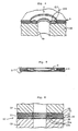
- FIG. 2 a first embodiment A of the protecting member of the invention is shown.
- An engine that the protecting member A is installed includes a cylinder head CH with a bolt hole Hb, and a cylinder block CB with a bolt hole Hb.
- a gasket G is situated between the cylinder head CH and the cylinder block CB.
- the cylinder block CB includes a depression A10 around the bolt hole Hb, in which the protecting member A is situated.
- the protecting member A is a coil spring A11 and is situated around a bolt BO. When the bolt BO is tightened, the cylinder head CH and the cylinder block CB are tightly connected together, and the coil spring A11 is strongly compressed.
- the moderate and constant pressure is generally applied to the gasket G regardless of the cycles of the engine.
- the cylinder head CH is made of an aluminum alloy and the blots BO are made of iron, thermal expansion and conductive rates are different from each other.
- the cylinder nead CH becomes hot and expands at first, and then the bolts BO become hot. Accordingly, after the cylinder head CH expands and before the bolts BO expand by heat, the tightening pressure to the gasket becomes high, which exceeds the initial tightening pressure applied to the bolts BO. Also, when the engine is stopped and is cooled, the tightening pressure decreases.
- the present invention absorbs the excess tightening pressure.
- a plurality of sealing means is formed around cylinder bores Hc and other holes, such as water holes and oil holes. If the surface pressure applied to the gasket changes repeatedly, creep relaxation occurs to the sealing means, however, in the present invention, surface pressure of the gasket G does not change so much. Thus, creep relaxation of the sealing means is effectively reduced.
- Fig 3 shows a second embodiment B of the protecting member of the invention.
- the cylinder head CH includes a depression B12, while the cylinder block CB includes a depression B10.
- a seat member B13 is situated in the depression B12, while a seat member B14 is situated in the depression B10.
- the seat members B13, B14 are made of hard materials.
- the cylinder head CH and the cylinder block CB are made of soft metals, such as an aluminum alloy
- the cylinder head CH and the cylinder block CB may be damaged by the spring B11.
- the seat members B13, B14 made of the hard materials are installed in the cylinder hard CH and the cylinder block CB. Accordingly, the cylinder head CH and the cylinder block CB are protected from the spring B11.
- the protecting member B operates as in the protecting member A.
- Fig. 4 shows a third embodiment C of the protecting member of the present invention.
- the protecting member C is formed of two curved ring plates C15, C16 with resiliency.
- the center portions orient outwardly, while the inner and outer edges of the plates C15, C16 abut against each other.
- the ring plates C15, C16 provide high spring forces when slightly compressed.
- the protecting member C is useful for providing strong tension to the bolt BO.
- the protecting member C operates as in the protecting member A.
- Fig. 5 shows a fourth embodiment D of the protecting member of the invention, wherein the protecting member D is combined with a gasket G1. In Fig 5, a compressed condition of the protecting member D is shown.
- the protecting member D has a ring shape with a bead, and is situated in a large hole of a gasket G1. Outer plates D17 are situated to cover the protecting member D. In this embodiment, the protecting member D is combined with and located inside the gasket Thus, it is easy to assemble the protecting member to the engine.
- Fig 6 shows an embodiment where protecting members are integrally formed with a gasket G2 and is compressed between the cylinder head CH and the cylinder block CB
- the gasket G2 is formed of seven plates 20-26, wherein the plate 22 includes a bead 22a, and the plate 24 includes a bead 24a.
- the beads 22a, 24a constitute the protecting members.
- the beads 22a, 24a extend beyond the outer surfaces of the plates 20, 26.
- the beads 22a, 24a are compressed to provide tension to the bolt through the cylinder head CH and the cylinder block CB.
- the beads 22a, 24a operate as the protecting members for the gasket.
- the protecting member provides to the bolt a pressure opposite to the tightening pressure of the bolt.
- the gasket is held between the cylinder head and the cylinder block by the tightening pressure and the counter force by the protecting member. Therefore, even if external force is applied to the cylinder head by combustion of the engine, such force is properly absorbed by the counter force of the protecting member. Consequently, the surface pressure applied to the gasket does not change so much. Thus, creep relaxation of the gasket, such as sealing means and coatings of the gasket, is reduced.
- the protecting member of the invention may be used for all the bolts.
- the protecting member may be partly used in the engine. Namely, when the cylinder head is fixed to the cylinder block, a center portion of the cylinder head may be slightly pushed upward by sealing means around the cylinder bores. In this case, if the protecting members are attached to the longitudinal ends of the cylinder heal, the longitudinal ends are not extremely compressed, so that the deformation of the cylinder head may be improved.
Landscapes
- Engineering & Computer Science (AREA)
- General Engineering & Computer Science (AREA)
- Mechanical Engineering (AREA)
- Gasket Seals (AREA)
Applications Claiming Priority (4)
| Application Number | Priority Date | Filing Date | Title |
|---|---|---|---|
| JP1992001809U JP2559886Y2 (ja) | 1992-01-22 | 1992-01-22 | 内燃機関用ガスケットの保護装置 |
| JP1992001805U JP2559885Y2 (ja) | 1992-01-22 | 1992-01-22 | 内燃機関用ガスケットの保護装置 |
| JP1805/92U | 1992-01-22 | ||
| JP1809/92U | 1992-01-22 |
Publications (1)
| Publication Number | Publication Date |
|---|---|
| EP0552948A1 true EP0552948A1 (de) | 1993-07-28 |
Family
ID=26335089
Family Applications (1)
| Application Number | Title | Priority Date | Filing Date |
|---|---|---|---|
| EP93300411A Withdrawn EP0552948A1 (de) | 1992-01-22 | 1993-01-21 | Schutzteil für eine Flachdichtung |
Country Status (3)
| Country | Link |
|---|---|
| US (1) | US5375856A (de) |
| EP (1) | EP0552948A1 (de) |
| KR (1) | KR930016694A (de) |
Cited By (2)
| Publication number | Priority date | Publication date | Assignee | Title |
|---|---|---|---|---|
| GB2273136A (en) * | 1992-12-04 | 1994-06-08 | Caterpillar Inc | Gasket assembly for sealed joints experiencing thermally induced movement |
| DE102004040516A1 (de) * | 2004-08-20 | 2006-02-23 | Reinz-Dichtungs-Gmbh | Metallische Flachdichtung mit verkürzter Dichtungslage |
Families Citing this family (9)
| Publication number | Priority date | Publication date | Assignee | Title |
|---|---|---|---|---|
| US5516120A (en) * | 1994-03-10 | 1996-05-14 | Dana Corporation | Two layer combustion flange |
| JP2000240797A (ja) * | 1999-02-24 | 2000-09-05 | Nichias Corp | メタルガスケット |
| JP2001271935A (ja) * | 2000-03-24 | 2001-10-05 | Nippon Gasket Co Ltd | ガスケットの締付け構造 |
| DE10258319A1 (de) * | 2002-12-13 | 2004-07-15 | Elringklinger Ag | Flachdichtung, insbesondere Abgaskrümmerdichtung, sowie eine solche Dichtung aufnehmende Baugruppe |
| DE10337677A1 (de) * | 2003-08-16 | 2005-03-17 | Federal-Mogul Sealing Systems Gmbh | Metallische Flachdichtung |
| US20060131817A1 (en) * | 2004-12-17 | 2006-06-22 | Kerelchuk Colin J | Gasket assembly for joints experiencing thermally induced movement |
| US20080304906A1 (en) * | 2007-06-11 | 2008-12-11 | Michael Henry Maj | Creep and Corrosion Mitigating Inserts for Bolted Joints |
| US20080309025A1 (en) * | 2007-06-15 | 2008-12-18 | Freudenberg-Nok General Partnership | Hybrid mounting providing sealing and nvh function for structures |
| WO2009152814A1 (de) * | 2008-06-21 | 2009-12-23 | Federal-Mogul Sealing Systems Gmbh | Flachdichtung |
Citations (3)
| Publication number | Priority date | Publication date | Assignee | Title |
|---|---|---|---|---|
| EP0338537A2 (de) * | 1988-04-21 | 1989-10-25 | Fel-Pro Incorporated | Aus mehreren Schichten bestehende einheitliche Abdichtung und Verfahren zu deren Herstellung |
| DE3842351A1 (de) * | 1988-12-16 | 1990-06-28 | Netter Gmbh | Verfahren und befestigung zum verbinden vibrierender gegenstaende |
| EP0440247A1 (de) * | 1990-02-01 | 1991-08-07 | Ishikawa Gasket Co. Ltd. | Metallabdichtung mit Abdichtelementen mit verschiedenen Federkonstanten |
Family Cites Families (7)
| Publication number | Priority date | Publication date | Assignee | Title |
|---|---|---|---|---|
| US1851948A (en) * | 1927-03-31 | 1932-03-29 | Frigidaire Corp | Gasket |
| FR84960E (fr) * | 1962-05-30 | 1965-05-21 | Joint d'étanchéité | |
| US4348032A (en) * | 1981-03-19 | 1982-09-07 | The Fluorocarbon Company | Head gasket having resilient seal with Belleville springs |
| JPS59121259A (ja) * | 1982-12-27 | 1984-07-13 | Yuusan Gasket Kk | 密封方法 |
| US4971338A (en) * | 1988-05-16 | 1990-11-20 | Ishikawa Gasket Co., Ltd. | Steel laminate gasket with associated beads |
| US5054793A (en) * | 1988-10-11 | 1991-10-08 | Brunswick Corporation | Resilient gasket with spacers |
| JP2521155Y2 (ja) * | 1990-08-07 | 1996-12-25 | 石川ガスケット 株式会社 | 断熱性金属積層形ガスケット |
-
1993
- 1993-01-19 US US08/005,359 patent/US5375856A/en not_active Expired - Fee Related
- 1993-01-20 KR KR1019930000668A patent/KR930016694A/ko not_active Abandoned
- 1993-01-21 EP EP93300411A patent/EP0552948A1/de not_active Withdrawn
Patent Citations (3)
| Publication number | Priority date | Publication date | Assignee | Title |
|---|---|---|---|---|
| EP0338537A2 (de) * | 1988-04-21 | 1989-10-25 | Fel-Pro Incorporated | Aus mehreren Schichten bestehende einheitliche Abdichtung und Verfahren zu deren Herstellung |
| DE3842351A1 (de) * | 1988-12-16 | 1990-06-28 | Netter Gmbh | Verfahren und befestigung zum verbinden vibrierender gegenstaende |
| EP0440247A1 (de) * | 1990-02-01 | 1991-08-07 | Ishikawa Gasket Co. Ltd. | Metallabdichtung mit Abdichtelementen mit verschiedenen Federkonstanten |
Cited By (3)
| Publication number | Priority date | Publication date | Assignee | Title |
|---|---|---|---|---|
| GB2273136A (en) * | 1992-12-04 | 1994-06-08 | Caterpillar Inc | Gasket assembly for sealed joints experiencing thermally induced movement |
| GB2273136B (en) * | 1992-12-04 | 1995-08-30 | Caterpillar Inc | Gasket assembly for sealed joints experiencing thermally induced movement |
| DE102004040516A1 (de) * | 2004-08-20 | 2006-02-23 | Reinz-Dichtungs-Gmbh | Metallische Flachdichtung mit verkürzter Dichtungslage |
Also Published As
| Publication number | Publication date |
|---|---|
| US5375856A (en) | 1994-12-27 |
| KR930016694A (ko) | 1993-08-26 |
Similar Documents
| Publication | Publication Date | Title |
|---|---|---|
| EP0306766B1 (de) | Laminierte Metalldichtung | |
| US6575473B2 (en) | Metallic gasket | |
| US5700017A (en) | Flanged rubber combustion seal | |
| JP3738121B2 (ja) | 金属製ガスケット | |
| US6036195A (en) | Metal gasket with double beads | |
| US6089573A (en) | Metal gasket with corrugated bead | |
| JPH086805B2 (ja) | 金属ガスケット | |
| JP2989282B2 (ja) | 金属ガスケット | |
| US5375856A (en) | Protecting member for a gasket | |
| US5873577A (en) | Metal laminate gasket with partial bead section | |
| EP1180620B1 (de) | Zylinderkopfdichtung mit partieller Dichtbeschichtung | |
| EP0494801B1 (de) | Brennkraftmaschine und metallische Abdichtung zur Anwendung in solcher Maschine | |
| US6164662A (en) | Metal gasket | |
| US5536024A (en) | Metal gasket having sealing beads with different width and height | |
| US5131668A (en) | Steel laminate gasket with seal protecting member | |
| US5439234A (en) | Metal gasket with edge support beads | |
| US5711537A (en) | Metal gasket with a bead surrounding bolt and oil holes | |
| US6168166B1 (en) | Metal gasket with two half beads | |
| EP1363751B1 (de) | Metallische flachdichtung mit kalt geformtem saum | |
| US6318733B1 (en) | Metal laminate gasket with elastic auxiliary sealing member | |
| US6161842A (en) | Metal gasket with different surface pressure portions | |
| US5199723A (en) | Steel laminate gasket with seal protecting member | |
| US5879012A (en) | Metal gasket with reduced thickness bead | |
| US5482298A (en) | Metal laminate type cylinder head gasket having grommets with different thicknesses | |
| EP0717218A1 (de) | Metallflachdichtung mit einem Ring |
Legal Events
| Date | Code | Title | Description |
|---|---|---|---|
| PUAI | Public reference made under article 153(3) epc to a published international application that has entered the european phase |
Free format text: ORIGINAL CODE: 0009012 |
|
| AK | Designated contracting states |
Kind code of ref document: A1 Designated state(s): DE ES FR GB IT SE |
|
| 17P | Request for examination filed |
Effective date: 19940118 |
|
| 17Q | First examination report despatched |
Effective date: 19950322 |
|
| GRAG | Despatch of communication of intention to grant |
Free format text: ORIGINAL CODE: EPIDOS AGRA |
|
| GRAG | Despatch of communication of intention to grant |
Free format text: ORIGINAL CODE: EPIDOS AGRA |
|
| GRAH | Despatch of communication of intention to grant a patent |
Free format text: ORIGINAL CODE: EPIDOS IGRA |
|
| 18W | Application withdrawn |
Withdrawal date: 19990318 |