EP0552991A2 - Procédé et dispositif de détection de défaillances du stator dans des machines dynamo-électriques tournantes - Google Patents
Procédé et dispositif de détection de défaillances du stator dans des machines dynamo-électriques tournantes Download PDFInfo
- Publication number
- EP0552991A2 EP0552991A2 EP93300513A EP93300513A EP0552991A2 EP 0552991 A2 EP0552991 A2 EP 0552991A2 EP 93300513 A EP93300513 A EP 93300513A EP 93300513 A EP93300513 A EP 93300513A EP 0552991 A2 EP0552991 A2 EP 0552991A2
- Authority
- EP
- European Patent Office
- Prior art keywords
- stator
- fault
- flux
- occurrence
- detected
- Prior art date
- Legal status (The legal status is an assumption and is not a legal conclusion. Google has not performed a legal analysis and makes no representation as to the accuracy of the status listed.)
- Granted
Links
Images


Classifications
-
- G—PHYSICS
- G01—MEASURING; TESTING
- G01R—MEASURING ELECTRIC VARIABLES; MEASURING MAGNETIC VARIABLES
- G01R31/00—Arrangements for testing electric properties; Arrangements for locating electric faults; Arrangements for electrical testing characterised by what is being tested not provided for elsewhere
- G01R31/34—Testing dynamo-electric machines
- G01R31/343—Testing dynamo-electric machines in operation
Definitions
- This invention relates to a method of detecting and locating stator faults in dynamoelectric machines during operation thereof, and to an apparatus for implementing the method.
- the invention is concerned with the detection and location of a shorted turn of the stator winding by monitoring the axial leakage flux.
- stator insulation breakdown is one of the major causes of failure. Additionally there is evidence that the majority of stator winding failures in such machines result from turn insulation breakdown. In some cases where there has been minimal or no core damage due to the fault, it is possible to isolate the damaged coil from the rest of the winding and restart the machine. Such an operation may necessitate isolation of other coils in order to retain balanced operation of the machine. In this way the machine can be returned to service quickly, albeit with degraded performance until a more complete repair or winding replacement can be scheduled. Unfortunately location of the failed coil is difficult and time consuming.
- An aim of the present invention is to provide a method of, and a device for, detecting the occurrence of a shorted turn and indicating its location in the stator winding of the machine while the machine is still running.
- the device of the present invention takes advantage of the existence of axial leakage flux in practical rotating machines.
- axial leakage flux does not exist since the currents flowing in rotor and stator circuits are equal but opposite in direction.
- asymmetries in the winding due to imperfections in construction and materials will result in a small imbalance between the rotor and stator currents. This imbalance will give rise to small but measurable axial flux harmonics which can be detected by a suitable sensor such as a coil placed concentric with the drive shaft of the machine.
- the method of the present invention can be summarized as follows, calculate, for a given winding, all time harmonics present during normal operation; refer these harmonics to the stator frame of reference since the sensing coil is static; derive the additional harmonics due to the occurrence of a shorted turn in the stator winding; and look for changes in these components to indicate the presence of an inter-turn fault.
- the location method relies on the disruption of the end winding magnetic field symmetry due to the fault.
- This field asymmetry can be detected by a system of coils axisymmetrically displaced about the drive shaft.
- the magnitude of the magnetic field sensed by each of these coils can be related, using the Biot-Savart law, to the angular displacement of the fault position from the coil.
- the location of the fault can be derived using a triangulation technique. In this case only the rms value of the coil emf is required; there is no requirement to measure the harmonic components.
- the present invention provides a method of detecting and locating stator faults in a dynamoelectric machine by monitoring changes in axial leakage flux during operation of the machine.
- the method comprises: identifying the frequencies of selected harmonic components of axial leakage flux that are to be significantly affected by the occurrence of a stator fault, detecting the axial leakage flux at each of a plurality of positions, including a datum position, distributed symmetrically around the axis of the rotor adjacent to an end winding of the stator, deriving from the detected flux at each of said positions a first signal having a value corresponding to the magnitude of the detected flux, storing the values of said first signals derived prior to the occurrence of a stator fault, deriving from the detected axial leakage flux a further signal having a value corresponding to the magnitude of said selected harmonic components, monitoring said further signal and detecting a change therein thereby detecting the occurrence of a stator fault, storing the values of said first signals derived after the occurrence of the stator
- stator fault representing a shorted turn is thus detected by monitoring selected axial flux harmonics which are sensitive to the occurrence.
- the angular position of the fault is computed from stored values, namely machine parameters which are initially known and measured values of the flux after detection of the fault.
- B s B1cos( ⁇ t-p ⁇ )+B5cos( ⁇ t+5p ⁇ )-B7cos( ⁇ t-7p ⁇ ) +B11cos( ⁇ t+11p ⁇ ) where B n are the spatial harmonic fluxes.
- Equation (7) gives the frequency components of the currents that are induced in the rotor due to the air gap space harmonics of a balanced winding and supply. In addition to these harmonics, the fundamental of the supply frequency will also appear in the axial flux spectrum. The presence of additional, higher order, harmonics can be accounted for by using the term n ⁇ rather than ⁇ .
- the corresponding waveform would have a mark-space ratio of 1:(2p-1) causing every 2p th harmonic to be absent.
- n ⁇ term in the argument of (10) causes the components defined above to beat at the slip frequency of the rotor current.
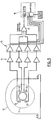
- the technique relies upon the use of an array of at least four search coils, or other appropriate sensors, distributed axisymmetrically about the drive shaft of the motor. These coils provide a local measure of the magnetic field in the end region of the machine. By triangulating the outputs from the search coils, it is possible to determine the location of the stator coil containing the interturn short circuit. In order to accomplish this function it is necessary to develop an expression for the field at any point on the circumference of the circle passing through the centres of the search coils due to the current flowing in the end winding of an arbitrarily positioned turn of the stator winding.
- Figure 3 illustrates the general case in which the shorted turn is displaced an angular amount ⁇ , from an arbitrary datum position.
- R2 is the mean radius of the end winding
- R1 is the radius of the circle on which the field is to be calculated.
- the circles are assumed to be coplanar and concentric.
- the length of arc of the coil is L and the field measurement point is displaced an angle ⁇ from the datum.
- r2 R12+R22-2R1R2cos( ⁇ + ⁇ )
- coils 1 and 2 form one pair
- coils 3 and 4 form the other pair.
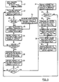
- the induced emf value on each of the coils is measured and recorded.
- the emf values on each of the coils are again recorded. These latter values are subtracted from the initial values and the modulus of the resultant is taken. Subsequently, the four positive numbers thus derived, i.e. B1, B2, B3 and B4, are input into the fault location algorithm.
Landscapes
- Physics & Mathematics (AREA)
- General Physics & Mathematics (AREA)
- Tests Of Circuit Breakers, Generators, And Electric Motors (AREA)
- Motor Or Generator Cooling System (AREA)
Applications Claiming Priority (2)
| Application Number | Priority Date | Filing Date | Title |
|---|---|---|---|
| US07/824,392 US5252915A (en) | 1992-01-23 | 1992-01-23 | Method and apparatus for detecting stator faults in rotary dynamoelectric machines |
| US824392 | 1992-01-23 |
Publications (3)
| Publication Number | Publication Date |
|---|---|
| EP0552991A2 true EP0552991A2 (fr) | 1993-07-28 |
| EP0552991A3 EP0552991A3 (fr) | 1994-04-13 |
| EP0552991B1 EP0552991B1 (fr) | 1999-11-24 |
Family
ID=25241287
Family Applications (1)
| Application Number | Title | Priority Date | Filing Date |
|---|---|---|---|
| EP93300513A Expired - Lifetime EP0552991B1 (fr) | 1992-01-23 | 1993-01-25 | Procédé et dispositif de détection de défaillances du stator dans des machines dynamo-électriques tournantes |
Country Status (5)
| Country | Link |
|---|---|
| US (1) | US5252915A (fr) |
| EP (1) | EP0552991B1 (fr) |
| AT (1) | ATE186988T1 (fr) |
| CA (1) | CA2086641C (fr) |
| DE (1) | DE69327066T2 (fr) |
Cited By (15)
| Publication number | Priority date | Publication date | Assignee | Title |
|---|---|---|---|---|
| DE19623808A1 (de) * | 1996-06-14 | 1997-12-18 | Siemens Ag | Vorrichtung und Verfahren zur Messung von charakteristischen Zustandsgrößen des Erregersystems der Läuferwicklung einer elektrodynamischen Maschine |
| EP1637896A3 (fr) * | 2002-09-26 | 2006-04-12 | Siemens Aktiengesellschaft | Diagnostic d'une machine électrique par surveillance du flux magnétique de la machine par une couche sensible au flux |
| DE19780321B4 (de) * | 1996-04-01 | 2006-10-19 | General Electric Co. | Selbstabstimmender und kompensierender Detektor für Wicklungsfehler |
| RU2319160C2 (ru) * | 2005-09-27 | 2008-03-10 | Академический институт прикладной энергетики | Способ контроля магнитного состояния статора погружного асинхронного электродвигателя (пэд) |
| GB2458780A (en) * | 2008-03-31 | 2009-10-07 | Gen Electric | Non-invasive monitoring and diagnosis of electric machines by measuring external flux density |
| WO2009127562A3 (fr) * | 2008-04-15 | 2009-12-10 | Alstom Technology Ltd | Procédé pour surveiller une machine électrodynamique |
| WO2012140455A3 (fr) * | 2011-04-11 | 2013-04-25 | University Of Zagreb | Commande tolérantes aux pannes à générateur pour éolienne à pas variable et à vitesse variable |
| WO2015124855A1 (fr) * | 2014-02-24 | 2015-08-27 | Lohr Electromecanique | Procédé de détection d'un court-circuit dans une machine synchrone équipée d'un capteur de position angulaire |
| CN106199424A (zh) * | 2016-06-29 | 2016-12-07 | 湖南工业大学 | 一种永磁同步电机匝间短路故障诊断方法 |
| EP3168631A1 (fr) * | 2015-11-13 | 2017-05-17 | ABB Technology Ltd. | Procédé et système pour déterminer l'état d'une machine électrique |
| CN108279362A (zh) * | 2017-12-15 | 2018-07-13 | 上海电力学院 | 海上双馈电机转子绕组匝间短路故障辨识方法 |
| EP3413066A1 (fr) * | 2017-06-07 | 2018-12-12 | Siemens Aktiengesellschaft | Détection de défaillances dans les enroulements d'une machine électrique |
| US10261130B2 (en) | 2014-02-24 | 2019-04-16 | Lohr Electromecanique | Method for measuring the ageing of permanent magnets of a synchronous machine fitted with an angular position sensor |
| US10312774B2 (en) | 2014-02-24 | 2019-06-04 | Lohr Electromecanique | Synchronous machine provided with an angular position sensor |
| WO2021025612A1 (fr) * | 2019-08-05 | 2021-02-11 | Sembcorp Industries Ltd | Procédé et système de détection de défaut d'enroulement lors du fonctionnement en ligne d'une machine électrique |
Families Citing this family (49)
| Publication number | Priority date | Publication date | Assignee | Title |
|---|---|---|---|---|
| US5461329A (en) * | 1992-01-21 | 1995-10-24 | Martin Marietta Energy Systems, Inc. | Method and apparatus for generating motor current spectra to enhance motor system fault detection |
| US5530343A (en) * | 1994-10-07 | 1996-06-25 | Computational Systems, Inc. | Induction motor speed determination by flux spectral analysis |
| US5680025A (en) * | 1994-10-07 | 1997-10-21 | Csi Technology, Inc. | Proactive motor monitoring for avoiding premature failures and for fault recognition |
| US5744723A (en) * | 1996-05-10 | 1998-04-28 | Csi Technology, Inc. | Method for determining rotational speed from machine vibration data |
| US5739698A (en) * | 1996-06-20 | 1998-04-14 | Csi Technology, Inc. | Machine fault detection using slot pass frequency flux measurements |
| US5907244A (en) * | 1996-08-02 | 1999-05-25 | Automation Technology, Inc. | Method and apparatus for detecting winding errors in an electric motor stator |
| US6064172A (en) * | 1997-02-11 | 2000-05-16 | Power Superconductor Applications Corporation | Method and apparatus for detection, classification and reduction of internal electrical faults in alternating current propulsion machinery using synchronous detection scheme |
| US6043664A (en) | 1997-06-06 | 2000-03-28 | General Electric Company | Method and apparatus for turn fault detection in multi-phase AC motors |
| US6184690B1 (en) | 1999-01-11 | 2001-02-06 | Fisher Data Products, Inc. | Pole to pole surge test for wound products |
| US6172509B1 (en) | 1999-02-11 | 2001-01-09 | The United States Of America As Represented By The Secretary Of The Air Force | Detecting polyphase machine faults via current deviation |
| US6791351B2 (en) * | 2002-06-28 | 2004-09-14 | Siemens Westinghouse Power Corporation | Electromagnetic stator insulation flaw detector |
| US6876222B2 (en) * | 2002-11-12 | 2005-04-05 | Siemens Westinghouse Power Corporation | Automated stator insulation flaw inspection tool and method of operation |
| DE10300051A1 (de) * | 2002-12-13 | 2004-07-15 | Daimlerchrysler Ag | Verfahren und Vorrichtung zum Testen von Elektromotoren insbesondere Lüftermotoren auf Funktionsfähigkeit |
| US7079039B2 (en) | 2002-12-13 | 2006-07-18 | Daimlerchrysler Ag | Process and device for testing electric motors, in particular fan motors, for functionality |
| US6911838B2 (en) * | 2003-03-31 | 2005-06-28 | General Electric Company | Online detection of shorted turns in a generator field winding |
| US6956459B2 (en) * | 2003-10-23 | 2005-10-18 | Siemens Westinghouse Power Corporation | Sensing apparatus for blown fuse of rectifying wheel and associated methods |
| US7081760B2 (en) * | 2004-07-12 | 2006-07-25 | Behrooz Mirafzal | Method of diagnosing a broken bar fault in an induction motor |
| RU2279103C2 (ru) * | 2004-07-15 | 2006-06-27 | Андрей Леонидович Назолин | Способ обнаружения дефектов узлов крепления статора на работающей электрической машине |
| US7239149B2 (en) * | 2005-08-19 | 2007-07-03 | Siemens Power Generation, Inc. | Search coil mount for facilitating inspection of a generator rotor in situ |
| US7253634B1 (en) | 2006-03-31 | 2007-08-07 | General Electric Company | Generator protection methods and systems self-tuning to a plurality of characteristics of a machine |
| US7592772B2 (en) * | 2007-10-08 | 2009-09-22 | University Of Victoria Innovation And Development Corporation | Stator inter-turn fault detection of synchronous machines |
| JP5238596B2 (ja) * | 2009-04-27 | 2013-07-17 | 株式会社日本自動車部品総合研究所 | 回転電機の放電量測定装置および放電量測定方法 |
| US8803461B2 (en) * | 2010-12-22 | 2014-08-12 | Arvind Kumar Tiwari | System and method for synchronous machine health monitoring |
| US8781765B2 (en) | 2011-04-11 | 2014-07-15 | General Electric Company | Online monitoring system and method to identify shorted turns in a field winding of a rotor |
| US20130033215A1 (en) * | 2011-08-01 | 2013-02-07 | Illinois Institute Of Technology | Apparatus and method for permanent magnet electric machine condition monitoring |
| US8179028B1 (en) | 2011-08-08 | 2012-05-15 | Rao Dantam K | Prevention of core failures in large electric machines |
| US8829769B1 (en) | 2012-11-09 | 2014-09-09 | Dantam K. Rao | Coated keybar to protect electric machines |
| US9018881B2 (en) * | 2013-01-10 | 2015-04-28 | GM Global Technology Operations LLC | Stator winding diagnostic systems and methods |
| EP2942633A1 (fr) * | 2014-05-06 | 2015-11-11 | Siemens Aktiengesellschaft | Procédé et dispositif de détection de court-circuit entre spires et machine électrique |
| US10288688B2 (en) * | 2014-07-24 | 2019-05-14 | Schweitzer Engineering Laboratories, Inc. | Systems and methods for monitoring and protecting an electric power generator |
| DE102016201127A1 (de) | 2016-01-27 | 2017-07-27 | Robert Bosch Gmbh | Verfahren zum Erkennen eines Fehlers in einer Generatoreinheit |
| DE102017101944A1 (de) * | 2017-02-01 | 2018-08-02 | Wobben Properties Gmbh | Verfahren zur Fehlerbestimmung an einem Generator und Generatorprüfsystem |
| US10514428B2 (en) * | 2017-07-13 | 2019-12-24 | Itt Manufacturing Enterprises Llc | Technique to detect motor leakage flux anomalies |
| US10931097B2 (en) | 2017-09-25 | 2021-02-23 | Schweitzer Engineering Laboratories, Inc. | Generator stator ground protection using third harmonic |
| US10333291B2 (en) | 2017-09-25 | 2019-06-25 | Schweitzer Engineering Laboratories, Inc. | Multiple generator ground fault detection |
| EP3499710A1 (fr) * | 2017-12-15 | 2019-06-19 | Siemens Aktiengesellschaft | Procédé de surveillance du fonctionnement d'une machine tournante électrique |
| US10928455B2 (en) | 2018-04-20 | 2021-02-23 | University Of Connecticut | System and methods for fault diagnosis in machines |
| US10797632B2 (en) | 2018-08-21 | 2020-10-06 | Schweitzer Engineering Laboratories, Inc. | Sensitive directional element for generator protection |
| WO2020128685A1 (fr) * | 2018-12-21 | 2020-06-25 | Abb Schweiz Ag | Dispositif de surveillance d'état et procédé de surveillance d'une machine électrique |
| PL429485A1 (pl) * | 2019-04-01 | 2019-09-23 | Politechnika Świętokrzyska | Zestaw do wykrywania zwarć i odłączania zasilania maszyn elektrycznych prądu przemiennego |
| US11316455B2 (en) | 2019-08-28 | 2022-04-26 | Schweitzer Engineering Laboratories, Inc. | Generator rotor turn-to-turn fault detection using fractional harmonics |
| US10819261B1 (en) | 2019-10-25 | 2020-10-27 | Schweitzer Engineering Laboratories, Inc. | Security improvements for electric power generator protection |
| CN112014776B (zh) * | 2020-09-11 | 2023-06-27 | 广东美的暖通设备有限公司 | 接线检测方法、磁悬浮压缩机、空调机组和可读存储介质 |
| US11631972B2 (en) | 2020-12-16 | 2023-04-18 | Schweitzer Engineering Laboratories, Inc. | Accurate modeling of equipment overexcitation damage curves |
| CN113359030A (zh) * | 2021-06-09 | 2021-09-07 | 西安热工研究院有限公司 | 基于外部漏磁检测的风力发电机短路故障模拟平台 |
| US12249948B2 (en) | 2022-08-30 | 2025-03-11 | Schweitzer Engineering Laboratories, Inc. | Split-phase protection of generators |
| CN115856626B (zh) * | 2023-02-03 | 2025-11-11 | 清华大学 | 多对极永磁同步电机转子局部失磁的故障磁极定位方法 |
| US11946966B1 (en) | 2023-02-20 | 2024-04-02 | Schweitzer Engineering Laboratories, Inc. | Selective stator ground fault protection using positive-sequence voltage reference |
| WO2025170949A1 (fr) * | 2024-02-05 | 2025-08-14 | Siemens Healthcare Diagnostics Inc. | Procédés de détection de position de structures magnétiques dans des moteurs à courant continu sans balais et dispositifs associés |
Family Cites Families (10)
| Publication number | Priority date | Publication date | Assignee | Title |
|---|---|---|---|---|
| SU661430A1 (ru) * | 1975-12-09 | 1979-05-05 | Предприятие П/Я А-7922 | Устройство дл обнаружени витковых замыканий в обмотках с параллельными ветв ми статоров трехфазных электрических машин |
| US4145653A (en) * | 1976-09-16 | 1979-03-20 | Kohler Co. | Waveform analyzer for rotating electrical circuitry |
| US4136312A (en) * | 1976-12-30 | 1979-01-23 | Westinghouse Electric Corp. | Method and apparatus for detection of rotor faults in dynamoelectric machines |
| US4230961A (en) * | 1978-09-12 | 1980-10-28 | Westinghouse Electric Corp. | Magnetic flux sensor for laminated cores |
| JPS5683223A (en) * | 1979-12-12 | 1981-07-07 | Hitachi Ltd | Rotary electric machine rotor winding malfunction detector |
| GB8428199D0 (en) * | 1984-11-08 | 1984-12-19 | Adwel Ltd | Motor monitor signal analysis system |
| JPH0687642B2 (ja) * | 1986-12-15 | 1994-11-02 | 株式会社日立製作所 | 回転電機の回転子巻線異常診断装置 |
| US4808932A (en) * | 1987-05-15 | 1989-02-28 | Electric Power Research Institute, Inc. | Rotor fault and location detector for induction motors |
| US4761703A (en) * | 1987-08-31 | 1988-08-02 | Electric Power Research Institute, Inc. | Rotor fault detector for induction motors |
| FI883335A7 (fi) * | 1988-01-14 | 1989-07-15 | Siemens Ag | Foerfarande och anordning foer bestaemmande av rotorresistensen hos en vridfaeltmaskin. |
-
1992
- 1992-01-23 US US07/824,392 patent/US5252915A/en not_active Expired - Lifetime
-
1993
- 1993-01-04 CA CA002086641A patent/CA2086641C/fr not_active Expired - Fee Related
- 1993-01-25 DE DE69327066T patent/DE69327066T2/de not_active Expired - Fee Related
- 1993-01-25 AT AT93300513T patent/ATE186988T1/de active
- 1993-01-25 EP EP93300513A patent/EP0552991B1/fr not_active Expired - Lifetime
Cited By (26)
| Publication number | Priority date | Publication date | Assignee | Title |
|---|---|---|---|---|
| DE19780321B4 (de) * | 1996-04-01 | 2006-10-19 | General Electric Co. | Selbstabstimmender und kompensierender Detektor für Wicklungsfehler |
| DE19623808A1 (de) * | 1996-06-14 | 1997-12-18 | Siemens Ag | Vorrichtung und Verfahren zur Messung von charakteristischen Zustandsgrößen des Erregersystems der Läuferwicklung einer elektrodynamischen Maschine |
| EP1637896A3 (fr) * | 2002-09-26 | 2006-04-12 | Siemens Aktiengesellschaft | Diagnostic d'une machine électrique par surveillance du flux magnétique de la machine par une couche sensible au flux |
| US7503219B2 (en) | 2002-09-26 | 2009-03-17 | Siemens Aktiengesellschaft | Monitoring and diagnosing a technical installation using purely mechanically activated signaling means |
| RU2319160C2 (ru) * | 2005-09-27 | 2008-03-10 | Академический институт прикладной энергетики | Способ контроля магнитного состояния статора погружного асинхронного электродвигателя (пэд) |
| GB2458780A (en) * | 2008-03-31 | 2009-10-07 | Gen Electric | Non-invasive monitoring and diagnosis of electric machines by measuring external flux density |
| GB2458780B (en) * | 2008-03-31 | 2012-05-23 | Gen Electric | Non-invasive monitoring and diagnosis of electric machines by measuring external flux density |
| WO2009127562A3 (fr) * | 2008-04-15 | 2009-12-10 | Alstom Technology Ltd | Procédé pour surveiller une machine électrodynamique |
| WO2012140455A3 (fr) * | 2011-04-11 | 2013-04-25 | University Of Zagreb | Commande tolérantes aux pannes à générateur pour éolienne à pas variable et à vitesse variable |
| CN106258001A (zh) * | 2014-02-24 | 2016-12-28 | 罗尔机电公司 | 用于检测配备有角位置传感器的同步机中的短路的方法 |
| US10261130B2 (en) | 2014-02-24 | 2019-04-16 | Lohr Electromecanique | Method for measuring the ageing of permanent magnets of a synchronous machine fitted with an angular position sensor |
| CN106258001B (zh) * | 2014-02-24 | 2019-06-14 | 罗尔机电公司 | 用于检测配备有角位置传感器的同步机中的短路的方法 |
| WO2015124855A1 (fr) * | 2014-02-24 | 2015-08-27 | Lohr Electromecanique | Procédé de détection d'un court-circuit dans une machine synchrone équipée d'un capteur de position angulaire |
| US10312774B2 (en) | 2014-02-24 | 2019-06-04 | Lohr Electromecanique | Synchronous machine provided with an angular position sensor |
| FR3017959A1 (fr) * | 2014-02-24 | 2015-08-28 | Lohr Electromecanique | Procede de detection d'un court-circuit dans une machine synchrone equipee d'un capteur de position angulaire |
| US9906185B2 (en) | 2014-02-24 | 2018-02-27 | Lohr Electromecanique | Method for detecting a short circuit in a synchronous machine fitted with an angular position sensor |
| CN106706028A (zh) * | 2015-11-13 | 2017-05-24 | Abb技术有限公司 | 用于检测电机状态的方法和系统 |
| EP3168631A1 (fr) * | 2015-11-13 | 2017-05-17 | ABB Technology Ltd. | Procédé et système pour déterminer l'état d'une machine électrique |
| CN106706028B (zh) * | 2015-11-13 | 2021-03-02 | Abb技术有限公司 | 用于检测电机状态的方法和系统 |
| CN106199424A (zh) * | 2016-06-29 | 2016-12-07 | 湖南工业大学 | 一种永磁同步电机匝间短路故障诊断方法 |
| EP3413066A1 (fr) * | 2017-06-07 | 2018-12-12 | Siemens Aktiengesellschaft | Détection de défaillances dans les enroulements d'une machine électrique |
| CN108279362A (zh) * | 2017-12-15 | 2018-07-13 | 上海电力学院 | 海上双馈电机转子绕组匝间短路故障辨识方法 |
| CN108279362B (zh) * | 2017-12-15 | 2020-04-10 | 上海电力学院 | 海上双馈电机转子绕组匝间短路故障辨识方法 |
| WO2021025612A1 (fr) * | 2019-08-05 | 2021-02-11 | Sembcorp Industries Ltd | Procédé et système de détection de défaut d'enroulement lors du fonctionnement en ligne d'une machine électrique |
| CN113439217A (zh) * | 2019-08-05 | 2021-09-24 | 胜科工业有限公司 | 在电气机器的在线运行下检测绕组故障的方法和系统 |
| US11500037B2 (en) | 2019-08-05 | 2022-11-15 | Sembcorp Industries Ltd | Method and a system of detecting winding fault under online operation of an electrical machine |
Also Published As
| Publication number | Publication date |
|---|---|
| US5252915A (en) | 1993-10-12 |
| ATE186988T1 (de) | 1999-12-15 |
| CA2086641A1 (fr) | 1993-07-24 |
| EP0552991B1 (fr) | 1999-11-24 |
| DE69327066T2 (de) | 2000-06-08 |
| DE69327066D1 (de) | 1999-12-30 |
| CA2086641C (fr) | 1997-11-04 |
| EP0552991A3 (fr) | 1994-04-13 |
Similar Documents
| Publication | Publication Date | Title |
|---|---|---|
| US5252915A (en) | Method and apparatus for detecting stator faults in rotary dynamoelectric machines | |
| US4518917A (en) | Plural sensor apparatus for monitoring turbine blading with undesired component elimination | |
| Kliman et al. | Sensorless, online motor diagnostics | |
| US4644270A (en) | Apparatus for monitoring housed turbine blading to obtain blading-to-housing distance | |
| CN104823064B (zh) | 用于检测电动机器中的故障状态的方法 | |
| US8095324B2 (en) | Permanent magnet rotor crack detection | |
| Kumar et al. | Stator end-winding thermal and magnetic sensor arrays for online stator inter-turn fault detection | |
| EP2541217B1 (fr) | Procédé d'identification d'une panne d'une machine électrique | |
| US6903556B2 (en) | Method and apparatus for testing laminated cores of electrical machines | |
| CN100449323C (zh) | 发电机励磁绕组的速度敏感绕组接地的检测方法 | |
| JPH0264206A (ja) | タービン羽根の振動をモニターする方法及び装置 | |
| US11579197B2 (en) | System and method for induction motor rotor bar surface magnetic field analysis | |
| US20160216333A1 (en) | System and method for induction motor rotor bar magnetic field analysis | |
| Sottile et al. | Experimental investigation of on-line methods for incipient fault detection [in induction motors] | |
| Xu et al. | Online detecting magnet defect fault in PMSG with magnetic sensing | |
| JP2839528B2 (ja) | 界磁巻線層間短絡位置検出装置 | |
| US5031459A (en) | Turbine generator shaft torsion monitor | |
| Ogidi et al. | Measuring fault indicators in electric machines-learning experience | |
| Ployard et al. | Detection of rotor faults in salient pole generator using flux density monitoring | |
| Schoen | On-line current-based condition monitoring of three-phase induction machines | |
| RU2090882C1 (ru) | Вихретоковый дефектоскоп для контроля цилиндрических изделий | |
| Penman et al. | A new approach to the protection of industrial drives | |
| JPH1062274A (ja) | 従動トルクの測定方法と測定装置 | |
| JP2003148996A (ja) | 測定装置、温度測定装置および回転電機の温度測定方法 | |
| Ramírez-Niño et al. | A mathematical method for improving the detecting of interturn short circuits in rotor windings of power generators |
Legal Events
| Date | Code | Title | Description |
|---|---|---|---|
| PUAI | Public reference made under article 153(3) epc to a published international application that has entered the european phase |
Free format text: ORIGINAL CODE: 0009012 |
|
| AK | Designated contracting states |
Kind code of ref document: A2 Designated state(s): AT BE CH DE DK ES FR GB GR IE IT LI LU MC NL PT SE |
|
| PUAL | Search report despatched |
Free format text: ORIGINAL CODE: 0009013 |
|
| AK | Designated contracting states |
Kind code of ref document: A3 Designated state(s): AT BE CH DE DK ES FR GB GR IE IT LI LU MC NL PT SE |
|
| 17P | Request for examination filed |
Effective date: 19940927 |
|
| 17Q | First examination report despatched |
Effective date: 19970312 |
|
| GRAG | Despatch of communication of intention to grant |
Free format text: ORIGINAL CODE: EPIDOS AGRA |
|
| GRAG | Despatch of communication of intention to grant |
Free format text: ORIGINAL CODE: EPIDOS AGRA |
|
| GRAH | Despatch of communication of intention to grant a patent |
Free format text: ORIGINAL CODE: EPIDOS IGRA |
|
| GRAG | Despatch of communication of intention to grant |
Free format text: ORIGINAL CODE: EPIDOS AGRA |
|
| GRAH | Despatch of communication of intention to grant a patent |
Free format text: ORIGINAL CODE: EPIDOS IGRA |
|
| GRAA | (expected) grant |
Free format text: ORIGINAL CODE: 0009210 |
|
| AK | Designated contracting states |
Kind code of ref document: B1 Designated state(s): AT BE CH DE DK ES FR GB GR IE IT LI LU MC NL PT SE |
|
| PG25 | Lapsed in a contracting state [announced via postgrant information from national office to epo] |
Ref country code: NL Free format text: LAPSE BECAUSE OF FAILURE TO SUBMIT A TRANSLATION OF THE DESCRIPTION OR TO PAY THE FEE WITHIN THE PRESCRIBED TIME-LIMIT Effective date: 19991124 Ref country code: IT Free format text: LAPSE BECAUSE OF FAILURE TO SUBMIT A TRANSLATION OF THE DESCRIPTION OR TO PAY THE FEE WITHIN THE PRE;WARNING: LAPSES OF ITALIAN PATENTS WITH EFFECTIVE DATE BEFORE 2007 MAY HAVE OCCURRED AT ANY TIME BEFORE 2007. THE CORRECT EFFECTIVE DATE MAY BE DIFFERENT FROM THE ONE RECORDED.SCRIBED TIME-LIMIT Effective date: 19991124 Ref country code: GR Free format text: LAPSE BECAUSE OF NON-PAYMENT OF DUE FEES Effective date: 19991124 Ref country code: ES Free format text: THE PATENT HAS BEEN ANNULLED BY A DECISION OF A NATIONAL AUTHORITY Effective date: 19991124 Ref country code: BE Free format text: LAPSE BECAUSE OF FAILURE TO SUBMIT A TRANSLATION OF THE DESCRIPTION OR TO PAY THE FEE WITHIN THE PRESCRIBED TIME-LIMIT Effective date: 19991124 Ref country code: AT Free format text: LAPSE BECAUSE OF FAILURE TO SUBMIT A TRANSLATION OF THE DESCRIPTION OR TO PAY THE FEE WITHIN THE PRESCRIBED TIME-LIMIT Effective date: 19991124 |
|
| REF | Corresponds to: |
Ref document number: 186988 Country of ref document: AT Date of ref document: 19991215 Kind code of ref document: T |
|
| REG | Reference to a national code |
Ref country code: CH Ref legal event code: EP |
|
| REF | Corresponds to: |
Ref document number: 69327066 Country of ref document: DE Date of ref document: 19991230 |
|
| ET | Fr: translation filed | ||
| PG25 | Lapsed in a contracting state [announced via postgrant information from national office to epo] |
Ref country code: LU Free format text: LAPSE BECAUSE OF NON-PAYMENT OF DUE FEES Effective date: 20000125 |
|
| REG | Reference to a national code |
Ref country code: IE Ref legal event code: FG4D |
|
| PG25 | Lapsed in a contracting state [announced via postgrant information from national office to epo] |
Ref country code: MC Free format text: THE PATENT HAS BEEN ANNULLED BY A DECISION OF A NATIONAL AUTHORITY Effective date: 20000131 |
|
| PG25 | Lapsed in a contracting state [announced via postgrant information from national office to epo] |
Ref country code: PT Free format text: LAPSE BECAUSE OF FAILURE TO SUBMIT A TRANSLATION OF THE DESCRIPTION OR TO PAY THE FEE WITHIN THE PRESCRIBED TIME-LIMIT Effective date: 20000224 Ref country code: DK Free format text: LAPSE BECAUSE OF FAILURE TO SUBMIT A TRANSLATION OF THE DESCRIPTION OR TO PAY THE FEE WITHIN THE PRESCRIBED TIME-LIMIT Effective date: 20000224 |
|
| NLV1 | Nl: lapsed or annulled due to failure to fulfill the requirements of art. 29p and 29m of the patents act | ||
| PLBE | No opposition filed within time limit |
Free format text: ORIGINAL CODE: 0009261 |
|
| 26N | No opposition filed | ||
| REG | Reference to a national code |
Ref country code: GB Ref legal event code: IF02 |
|
| PGFP | Annual fee paid to national office [announced via postgrant information from national office to epo] |
Ref country code: IE Payment date: 20040128 Year of fee payment: 12 |
|
| PGFP | Annual fee paid to national office [announced via postgrant information from national office to epo] |
Ref country code: CH Payment date: 20040205 Year of fee payment: 12 |
|
| PG25 | Lapsed in a contracting state [announced via postgrant information from national office to epo] |
Ref country code: IE Free format text: LAPSE BECAUSE OF NON-PAYMENT OF DUE FEES Effective date: 20050125 |
|
| PGFP | Annual fee paid to national office [announced via postgrant information from national office to epo] |
Ref country code: SE Payment date: 20050128 Year of fee payment: 13 |
|
| PG25 | Lapsed in a contracting state [announced via postgrant information from national office to epo] |
Ref country code: LI Free format text: LAPSE BECAUSE OF NON-PAYMENT OF DUE FEES Effective date: 20050131 Ref country code: CH Free format text: LAPSE BECAUSE OF NON-PAYMENT OF DUE FEES Effective date: 20050131 |
|
| PGFP | Annual fee paid to national office [announced via postgrant information from national office to epo] |
Ref country code: FR Payment date: 20050131 Year of fee payment: 13 |
|
| REG | Reference to a national code |
Ref country code: CH Ref legal event code: PL |
|
| REG | Reference to a national code |
Ref country code: IE Ref legal event code: MM4A |
|
| PG25 | Lapsed in a contracting state [announced via postgrant information from national office to epo] |
Ref country code: SE Free format text: LAPSE BECAUSE OF NON-PAYMENT OF DUE FEES Effective date: 20060126 |
|
| PG25 | Lapsed in a contracting state [announced via postgrant information from national office to epo] |
Ref country code: FR Free format text: LAPSE BECAUSE OF NON-PAYMENT OF DUE FEES Effective date: 20060131 |
|
| EUG | Se: european patent has lapsed | ||
| REG | Reference to a national code |
Ref country code: FR Ref legal event code: ST Effective date: 20060929 |
|
| PGFP | Annual fee paid to national office [announced via postgrant information from national office to epo] |
Ref country code: GB Payment date: 20070125 Year of fee payment: 15 |
|
| PGFP | Annual fee paid to national office [announced via postgrant information from national office to epo] |
Ref country code: DE Payment date: 20070322 Year of fee payment: 15 |
|
| GBPC | Gb: european patent ceased through non-payment of renewal fee |
Effective date: 20080125 |
|
| PG25 | Lapsed in a contracting state [announced via postgrant information from national office to epo] |
Ref country code: DE Free format text: LAPSE BECAUSE OF NON-PAYMENT OF DUE FEES Effective date: 20080801 |
|
| PG25 | Lapsed in a contracting state [announced via postgrant information from national office to epo] |
Ref country code: GB Free format text: LAPSE BECAUSE OF NON-PAYMENT OF DUE FEES Effective date: 20080125 |