EP0553227B1 - Takelage zum angeln - Google Patents
Takelage zum angeln Download PDFInfo
- Publication number
- EP0553227B1 EP0553227B1 EP91919308A EP91919308A EP0553227B1 EP 0553227 B1 EP0553227 B1 EP 0553227B1 EP 91919308 A EP91919308 A EP 91919308A EP 91919308 A EP91919308 A EP 91919308A EP 0553227 B1 EP0553227 B1 EP 0553227B1
- Authority
- EP
- European Patent Office
- Prior art keywords
- fishing
- base
- staff
- rig
- opposite end
- Prior art date
- Legal status (The legal status is an assumption and is not a legal conclusion. Google has not performed a legal analysis and makes no representation as to the accuracy of the status listed.)
- Expired - Lifetime
Links
- 230000007246 mechanism Effects 0.000 abstract description 7
- 241000251468 Actinopterygii Species 0.000 abstract description 5
- 210000003414 extremity Anatomy 0.000 description 12
- 210000005069 ears Anatomy 0.000 description 8
- 230000011664 signaling Effects 0.000 description 3
- XLYOFNOQVPJJNP-UHFFFAOYSA-N water Substances O XLYOFNOQVPJJNP-UHFFFAOYSA-N 0.000 description 3
- 238000010276 construction Methods 0.000 description 1
- 230000000694 effects Effects 0.000 description 1
- 239000012729 immediate-release (IR) formulation Substances 0.000 description 1
- 230000004048 modification Effects 0.000 description 1
- 238000012986 modification Methods 0.000 description 1
- 230000003014 reinforcing effect Effects 0.000 description 1
- 230000000284 resting effect Effects 0.000 description 1
- 210000001364 upper extremity Anatomy 0.000 description 1
- 230000000007 visual effect Effects 0.000 description 1
Images


Classifications
-
- A—HUMAN NECESSITIES
- A01—AGRICULTURE; FORESTRY; ANIMAL HUSBANDRY; HUNTING; TRAPPING; FISHING
- A01K—ANIMAL HUSBANDRY; AVICULTURE; APICULTURE; PISCICULTURE; FISHING; REARING OR BREEDING ANIMALS, NOT OTHERWISE PROVIDED FOR; NEW BREEDS OF ANIMALS
- A01K97/00—Accessories for angling
- A01K97/01—Accessories for angling for ice-fishing ; Ice drilling, hook-setting or signalling devices
Definitions
- the present invention relates to a fishing rig of the type which is positioned over a fishing hole cut through an ice surface and which provides a signal when a fish strikes the line.
- the flag is raised only when the fishing rod has gone from a tip-up to a tip-down position adjacent the hole in the ice surface.
- the present invention therefore relates to a fishing rig which comprises:
- This invention thus allows the flag to be raised even though the fishing rod, which is tiltably mounted on the upright has not moved to a tip-up position to a tip-down position because the pulling force was not sufficient to cause the fishing rod to tilt.
- the present invention provides a fishing rig where its upright is so structured that, with the fishing rod in its tip-down position, the pulling force is opposed by the structure of the upright thus preventing a tilting of the entire fishing rig.
- the fishing rig is formed of a series of elements which may be dismounted and assembled so as to be easily portable and storable.
- the rig is so structured that it may be used with most of its components to define another embodiment wherein the fishing rod is suspended over the hole with a portion thereof extending through the hole and in the water.
- the present invention therefore relates to a rig for fishing adjacent a hole cut through an ice surface, which comprises:
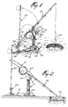
- the present invention concerns a fishing rig consisting of seven components including: a base 12, an upright 14, a triggering device 16, a fishing rod including a handle portion 18 and a pole portion 20, a flag with staff 22 and a fitting 24.
- the base 12 (see figure 5) is a unitary plastic molded member consisting of a longitudinal central member 26 and of a cross member 28, both of which are reinforced by the presence of opposite oblique side members 30 and 32, 34 and 36.
- the rear of the base displays an upstanding cylindrical hollow portion 38 while the front of the base displays, on the central member 26, two successive pairs of ears 40, 42 and 44, 46.
- the bottom face of the central member 26 between the pairs of ears is concave as explained further hereinbelow.
- Members 26 and 28 each have reinforcing ribs 27 and their extremities each have a hole 29 allowing the base to be fixed to the ice surface or other supporting surface.
- the upright 14 comprises a vertical portion 48 with a rounded base 50 which is adapted to be received between the two ears 40 and 42 and on the concave lower surface therebetween on the base.
- the upper portion of the upright 48 is rearwardly oblique and is defined by a pair of spaced side members 52 and 54 defining a yoke.
- a pair of cross-pins 56 and 57 extends transversely between the two members 52 and 54.
- the lower end of the upright has two opposite rounded flanges 58 which are adapted to sit and ride on the upper rounded edges of the ears 40 and 42.
- the lower end of the oblique side members 52 and 54 displays a rounded recess 62 at the front thereof.
- the triggering mechanism 16 is a T-shaped member 70 integrally formed, at its base, with a transverse pivot 66 having two grooved areas which are adapted to be fittingly inserted into the rounded recesses 62 of each member 52, 54 of the yoke.
- the opposite extremities of shaft 66 have a semi-spherical surface 66a; however, as as can be seen in figure 4, one extremity of this surface has a segmented portion 68, the function of which will be described hereinafter.
- the handle portion 18 of the fishing rod includes a hand gripping section 70, having a hook-like extremity 72, and a housing 74 which is formed of opposite circular side extensions 75.
- a reel 76 is rotatably secured in housing 74 by means of a manual lever 78 which has a rectangular cross-member 79. Openings are provided in both circular side extensions of the housing 74 so that lever 78 may be located on either side (for left-handed or right-handed fishermen).
- Portion 18 of the handle also comprises a C-shaped catch 80 defining an open slot 82 in which is positioned the cross-pin 56 of the upright which acts as a fulcrum point when the fishing rod is placed on the upright.
- the other portion 20 of the fishing rod comprises a standard pole 84 with circular rings 86 through which extends a fishing line 88, the pole being tight fitted in the extremity of the handle portion 18.
- the flag 22 consists of a visual signaling element 90 adjacent its extremity 22a and of a flexible staff 92.
- Fitting 24 comprises a cylindrical lower portion 94 which is adapted to be snuggly received in the hollow cylindrical extension 38 of the base. It further comprises, at the upper portion, two space side members 96 and 98 between which is adapted to sit the extremity 72 of the fishing rod.
- One side member 96 includes, on its outer wall, a cylindrical hollow housing 100 to receive the lower end of the flexible staff 92. Fitting 24 thus serves to support the flag as well as the fishing rod when in a tip-up position.
- the assembly of the fishing rig is accomplished as follows.
- the upright 14 is positioned vertically with its base 50 inserted between the two supporting ears 40 and 42 of the base.
- a locking pin 102 (see figure 1) is inserted through an appropriate side opening 103 in each ear in registry with hole 51 of the upright (see figure 3).
- the fishing rod is then positioned so that its catch 80 engages the cross pin 56 of the upright (as shown in figure 4); with the fishing rod placed in its tip-up position, extremity 72 of the rod is received between the two sides members 96 and 98 of fitting 24.
- the lower end of the flag staff is fitted in the cylindrical housing 100.
- the flag staff is then flexed and its upper extremity 22a is located to abut the segmented portion 68 of the end surface 66a of pivot 66.
- Line 88 is then pulled away from the pole and loosely fitted around the head 64 of the T-shaped portion of the triggering device.
- the triggering device 16 pivots about its axis 66 (as indicated by arrow 105). As the semi-spherical surface 66a, rotates, it slides under the staff extremity 22a thus releasing the staff to its normal vertical position (as indicated by arrow 106). Also, the line is freed from head 64.
- the fishing rod pivots about axis 56 and adopts the position shown in figure 2 with its tip down over hole 110.
- cross-pin 56 now slides in the uppermost extremity of slot 82 of catch 80.
- the obliqueness of portion 54 relative to the main vertical portion of the upright 14 provides maximum resistance to the pull in the direction 107 (in figure 2).
- the opposing force is in line with the pulling force of the rod. If the upright were in a vertical position, there would be a tendency for the entire assembly to pivot with the possibility of the rod being unhooked and being pulled into the hole.
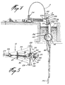
- Another feature of the present invention resides in the particular construction of the base 12, which allows fishing to be carried out in the manner shown in figure 7. This may be preferred in cases where movement of the fishing rod in the water is desired to effect continuous breakage of the thin ice 112 being formed on the surface of the water. Still, in cases where there is not sufficient movement of the rod to cause ice breakage, the retrieval of the fishing rod (as indicated by arrow 152 in figure 8) by pivoting the upright 14 about pivot 102 will break the thin ice layer.
- the upright is, in this case, positioned horizontally between the frontmost ears 44 and 46 of the base and is secured therebetween by means of a pin 102 with the opposite arcuate portions 58 resting on the corresponding upper edges of the ears (see figure 9).
- a ball-and-spring arrangement 120 may be used to secure the pin 102 in the assembly of the upright 14 to the base 12.
- the base includes an opening 122 rearwardly of ears 44 and 46 so that the lower cylindrical portion 94 of fitting 24 may be received therein (see figure 7).
- an elongate extension member 130 formed of two telescopically engaged members 132 and 134 is used. Each member has a C-shaped extremity 136, 138 for respectively engaging the cylindrical portion 140 of the lever 78 and one of the two side arms 142 of the T-shaped triggering device 16.
- the engagement of the flag staff extremity 22a with the triggering device 16 is accomplished in the same manner as that described above with respect to figures 1 to 6.
- a pull on line 88 in the direction of arrow 150 causes the rotation of the lever 78 and, through its telescopic connecting member 130, the pivotal movement of device 16 which then triggers the release of staff 22 again in the same manner as that described above.
- retrieval of the fishing rod is accomplished by simply pivoting the upright 14 about pin 102 in the direction of arrow 152.
- the base may be constructed in a manner that all of the other components of the rig may be snuggly received thereon. It is therefore wished to have it understood that the present invention should not be limited in scope, except by the terms of the following claims.
Landscapes
- Life Sciences & Earth Sciences (AREA)
- Environmental Sciences (AREA)
- Marine Sciences & Fisheries (AREA)
- Animal Husbandry (AREA)
- Biodiversity & Conservation Biology (AREA)
- Breeding Of Plants And Reproduction By Means Of Culturing (AREA)
- Eye Examination Apparatus (AREA)
- Measuring Or Testing Involving Enzymes Or Micro-Organisms (AREA)
- Lubrication Of Internal Combustion Engines (AREA)
- Control Of Throttle Valves Provided In The Intake System Or In The Exhaust System (AREA)
- Food-Manufacturing Devices (AREA)
Claims (19)
- Angelausrüstung mit, in Kombination:- Sockelmitteln (12), die dazu eingerichtet sind, in Gebrauch auf einer Stützfläche zu sitzen, und die einen vorderen Teil und einen hinteren Teil bilden,- Pfostenmitteln (14), die im Gebrauch an dem vorderen Teil der Sockelmittel (12) montiert sind und einen sich nach hinten erstreckenden schrägen oberen Teil aufweisen, der einen Drehpunkt darauf definiert,- einer kippbaren Angelrute (18, 20), die im Gebrauch an dem Drehpunkt montiert ist und erste und zweite Abschnitte auf beiden Seiten des Drehpunktes bildet, wobei der erste Abschnitt eine eine Schnur (88) tragende Stange (84) aufweist und der zweite Abschnitt einen Handgriff (18) und eine Schnur-Winde (76) aufweist, welche Rute weiterhin Mittel zum Montieren des oberen Teils an dem Drehpunkt aufweist,- Flaggenmitteln (22) mit einem flexiblen Stab (92), der mit seinem unteren Ende an dem hinteren Teil der Sockelmittel montiert ist,- Mitteln (24), die am hinteren Teil der Sockelmittel (12) angeordnet sind, und zur Aufnahme des unteren Endes des flexiblen Stabes (92) sowie zur Abstützung des zweiten Abschnitts (18) der Angelrute, und- Auslösemitteln (16), die schwenkbar an den Pfostenmitteln (14) montiert sind und Schnur-Eingriffsmittel (64) und Flaggen-Eingriffsmittel (68) aufweisen, die dazu eingerichtet sind, mit einem entgegengesetzten Ende (22a) des Stabes (92) in Berührung zu kommen, wenn dieser gebogen ist, wodurch eine Zugkraft auf die Schnur ein Schwenken der Auslösemittel verursacht, um so das entgegengesetzte Ende des Stabes freizugeben.
- Angelausrüstung nach Anspruch 1, bei der die Auslösemittel (16) aus einem Körper bestehen, der aufweist:a) eine Schwenkachse (66), die an ihrem einen Ende Oberflächenmittel hat, die dazu eingerichtet sind, mit dem entgegengesetzten Ende des Stabes (92) in Anschlagsberührung zu kommen, undb) einen Schaft, dessen eines Ende mit der Achse einstückig ist und dessen entgegengesetztes Ende (64) die Schnur (88) frei aufnimmt, wobei die Schnur (88) von dem entgegengesetzten Ende freigegeben wird, wenn die Zugkraft auf die Schnur die Anschlagsberührung aufhebt und dadurch die Schwenkbewegung der Achse und das Lösen des entgegengesetzten Endes des Stabes von den Oberflächenmitteln verursacht.
- Angelausrüstung nach Anspruch 2, bei der die Oberflächenmittel segmentförmig sind, wobei das entgegengesetzte Ende des Stabes die segmentförmigen Oberflächenmittel berührt.
- Angelausrüstung nach Anspruch 2 oder 3, bei der der Schaft T-förmig ist.
- Angelausrüstung nach Anspruch 2, bei der die Auslösemittel an der Basis des schrägen oberen Teils der Pfostenmittel montiert sind.
- Angelausrüstung nach Anspruch 5, bei der der schräge obere Teil die Form eines Joches hat.
- Angelausrüstung nach Anspruch 6, bei der der Drehpunkt aus einem querverlaufenden Stift besteht, der sich im oberen Teil des Joches erstreckt.
- Angelausrüstung nach Anspruch 6 oder 7, die weiterhin einen Querstift in dem Joch aufweist, um darauf die Schnur aufzunehmen, die sich zwischen der Winde und den Auslösemitteln erstreckt.
- Angelausrüstung nach Anspruch 7, bei der die Mittel zum Montieren des oberen Teils an dem Drehpunkt an der Angelrute aus einem C-förmigen Element bestehen, in dem der querverlaufende Stift aufgenommen ist.
- Angelausrüstung nach Anspruch 1, die am hinteren Teil der Basis einen lösbaren Halter zur Aufnahme des unteren Endes des flexiblen Stabes aufweist.
- Angelausrüstung nach Anspruch 10, bei der der Halter Mittel zur Aufnahme eines hinteren Endes des Handgriffes der Angelrute auweist.
- Angelausrüstung nach Anspruch 1, die weiterhin lösbare Zapfenmittel zum in Eingriff Bringen des unteren Endes der Pfostenmittel mit dem vorderen Teil des Sockels aufweist.
- Ausrüstung zum Angeln an einem in eine Eisfläche geschnittenen Loch, mit, in Kombination:- Sockelmitteln (12), die dazu eingerichtet sind, im Gebrauch auf der Eisfläche zu sitzen,- Haltemitteln (14), die im Gebrauch mit einem Ende an den Sockelmitteln (12) montiert sind und deren entgegengesetztes Ende dazu eingerichtet ist, sich über das Loch zu erstrecken,- einer Angelrute, die im Gebrauch an dem entgegengesetzten Ende der Haltemittel aufgehängt ist und sich nach unten durch das Loch erstreckt, welche Rute eine eine Schnur (88) tragende Stange (84), eine drehbare Schnur-Winde (76) und einen Handgriff (18) aufweist, wobei die Schnur-Winde (74) einen handbetätigbaren Hebel (140) aufweist,- Flaggenmitteln (22) mit einem flexiblen Stab (92), der mit seinem unteren Ende an den Sockelmitteln montiert ist, und- Flaggen-Auslösemitteln (16), die schwenkbar am entgegengesetzten Endbereich der Haltemittel (14) montiert sind und aufweisen: Stab-Eingriffsmit tel (68), die dazu eingerichtet sind, ein entgegengesetztes Ende (22a) des Stabes (92) zu berühren, wenn er sich in einem gebogenen Zustand befindet, und Verlängerungsmittel (130), die mit einem Ende gelenkig mit den Flaggen-Auslösemitteln und mit dem anderen Ende gelenkig mit dem Hebel (140) verbunden sind, wodurch eine Zugkraft auf die Schnur eine Drehung der Winde und des Hebels verursacht und folglich, über die Verlängerungsmittel (130), die Auslösemittel veranlaßt, das entgegengesetzte Ende (22a) des Stabes freizugeben.
- Angelausrüstung nach Anspruch 13, bei der die Flaggen-Eingriffsmittel aus (a) einer Schwenkachse, die an ihrem einen Ende mit Oberflächenmitteln für die Anschlagberührung des entgegengesetzten Endes der Flagge versehen ist, und (b) einem Schaft besteht, der Mittel besitzt, die das eine Ende der Teleskopmittel aufnehmen.
- Angelausrüstung nach Anspruch 14, bei der die Oberflächenmittel segmentförmig sind, wobei das entgegengesetzte Ende der Flagge an den segmentförmigen Oberflächenmitteln anliegt.
- Angelausrüstung nach Anspruch 13, bei der das entgegengesetzte Ende der Haltemittel die Form eines Joches hat, in dem ein querverlaufender Stift angeordnet ist.
- Ausrüstung nach Anspruch 16, bei der der Handgriff der Angelrute an seinem einen Ende Hakenmittel aufweist, die dazu eingerichtet sind, frei an dem querverlaufenden Stift aufgehängt zu werden.
- Angelausrüstung nach Anspruch 13, die weiterhin lösbare Zapfenmittel zum in Eingriff Bringen des einen Endes der Haltemittel an dem Sockel aufweist.
- Angelausrüstung nach Anspruch 13, die weiterhin Mittel aufweist, die dazu eingerichtet sind, an dem Sockel montiert zu werden, um das untere Ende der Flaggenmittel aufzunehmen.
Applications Claiming Priority (3)
| Application Number | Priority Date | Filing Date | Title |
|---|---|---|---|
| CA002027879A CA2027879A1 (en) | 1990-10-17 | 1990-10-17 | Fishing rig |
| CA2027879 | 1990-10-17 | ||
| PCT/CA1991/000371 WO1992006593A1 (en) | 1990-10-17 | 1991-10-17 | Fishing rig |
Publications (2)
| Publication Number | Publication Date |
|---|---|
| EP0553227A1 EP0553227A1 (de) | 1993-08-04 |
| EP0553227B1 true EP0553227B1 (de) | 1994-06-15 |
Family
ID=4146182
Family Applications (1)
| Application Number | Title | Priority Date | Filing Date |
|---|---|---|---|
| EP91919308A Expired - Lifetime EP0553227B1 (de) | 1990-10-17 | 1991-10-17 | Takelage zum angeln |
Country Status (7)
| Country | Link |
|---|---|
| EP (1) | EP0553227B1 (de) |
| AT (1) | ATE107127T1 (de) |
| AU (1) | AU8665091A (de) |
| CA (1) | CA2027879A1 (de) |
| DE (1) | DE69102539D1 (de) |
| FI (1) | FI931732A7 (de) |
| WO (1) | WO1992006593A1 (de) |
Families Citing this family (3)
| Publication number | Priority date | Publication date | Assignee | Title |
|---|---|---|---|---|
| AU651306B3 (en) * | 1992-11-02 | 1994-07-14 | Wayne John Blundell | Angling assembly |
| US5519958A (en) * | 1994-12-16 | 1996-05-28 | Koretz; Darren | Ice fishing rig |
| US8881445B2 (en) * | 2011-05-20 | 2014-11-11 | Linda K. Nolf | Tip up fishing device |
Family Cites Families (6)
| Publication number | Priority date | Publication date | Assignee | Title |
|---|---|---|---|---|
| US2565379A (en) * | 1945-07-13 | 1951-08-21 | Never Fail Products Co Inc | Tipup |
| US2970400A (en) * | 1958-08-05 | 1961-02-07 | Earl W Nolin | Fishing apparatus |
| US3824730A (en) * | 1973-06-27 | 1974-07-23 | R Johnson | Fishing rod holder |
| US3888035A (en) * | 1974-03-18 | 1975-06-10 | Ralph P Totten | Ice fishing rod |
| US4373287A (en) * | 1980-10-03 | 1983-02-15 | Grahl Paul F | Fishing tip-up |
| US4837965A (en) * | 1988-04-14 | 1989-06-13 | True Donovan B | Ice fishing tip-up |
-
1990
- 1990-10-17 CA CA002027879A patent/CA2027879A1/en not_active Abandoned
-
1991
- 1991-10-17 EP EP91919308A patent/EP0553227B1/de not_active Expired - Lifetime
- 1991-10-17 AU AU86650/91A patent/AU8665091A/en not_active Abandoned
- 1991-10-17 AT AT91919308T patent/ATE107127T1/de not_active IP Right Cessation
- 1991-10-17 DE DE69102539T patent/DE69102539D1/de not_active Expired - Lifetime
- 1991-10-17 WO PCT/CA1991/000371 patent/WO1992006593A1/en not_active Ceased
-
1993
- 1993-04-16 FI FI931732A patent/FI931732A7/fi not_active Application Discontinuation
Also Published As
| Publication number | Publication date |
|---|---|
| WO1992006593A1 (en) | 1992-04-30 |
| AU8665091A (en) | 1992-05-20 |
| DE69102539D1 (de) | 1994-07-21 |
| ATE107127T1 (de) | 1994-07-15 |
| FI931732A7 (fi) | 1993-05-25 |
| CA2027879A1 (en) | 1992-04-18 |
| EP0553227A1 (de) | 1993-08-04 |
| FI931732A0 (fi) | 1993-04-16 |
Similar Documents
| Publication | Publication Date | Title |
|---|---|---|
| US5050333A (en) | Fishing rig | |
| US4161839A (en) | Swivel device for supporting a balanced or semi-balanced fishing rod and indicating when a fish strikes | |
| US4837965A (en) | Ice fishing tip-up | |
| US4676019A (en) | Fishing rod holder | |
| US4676018A (en) | Automatic hook setter and fishing rod holder | |
| US5491923A (en) | Fishing pole holder | |
| US5245778A (en) | Fishing pole holder and hook device | |
| US5063373A (en) | Fishing rod holder with fish alert | |
| US5488796A (en) | Fishing line sensor | |
| US5369905A (en) | Slider and stop attachment for a fishing line | |
| US5570532A (en) | Fish strike sensor | |
| US4146988A (en) | Fishing rod tip-up | |
| US4829697A (en) | Fishing gear | |
| US3973346A (en) | Fishing pole holder | |
| US6493981B2 (en) | Slip bobber with hook setting device | |
| US2628443A (en) | Fishing apparatus | |
| US5339558A (en) | Ice fishing devices | |
| US6354036B1 (en) | Fishing tip-up device | |
| US4581838A (en) | Fishing rod holder | |
| CA1045379A (en) | Downrigger release mechanism | |
| WO1992006593A1 (en) | Fishing rig | |
| US3293789A (en) | Fishing rod holder | |
| US5501027A (en) | Fishing pole alert device | |
| US5669175A (en) | Fish strike indicator apparatus | |
| US5077928A (en) | Fishing line rod bobber |
Legal Events
| Date | Code | Title | Description |
|---|---|---|---|
| PUAI | Public reference made under article 153(3) epc to a published international application that has entered the european phase |
Free format text: ORIGINAL CODE: 0009012 |
|
| 17P | Request for examination filed |
Effective date: 19930416 |
|
| AK | Designated contracting states |
Kind code of ref document: A1 Designated state(s): AT BE CH DE DK ES FR GB GR IT LI LU NL SE |
|
| 17Q | First examination report despatched |
Effective date: 19931008 |
|
| GRAA | (expected) grant |
Free format text: ORIGINAL CODE: 0009210 |
|
| AK | Designated contracting states |
Kind code of ref document: B1 Designated state(s): AT BE CH DE DK ES FR GB GR IT LI LU NL SE |
|
| PG25 | Lapsed in a contracting state [announced via postgrant information from national office to epo] |
Ref country code: IT Free format text: LAPSE BECAUSE OF FAILURE TO SUBMIT A TRANSLATION OF THE DESCRIPTION OR TO PAY THE FEE WITHIN THE PRE;WARNING: LAPSES OF ITALIAN PATENTS WITH EFFECTIVE DATE BEFORE 2007 MAY HAVE OCCURRED AT ANY TIME BEFORE 2007. THE CORRECT EFFECTIVE DATE MAY BE DIFFERENT FROM THE ONE RECORDED.SCRIBED TIME-LIMIT Effective date: 19940615 Ref country code: ES Free format text: THE PATENT HAS BEEN ANNULLED BY A DECISION OF A NATIONAL AUTHORITY Effective date: 19940615 Ref country code: AT Effective date: 19940615 Ref country code: NL Effective date: 19940615 Ref country code: LI Effective date: 19940615 Ref country code: FR Effective date: 19940615 Ref country code: DK Effective date: 19940615 Ref country code: GR Free format text: LAPSE BECAUSE OF FAILURE TO SUBMIT A TRANSLATION OF THE DESCRIPTION OR TO PAY THE FEE WITHIN THE PRESCRIBED TIME-LIMIT Effective date: 19940615 Ref country code: CH Effective date: 19940615 Ref country code: BE Effective date: 19940615 |
|
| REF | Corresponds to: |
Ref document number: 107127 Country of ref document: AT Date of ref document: 19940715 Kind code of ref document: T |
|
| REF | Corresponds to: |
Ref document number: 69102539 Country of ref document: DE Date of ref document: 19940721 |
|
| PG25 | Lapsed in a contracting state [announced via postgrant information from national office to epo] |
Ref country code: DE Effective date: 19940916 |
|
| PGFP | Annual fee paid to national office [announced via postgrant information from national office to epo] |
Ref country code: SE Payment date: 19940927 Year of fee payment: 4 |
|
| REG | Reference to a national code |
Ref country code: CH Ref legal event code: PL |
|
| PG25 | Lapsed in a contracting state [announced via postgrant information from national office to epo] |
Ref country code: LU Free format text: LAPSE BECAUSE OF NON-PAYMENT OF DUE FEES Effective date: 19941031 |
|
| EN | Fr: translation not filed | ||
| NLV1 | Nl: lapsed or annulled due to failure to fulfill the requirements of art. 29p and 29m of the patents act | ||
| EAL | Se: european patent in force in sweden |
Ref document number: 91919308.6 |
|
| PLBE | No opposition filed within time limit |
Free format text: ORIGINAL CODE: 0009261 |
|
| STAA | Information on the status of an ep patent application or granted ep patent |
Free format text: STATUS: NO OPPOSITION FILED WITHIN TIME LIMIT |
|
| 26N | No opposition filed | ||
| PG25 | Lapsed in a contracting state [announced via postgrant information from national office to epo] |
Ref country code: GB Effective date: 19951017 |
|
| PG25 | Lapsed in a contracting state [announced via postgrant information from national office to epo] |
Ref country code: SE Effective date: 19951018 |
|
| GBPC | Gb: european patent ceased through non-payment of renewal fee |
Effective date: 19951017 |
|
| EUG | Se: european patent has lapsed |
Ref document number: 91919308.6 |