EP0553602A2 - Vorrichtung und Verfahren zum Laden von rechteckigen Ballen, insbesondere Riesenballen von Heu oder dergleichen - Google Patents
Vorrichtung und Verfahren zum Laden von rechteckigen Ballen, insbesondere Riesenballen von Heu oder dergleichen Download PDFInfo
- Publication number
- EP0553602A2 EP0553602A2 EP92830581A EP92830581A EP0553602A2 EP 0553602 A2 EP0553602 A2 EP 0553602A2 EP 92830581 A EP92830581 A EP 92830581A EP 92830581 A EP92830581 A EP 92830581A EP 0553602 A2 EP0553602 A2 EP 0553602A2
- Authority
- EP
- European Patent Office
- Prior art keywords
- bale
- platform
- bales
- loading
- axis
- Prior art date
- Legal status (The legal status is an assumption and is not a legal conclusion. Google has not performed a legal analysis and makes no representation as to the accuracy of the status listed.)
- Granted
Links
Images





Classifications
-
- A—HUMAN NECESSITIES
- A01—AGRICULTURE; FORESTRY; ANIMAL HUSBANDRY; HUNTING; TRAPPING; FISHING
- A01D—HARVESTING; MOWING
- A01D90/00—Vehicles for carrying harvested crops with means for selfloading or unloading
- A01D90/02—Loading means
- A01D90/08—Loading means with bale-forming means additionally used for loading; with means for picking-up bales and transporting them into the vehicle
-
- A—HUMAN NECESSITIES
- A01—AGRICULTURE; FORESTRY; ANIMAL HUSBANDRY; HUNTING; TRAPPING; FISHING
- A01D—HARVESTING; MOWING
- A01D87/00—Loaders for hay or like field crops
- A01D87/12—Loaders for sheaves, stacks or bales
- A01D87/122—Loaders for sheaves, stacks or bales for bales on the ground
Definitions
- the present invention relates in general to machines for picking up square bales of hay, straw and the like.
- Such machines have the primary function to avoid for the users any fatigue due to the lifting of the bales from the ground, on which they have been placed previously by a baling press, up to a loading platform of a vehicle adapted to transfer such bales to a stocking place, where they are unloaded in order to be preserved up to the moment of their use.
- the known machines of the above indicated type are generally able merely to lift the bales, whereas one or more operators above the loading platform of the transport vehicle attend to methodically arranging the loaded bales so that when the loading platform is tilted, the bales are arranged in orderly piles to optimize the room available in the stocking places.
- bales are of big size. It is here the case, in particular, of giant square bales, which have the shape of a square block having a length of about 240/250 cm, whose rectangular base has sides whose size may be 60X90 cm, 80X80 cm, 90X90 cm, 90X120 cm or 120X120 cm. Because of such huge size, each of such bales may weigh up to 450 Kg, which renders impossible for them to be handled by one or a few operators.
- such giant square bales are handled by a loading machine which attends to lifting the bales from the ground and load them methodically on the transport vehicle, for example associated with a tractor, the loading machine being independent from the vehicle on which the bales are loaded, thus requiring the use of a suitably adapted mechanical means, as well as of an operator for driving the latter, in addition to the transport vehicle and its driver.
- the main object of the present invention is to provide a machine for loading and unloading square bales, particularly giant square bales, adapted to pick up bales from the ground and load such bales on a transport vehicle piling up methodically the bales on the latter, under the control of a single operator.
- a wheeled vehicle having a supporting frame and a loading platform which is tiltable between a lowered position for receiving the bales and a raised position to unload the loaded bales, said vehicle further having: pushing means associated with the loading platform for pushing a plurality of loaded bales along a direction parallel to the platform from the loading end of the platform towards the opposite end, loading means for picking up a bale from the ground and releasing said bale on the platform, said means comprising a movable arm having one end articulated to the vehicle frame around a first axis which is substantially perpendicular to the platform and a second axis orthogonal to said first axis, and an opposite end carrying a grasping clamp, driving means for driving said pushing means and said loading means, said driving means being adapted to drive said movable arm so as to cause the same to take in sequence the following positions at any loading cycle: a first substantially horizontal position for grasping a bale to be loaded, lying on the ground and arranged with its general axis substantially parallel to the longitudinal
- the movable arm also takes, before unloading the bale, at any loading cycle, a final unloading position rotated with respect to said third position around said second axis, in which the bale is arranged on the vertical of a free loading space.
- the machine according to the present invention can grasp and raise the bales, as well as put them on the loading platform in a position suitable to be subsequently unloaded in orderly piles, with the use of a single means driven by a single operator.
- the loading and unloading operations of the bales are rendered particurarly simple and easy and require a reduced time to be carried out, to the advantage of the overall costs of the operations for collecting hay or forage bales.
- the present invention is also directed to a method for picking up square bales, carried out by means of the above described machine.
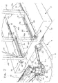
- FIG. 1 a machine is shown therein for picking up square bales, including a trailer generally indicated with reference numeral 1.
- the machine comprises a frame 3 movable on two pairs of wheels 5, which pivotally supports, around an axis 9, a platform 7 having a front end 7a and a rear end 7b.
- the general structure of frame 3 and platform 7 may be of any known type, for example of the type illustrated in European Patent Application EP-0 079 315.
- the machine is comprised of a trailer which can be towed by an agricultural tractor (illustrated by dotted lines). However agricultural tractor (illustrated by dotted lines). However it is apparent that the machine could be provided as a self-propelled machine.
- the frame 3 of the trailer comprises a drawbar 11 which has a coupling device 11a for engagement with a cooperating member (not shown) associated with the agricultural tractor.
- a hydraucally operated mechanical arm 13 which comprises two profiled elements 13a and 13b telescopically mounted onto each other, and which carries at its free end a clamp 15 adapted to pick up square bales 17 of hay and the like from the ground and to unload such bales on the platform 7.
- a control unit 19 arranged for example on the towing vehicle, drives the functions of a hydraulic pump 21 which is rigidly connected to the drawbar 11 of the trailer in proximity of the articulation of arm 13, to drive the operations of the whole machine, as it will be described with more details in the following.
- Pump 21 is mechanically driven by taking power from the towing vehicle by means of a shaft 23 connected at one end to the power take-off (not shown) of the agricultural tractor and at its other end to pump 21 by means of a cardan joint 25.
- the articulation of arm 13 comprises a first support element 27 anchored to the frame of trailer 3, on which there is rotatabl mounted, around a vertical axis 30, a turret unit 29.
- Unit 29 carries on one side a bracket 31 whose end 31a is passed through by a vertical pin 32 on which one end of a hydraulic jack 33 is engaged.
- the opposite end of jack 33 is articulated on a support 35 anchored to frame 3.
- unit 29 In its upper part, unit 29 carries a transverse pin 27 having an axis 38, on which one end of element 13a of arm 13 is articulated.
- the unit 29, at a position diametrically opposed to bracket 31, has a fork element 39 through which there is passed a horizontal pin 41 which engages one end of a second hydraulic jack 43 whose other end is engaged by another horizontal pin 45 carried by the first element 13a of arm 13 in proximity to its end which is remote from the articulation pin 37.
- the second element 13b of arm 13 has a cross section which is smaller of the first element 13a and is able to slide inside the latter.
- a series of holes 47 are arranged transversally to element 13b, so that the latter may be fixed in a number of possible alternative positions, by means of a key 49 which engages a hole of first element 13a of arm 13 and one of holes 47 of element 13b.
- a key 49 which engages a hole of first element 13a of arm 13 and one of holes 47 of element 13b.
- the clamp 15 which comprises a support structure 51 from which square support arms 53 project telescopically, which support a L-shaped abutment element 55.
- Element 55 is provided with end wings 56 and 57, respectively including a shoulder and a baffle, to favour abutment against the side walls of a bale to be loaded.
- Fork elements 59 project from the upper part of structure 51 and have respective pins which carry a tilting jaw 63 operated by a hydraulic jack 67.
- the jaw 63 comprises two square arms 61 which carry a flat element 65 extending parallel to the L-shaped abutment element 55.
- the abutment element 55 is provided in order to adapt itself to different sizes of straw bales to be loaded and its distance from the fixed structure 51 can be adjusted by inserting a key 71 in any hole among a number of holes 69 arranged transversally with respect to arms 53 of element 55.
- the platform 7, at its rear end side 7b, adjacent to articulation 9 carries two parallel blades 73 which extend vertically, whose function is to make unloading of the bales from platform 7 easier.
- Uprights 75a and 75b comprise element 76 orthogonal thereto which constitute sliding members within slots 77 which extend longitudinally along a portion of the platform adiacent to the front end 7a.
- baffle plate 79 To the uprights 75a and 75b there is associated a baffle plate 79, whose function is to address correctly a bale during loading thereof on the platform, the plate 79 being supported by damping stems 81 which are respectively articulated adiacent to the bases of uprights 75a and 75b.
- damping stems 81 which are respectively articulated adiacent to the bases of uprights 75a and 75b.
- each comprise a vertical stem 85 and a respective planar portion 87, orthogonal to stem 85, each slidably supported along a respective guiding track 89 arranged longitudinally on platform 7 and extending throughout the whole length thereof.
- chains 91 Inside guiding track 89 there are arranged chains 91 to drive sliding of the support elements 83 along the same.
- uprights 75a and 75b may be rigidly connected to the end 7a of frame 7 and elements 83 are connected with toothed chains slidable in tracks 89.
- Such chains are provided with teeth projecting upwardly from the surface of platform 7 to displace the loaded bales from end 7a towards end 7b.
- machine 1 is towed by the tractor in the direction of arrow A along a path on which square bales having their direction of maximum length parallel to direction A have been previously layed down, for example by a baling press.
- the tractor moves parallel to the longitudinal direction of the bales until clamp 15 is in proximity of one of them.
- a bale 17a is surrounded by the abutment member 55, correctly addressed by baffle 57, until the rear wall of the bale impinges against shoulder 56.
- jaw 63 of the clamp is driven by jack 67 in order to move the jaw towards the abutment member 55, along the direction indicated by arrow B of figure 4, so as to tightly grasp bale 17a.
- jack 43 is then extended so as to raise the whole arm 13 and clamp 15 with the bale 17a.
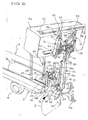
- the arm makes a rotation around the axis 38 slightly greater than 90°, as indicated by arrow C of figure 5 reaching a substantially vertical position.
- jack 33 is operated so as to cause the whole arm 13 to rotate of 90° around axis 30, until it brings bale 17a in a position transverse to the platform 7.
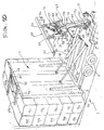
- bale 17a is on the vertical of the space free for loading, i.e. above the space between uprights 75a and 75b on one side and between stems 83 on the other side.
- Uprights 75 and 75b are then again advanced in the original loading position by operating jacks 82 so as to locate again the uprights at the front end 7 of platform 7
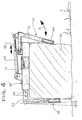
- the tractor attends to transfer the trailer 1 to a stocking place in which all the loaded straw bales will be simultaneously unloaded by rotating platform 7 around articulation 9 as a result of the pushing action generated by a pair of jacks 95 whose ends are respectively articulated to frame 3 and platform 7 (figure 10).
- Each stage of the movement of arm 13 during the loading operation of the bale can be carried out individually by operating a respective hydraulic jack through the levers associated with unit 19, or by operating a push bottom which causes the automatic operation of a sequence of various stages according to a predetermined sequence.
Landscapes
- Life Sciences & Earth Sciences (AREA)
- Environmental Sciences (AREA)
- Storage Of Harvested Produce (AREA)
- Preliminary Treatment Of Fibers (AREA)
- Loading Or Unloading Of Vehicles (AREA)
- Absorbent Articles And Supports Therefor (AREA)
Applications Claiming Priority (2)
| Application Number | Priority Date | Filing Date | Title |
|---|---|---|---|
| ITTO910795 | 1991-10-23 | ||
| ITTO910795A IT1249860B (it) | 1991-10-23 | 1991-10-23 | Macchina e procedimento per la raccolta di balle parallelepipede, particolarmente di tipo gigante, di fieno e simili. |
Publications (3)
| Publication Number | Publication Date |
|---|---|
| EP0553602A2 true EP0553602A2 (de) | 1993-08-04 |
| EP0553602A3 EP0553602A3 (en) | 1993-09-22 |
| EP0553602B1 EP0553602B1 (de) | 1996-03-06 |
Family
ID=11409658
Family Applications (1)
| Application Number | Title | Priority Date | Filing Date |
|---|---|---|---|
| EP92830581A Expired - Lifetime EP0553602B1 (de) | 1991-10-23 | 1992-10-23 | Vorrichtung und Verfahren zum Laden von rechteckigen Ballen, insbesondere Riesenballen von Heu oder dergleichen |
Country Status (4)
| Country | Link |
|---|---|
| EP (1) | EP0553602B1 (de) |
| AT (1) | ATE134826T1 (de) |
| DE (1) | DE69208859T2 (de) |
| IT (1) | IT1249860B (de) |
Cited By (10)
| Publication number | Priority date | Publication date | Assignee | Title |
|---|---|---|---|---|
| GB2266698B (en) * | 1992-04-16 | 1996-04-03 | Roberts & Griffiths | A Vehicle for Handling Round Bales |
| DE19540691A1 (de) * | 1995-11-02 | 1997-05-07 | Same Spa | Ballentransportwagen für Großballen |
| GB2307675A (en) * | 1995-12-02 | 1997-06-04 | John Dowson Walton | Bale Processing Machine |
| FR2743690A1 (fr) * | 1996-01-24 | 1997-07-25 | Levesque Jean Marc | Remorque auto-chargeuse de balles de paille |
| FR2791657A1 (fr) * | 1999-04-02 | 2000-10-06 | Patrice Denis | Appareil de chargement de fardeaux pre cercles |
| NL1012446C2 (nl) * | 1999-06-25 | 2000-12-28 | Schuitemaker Mach Bv | Kleminrichting voor het oppakken van balen zoals graspakken. |
| US6220811B1 (en) * | 1998-08-20 | 2001-04-24 | Michael J. Bernecker | Apparatus and method for handling and transporting bales |
| WO2010015033A1 (en) | 2008-08-06 | 2010-02-11 | Ashmore Engineering Pty Ltd | Hay bale stacker |
| CN108834580A (zh) * | 2018-08-17 | 2018-11-20 | 许孜怡 | 农牧业多功能一体机 |
| KR20220000863A (ko) * | 2020-06-26 | 2022-01-04 | 엘앤에스(주) | 적재차량과 운반차량을 이용한 화물 운반 및 적재 시스템 |
Family Cites Families (5)
| Publication number | Priority date | Publication date | Assignee | Title |
|---|---|---|---|---|
| DE1657049A1 (de) * | 1968-01-16 | 1971-07-01 | Kemper Kg Wilhelm | Ballen-Ladewagen |
| US3771678A (en) * | 1971-03-16 | 1973-11-13 | Pattersons Venture Ltd | Loader |
| DK510074A (da) * | 1974-09-27 | 1976-03-28 | Bay Schmith N | Fremgangsmade til at lesse afgrodeballer eller lignende enheder pa et koretoj og apparat til brug ved udovelse af fremgangsmaden |
| FR2454258A1 (fr) * | 1979-04-20 | 1980-11-14 | Maitre Ets | Procede et dispositif pour le chargement des bottes telles que de fourrage sur une remorque dite auto-chargeuse-dechargeuse |
| US4552501A (en) * | 1982-09-15 | 1985-11-12 | Clark Raymond W | Big bale handling system |
-
1991
- 1991-10-23 IT ITTO910795A patent/IT1249860B/it active IP Right Grant
-
1992
- 1992-10-23 AT AT92830581T patent/ATE134826T1/de not_active IP Right Cessation
- 1992-10-23 DE DE69208859T patent/DE69208859T2/de not_active Expired - Fee Related
- 1992-10-23 EP EP92830581A patent/EP0553602B1/de not_active Expired - Lifetime
Cited By (14)
| Publication number | Priority date | Publication date | Assignee | Title |
|---|---|---|---|---|
| GB2266698B (en) * | 1992-04-16 | 1996-04-03 | Roberts & Griffiths | A Vehicle for Handling Round Bales |
| DE19540691A1 (de) * | 1995-11-02 | 1997-05-07 | Same Spa | Ballentransportwagen für Großballen |
| GB2307675A (en) * | 1995-12-02 | 1997-06-04 | John Dowson Walton | Bale Processing Machine |
| GB2307675B (en) * | 1995-12-02 | 1999-03-03 | John Dowson Walton | Bale collecting machine |
| FR2743690A1 (fr) * | 1996-01-24 | 1997-07-25 | Levesque Jean Marc | Remorque auto-chargeuse de balles de paille |
| US6220811B1 (en) * | 1998-08-20 | 2001-04-24 | Michael J. Bernecker | Apparatus and method for handling and transporting bales |
| FR2791657A1 (fr) * | 1999-04-02 | 2000-10-06 | Patrice Denis | Appareil de chargement de fardeaux pre cercles |
| NL1012446C2 (nl) * | 1999-06-25 | 2000-12-28 | Schuitemaker Mach Bv | Kleminrichting voor het oppakken van balen zoals graspakken. |
| WO2010015033A1 (en) | 2008-08-06 | 2010-02-11 | Ashmore Engineering Pty Ltd | Hay bale stacker |
| AU2009251025B2 (en) * | 2008-08-06 | 2010-07-15 | Ashmore Engineering Pty Ltd | Hay bale stacker |
| EP2337440A4 (de) * | 2008-08-06 | 2012-12-19 | Ashmore Engineering Pty Ltd | Heuballenstapler |
| US8585342B2 (en) | 2008-08-06 | 2013-11-19 | Ashmore Engineering Pty Ltd | Hay bale stacker |
| CN108834580A (zh) * | 2018-08-17 | 2018-11-20 | 许孜怡 | 农牧业多功能一体机 |
| KR20220000863A (ko) * | 2020-06-26 | 2022-01-04 | 엘앤에스(주) | 적재차량과 운반차량을 이용한 화물 운반 및 적재 시스템 |
Also Published As
| Publication number | Publication date |
|---|---|
| ATE134826T1 (de) | 1996-03-15 |
| ITTO910795A0 (it) | 1991-10-23 |
| DE69208859D1 (de) | 1996-04-11 |
| DE69208859T2 (de) | 1996-09-12 |
| IT1249860B (it) | 1995-03-28 |
| ITTO910795A1 (it) | 1993-04-23 |
| EP0553602A3 (en) | 1993-09-22 |
| EP0553602B1 (de) | 1996-03-06 |
Similar Documents
| Publication | Publication Date | Title |
|---|---|---|
| US4459075A (en) | Roll bale loader | |
| US5507612A (en) | Large bale handling apparatus | |
| US5397208A (en) | Large bale handling apparatus | |
| US5211345A (en) | Large bale handling apparatus | |
| US5082413A (en) | Bale carrying apparatus | |
| EP0553602B1 (de) | Vorrichtung und Verfahren zum Laden von rechteckigen Ballen, insbesondere Riesenballen von Heu oder dergleichen | |
| US5697758A (en) | Method for stacking rectangular big bales | |
| US4634336A (en) | Bale loader | |
| US6220811B1 (en) | Apparatus and method for handling and transporting bales | |
| EP2337440B1 (de) | Heuballenstapler | |
| US4363583A (en) | Hay bale loader | |
| US5899652A (en) | Hay bale transporter | |
| US7419345B2 (en) | Big bale loader, hauler and stacker | |
| US7887275B2 (en) | Bale handling vehicle | |
| US6079926A (en) | Self-propelled hay bale retriever and stacker | |
| US3241695A (en) | Load gripper and positioning device | |
| US3948553A (en) | Method of harvesting tobacco and apparatus for bulk handling the harvested tobacco | |
| US3529735A (en) | Bale lifting apparatus | |
| GB2040865A (en) | Bale loading and transporting machine | |
| US5478194A (en) | Method for stacking rectangular big bales | |
| US4911491A (en) | Modular bale handling apparatus with plurality of bale pick-up devices | |
| US4148399A (en) | Bale handling apparatus | |
| US4204789A (en) | Pass through hay bale retriever | |
| EP0079315B1 (de) | Lade- und Entladegerät für runde Heuballen und dergleichen | |
| US2962177A (en) | Bale loader and stacker |
Legal Events
| Date | Code | Title | Description |
|---|---|---|---|
| PUAI | Public reference made under article 153(3) epc to a published international application that has entered the european phase |
Free format text: ORIGINAL CODE: 0009012 |
|
| PUAL | Search report despatched |
Free format text: ORIGINAL CODE: 0009013 |
|
| AK | Designated contracting states |
Kind code of ref document: A2 Designated state(s): AT DE ES FR GB NL |
|
| AK | Designated contracting states |
Kind code of ref document: A3 Designated state(s): AT DE ES FR GB NL |
|
| 17P | Request for examination filed |
Effective date: 19940204 |
|
| 17Q | First examination report despatched |
Effective date: 19950811 |
|
| GRAH | Despatch of communication of intention to grant a patent |
Free format text: ORIGINAL CODE: EPIDOS IGRA |
|
| GRAA | (expected) grant |
Free format text: ORIGINAL CODE: 0009210 |
|
| AK | Designated contracting states |
Kind code of ref document: B1 Designated state(s): AT DE ES FR GB NL |
|
| PG25 | Lapsed in a contracting state [announced via postgrant information from national office to epo] |
Ref country code: NL Free format text: LAPSE BECAUSE OF FAILURE TO SUBMIT A TRANSLATION OF THE DESCRIPTION OR TO PAY THE FEE WITHIN THE PRESCRIBED TIME-LIMIT Effective date: 19960306 Ref country code: ES Free format text: THE PATENT HAS BEEN ANNULLED BY A DECISION OF A NATIONAL AUTHORITY Effective date: 19960306 Ref country code: AT Effective date: 19960306 |
|
| REF | Corresponds to: |
Ref document number: 134826 Country of ref document: AT Date of ref document: 19960315 Kind code of ref document: T |
|
| REF | Corresponds to: |
Ref document number: 69208859 Country of ref document: DE Date of ref document: 19960411 |
|
| ET | Fr: translation filed | ||
| NLV1 | Nl: lapsed or annulled due to failure to fulfill the requirements of art. 29p and 29m of the patents act | ||
| PG25 | Lapsed in a contracting state [announced via postgrant information from national office to epo] |
Ref country code: GB Effective date: 19961023 |
|
| PLBE | No opposition filed within time limit |
Free format text: ORIGINAL CODE: 0009261 |
|
| 26N | No opposition filed | ||
| GBPC | Gb: european patent ceased through non-payment of renewal fee |
Effective date: 19961023 |
|
| PGFP | Annual fee paid to national office [announced via postgrant information from national office to epo] |
Ref country code: FR Payment date: 19971010 Year of fee payment: 6 |
|
| PGFP | Annual fee paid to national office [announced via postgrant information from national office to epo] |
Ref country code: DE Payment date: 19971127 Year of fee payment: 6 |
|
| PG25 | Lapsed in a contracting state [announced via postgrant information from national office to epo] |
Ref country code: FR Free format text: LAPSE BECAUSE OF NON-PAYMENT OF DUE FEES Effective date: 19990630 |
|
| REG | Reference to a national code |
Ref country code: FR Ref legal event code: ST |
|
| PG25 | Lapsed in a contracting state [announced via postgrant information from national office to epo] |
Ref country code: DE Free format text: LAPSE BECAUSE OF NON-PAYMENT OF DUE FEES Effective date: 19990803 |