EP0553694A2 - Interrupteur électrique - Google Patents
Interrupteur électrique Download PDFInfo
- Publication number
- EP0553694A2 EP0553694A2 EP93100757A EP93100757A EP0553694A2 EP 0553694 A2 EP0553694 A2 EP 0553694A2 EP 93100757 A EP93100757 A EP 93100757A EP 93100757 A EP93100757 A EP 93100757A EP 0553694 A2 EP0553694 A2 EP 0553694A2
- Authority
- EP
- European Patent Office
- Prior art keywords
- electrical switch
- switch according
- electrical
- actuating member
- guide curve
- Prior art date
- Legal status (The legal status is an assumption and is not a legal conclusion. Google has not performed a legal analysis and makes no representation as to the accuracy of the status listed.)
- Granted
Links
- 230000005489 elastic deformation Effects 0.000 claims description 3
- 230000008878 coupling Effects 0.000 description 2
- 238000010168 coupling process Methods 0.000 description 2
- 238000005859 coupling reaction Methods 0.000 description 2
- 230000003993 interaction Effects 0.000 description 2
- 238000004519 manufacturing process Methods 0.000 description 2
- 238000005452 bending Methods 0.000 description 1
- 239000004020 conductor Substances 0.000 description 1
- 230000007423 decrease Effects 0.000 description 1
- 238000005516 engineering process Methods 0.000 description 1
- 239000002184 metal Substances 0.000 description 1
- 230000000284 resting effect Effects 0.000 description 1
Images




Classifications
-
- H—ELECTRICITY
- H01—ELECTRIC ELEMENTS
- H01H—ELECTRIC SWITCHES; RELAYS; SELECTORS; EMERGENCY PROTECTIVE DEVICES
- H01H13/00—Switches having rectilinearly-movable operating part or parts adapted for pushing or pulling in one direction only, e.g. push-button switch
- H01H13/50—Switches having rectilinearly-movable operating part or parts adapted for pushing or pulling in one direction only, e.g. push-button switch having a single operating member
- H01H13/56—Switches having rectilinearly-movable operating part or parts adapted for pushing or pulling in one direction only, e.g. push-button switch having a single operating member the contact returning to its original state upon the next application of operating force
- H01H13/562—Switches having rectilinearly-movable operating part or parts adapted for pushing or pulling in one direction only, e.g. push-button switch having a single operating member the contact returning to its original state upon the next application of operating force making use of a heart shaped cam
-
- H—ELECTRICITY
- H01—ELECTRIC ELEMENTS
- H01H—ELECTRIC SWITCHES; RELAYS; SELECTORS; EMERGENCY PROTECTIVE DEVICES
- H01H11/00—Apparatus or processes specially adapted for the manufacture of electric switches
- H01H11/0006—Apparatus or processes specially adapted for the manufacture of electric switches for converting electric switches
-
- H—ELECTRICITY
- H01—ELECTRIC ELEMENTS
- H01H—ELECTRIC SWITCHES; RELAYS; SELECTORS; EMERGENCY PROTECTIVE DEVICES
- H01H13/00—Switches having rectilinearly-movable operating part or parts adapted for pushing or pulling in one direction only, e.g. push-button switch
- H01H13/02—Details
- H01H13/10—Bases; Stationary contacts mounted thereon
-
- H—ELECTRICITY
- H01—ELECTRIC ELEMENTS
- H01H—ELECTRIC SWITCHES; RELAYS; SELECTORS; EMERGENCY PROTECTIVE DEVICES
- H01H13/00—Switches having rectilinearly-movable operating part or parts adapted for pushing or pulling in one direction only, e.g. push-button switch
- H01H13/50—Switches having rectilinearly-movable operating part or parts adapted for pushing or pulling in one direction only, e.g. push-button switch having a single operating member
Definitions
- the invention relates to an electrical switch according to the preamble of patent claim 1.
- Such electrical switches are used to switch electrical devices on and off by pressing them in each case, the actuating element being locked in the respective switching position.
- these switches for household appliances such as vacuum cleaners and the like. used.
- Such an electrical switch has become known from DE-OS 22 17 690, the actuating member of which is movably guided in the housing can be brought into two detent positions by means of pressure. In the first latching position, the contact bridges arranged on the actuating member do not touch the normally closed contacts in the housing, so that the switch is in the off position, while in the second latching position, the contact bridges touch the normally closed contacts, with the switch being in the on position.
- This electrical switch has two identical heart-shaped guide curves, which are arranged on opposite sides of the actuating element, in order to fix the locking positions.
- the invention has for its object to develop the switch mentioned so that a secure locking in the on and off position is guaranteed and no switching errors occur.
- the connecting element coupling the two pins engaging in the guide curve consists of a U-shaped bracket which is inserted into a corresponding receptacle in the base of the housing.
- the connections for the switch are provided with a U-shaped part which serves as a normally closed contact surface.
- the U-shaped part is attached to appropriately shaped bars in the base.
- the U-shaped part can be arranged in two different positions, so that the connections can optionally emerge from the housing both downwards and to the side.
- the switch has a very small overall size and yet has a very reliable switching behavior, which completely excludes switching errors.
- the actuator is always positioned vertically even in the on position, which prevents jamming with certainty.
- the possibility of arranging the connections both downwards and laterally creates a wide range of possible uses for the switch according to the invention, depending on the desired purpose.
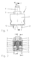
- the electrical switch 1 which can be actuated by pressure and is designed as a two-pole on-off switch and can be latched in the on and off position has a housing 2 and a base 5 which carries the electrical connections 12 4, webs 44 shown in more detail in FIG. 4 are formed with guide grooves, into which corresponding counterparts 45 engage in the interior of the housing 2.
- the housing 2 can be pushed onto the base 5 during the assembly of the switch 1 and detachably fastened to the base 5 by means of snap or snap connections known per se.
- the actuating member 4 can be moved against the pressure of a spring 6, which is located in a receptacle 7 arranged on the base 5.
- two contact bridges 8 equipped with switch contacts 10 are arranged elastically by means of springs 9.
- the switching contacts 10 of the contact bridges 8 can be brought into contact with the normally closed contact surfaces 11 of the electrical connections 12 by movement of the actuating member 4 when pressure is applied in the direction of arrow 46 (see FIG. 1), as a result of which an electrical connection between the connections 12 and thus the inputs Position of the switch 1 is made.
- the switching contacts 10 of the contact bridges 8 have a certain distance from the rest contact surfaces 11 due to the spring pressure of the spring 6, so that the electrical connection is interrupted is.
- the electrical switch 1 has a detent position in the off and in the on position.
- the locking position in the off position is determined by the fact that the actuating element 4 with the shoulders 13 rests on corresponding surfaces of the attachment 3 inside the housing 2 due to the pressure of the spring 6.
- two differently shaped guide curves 14, 15 are attached to the actuating member 4 on opposite surfaces that run parallel to the direction of movement.
- the first guide curve 14 consists of a surface 16 raised on the actuator 4, the outer contour of which is in the shape of a heart, which is why the surface 16 is also called the switching heart.
- the second guide curve 15 is formed by a surface 17 recessed on the actuating element 4, in the center of which there is an elevated, triangular surface 18, which can be seen in the comparison of FIGS. 3 and 6.
- the inner contour of the guide curve 15 is essentially heart-shaped.
- a pin 19, 20 engages in each of the two guide curves 14 and 15. These two pins 19, 20 are coupled to one another by a connecting element 21.
- the connecting element 21 has the shape of a U-shaped bracket and is inserted in a receptacle 22 on the base 5.
- the pins 19, 20 and the connecting element 21 can be produced in one piece by bending a spring wire. A round cross-section can expediently be selected for the spring wire, but any other cross-sectional shape is also conceivable.
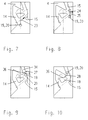
- FIGS. 7 to 13 The mode of operation of the switch 1 according to the invention is shown in more detail in FIGS. 7 to 13, in which the guide curve 15 can be seen in a top view and the guide curve 14 which is hidden on the opposite surface of the actuating member 4 is shown in dashed lines.
- the two pins 19, 20 are through Circles shown, the connecting element 21 is omitted for reasons of clarity.
- the pin 19 comes into contact with the guide curve 14, which is formed by the outer contour of the raised surface 16, and becomes corresponding to the obliquely upwardly extending outer contour deflected in the direction of arrow 23. Due to the connecting element 21, the pin 20 is deflected equally and finally, as can be seen in FIG. 8, touches the inner contour of the guide curve 15. Approximately in this position of the pins 19, 20, the switching contacts 10 of the contact bridges 8 come into contact with the normally closed contact surfaces 11 of the electrical connections (see also Fig. 2), whereby the electrical connection is made.
- the pin 19 is deflected a little further in the oblique direction 23 and finally also likewise guided vertically upwards along the outer contour of the guide curve 14 according to the arrow 25.
- the two pins 19, 20 are deflected differently due to the different shape of the two guide curves 14, 15, so that the connecting element 21 is elastically deformed in this movement section.
- the connecting element 21, which is designed as a U-shaped bracket in the present exemplary embodiment, is subjected to torsion.
- the springs 9 of the contact bridges 8 are tensioned at the same time, since the switch contacts 10 are already in contact with the normally closed contact surfaces 11.
- the two pins 19, 20 finally reach the position shown in FIG. 9. While the pin 20 is moving there in the direction of the arrow 26 into the upper channel 34, the pin 19 swings back in the direction of the arrow 27 to the deflection corresponding to the pin 20 due to the tension caused by the torsion of the U-shaped bracket , because then the forced movement by the guide curve 14 is ended.
- the downward movement of the actuator 4 is finally ended by the stop of the lower surface 35 of the actuator 4 on the base 5 (see also Fig. 5).
- the actuating member 4 is pressed again in the direction of the arrow 46 according to FIG. 1, as a result of which the pin 19 along the perpendicular upward outer contour of the guide curve 14 in the direction of the arrow 29 is performed, as can be seen in Fig. 11.
- the pin 20 is guided vertically upwards until it abuts against the inner contour of the guide curve 15 and there along obliquely upwards in the direction of the arrow 30.
- the connecting element 21 is in turn elastically deformed.
- the U-shaped bracket is subjected to torsion since the pin 20 is deflected further in the direction of the arrow 30 relative to the pin 19 guided in the vertical direction 29, as shown in FIG. 12. If the upper point 37 of the guide curve 14 is reached by the pin 19, this snaps due to the Torsional tension in the same position as the pin 20. The electrical connection is still in this position, ie the switch contacts 10 are still in contact with the normally closed contact surfaces 11. At the same time, the movement of the actuator 4 in the direction of arrow 46 in this position is again by contact the lower surface 35 terminated on the base 5.
- such a switch requires a pressure point that is clearly noticeable when it is switched on.
- This can be realized by the distance between the inner contour of the guide curve 15 and the outer contour of the triangular surface 18 at the constriction lying in the switch-on path through which the pin 20 travels from the locking position corresponding to the off position to the locking position corresponding to the on position 39, which can be seen in more detail in FIG. 6, is the same or slightly smaller than the cross-sectional width or the diameter with a round cross-section of the pin 20. If the pin 20 then reaches the constriction 39, it must be brought through the constriction 39 by means of increased pressure on the actuating element 4. After the pin 20 has passed the constriction 39, a lower pressure is again sufficient for the further movement of the actuating member 4, so that the typical pressure point behavior is present.
- the electrical connections 12 are provided with a U-shaped part 40 which is widened in relation to the connection 12, the connection 12 being bent off from one leg of the U.
- the rest contact surfaces 11 are formed by the other leg of the U's.
- the U-shaped part 40 is attached to a correspondingly shaped web 41 of the base 5. This makes it possible to attach the U-shaped part 40 in such a way that the connections 12 protrude vertically downward from the housing 2 in order to be connected to the connecting conductor tracks on a printed circuit board by means of plated-through holes.
- the U-shaped part 40 can also be plugged onto the web 41 as shown in FIG. 14 can be seen.
- connections 12 then protrude laterally at the bottom of the housing 2, which makes this switch particularly suitable for surface mounting on a printed circuit board.
- the rest contact surfaces 11 are formed by the base of the U. It should also be emphasized that there is no need for corresponding holes in the housing 2 for the implementation of the connections 12, since these protrude from the switch 1 on the base 5, which closes the housing 2 at the bottom.
- connection 42 consists of a direct extension of a leg of the U-shaped part 43, which is attached to the web 41. Connections 42 designed in this way are particularly simple to manufacture in terms of production technology. As can still be seen in FIG. 16, the connections 42 of this variant have essentially the same width as the U-shaped part 43.
- the invention is not restricted to the exemplary embodiment described. It is also within the scope of the invention to arrange the two guide curves instead of on the actuating member on the inner surfaces of the housing and the connecting element for the pins on the actuating member. It is important in the exemplary embodiment, however, that the two guide curves have a different shape, as a result of which the connecting element coupling the two pins is elastically deformed in sections during the movement of the actuating member. This elastic deformation creates a force exerted the respective pin, whereby this, as described with reference to FIGS. 7 to 13, is moved in the direction of the switching path, so that incorrect switching operations can be excluded with certainty.
Landscapes
- Push-Button Switches (AREA)
- Slide Switches (AREA)
Applications Claiming Priority (2)
| Application Number | Priority Date | Filing Date | Title |
|---|---|---|---|
| DE4202214A DE4202214A1 (de) | 1992-01-28 | 1992-01-28 | Elektrischer schalter |
| DE4202214 | 1992-01-28 |
Publications (3)
| Publication Number | Publication Date |
|---|---|
| EP0553694A2 true EP0553694A2 (fr) | 1993-08-04 |
| EP0553694A3 EP0553694A3 (fr) | 1994-01-05 |
| EP0553694B1 EP0553694B1 (fr) | 1996-04-24 |
Family
ID=6450367
Family Applications (1)
| Application Number | Title | Priority Date | Filing Date |
|---|---|---|---|
| EP93100757A Expired - Lifetime EP0553694B1 (fr) | 1992-01-28 | 1993-01-20 | Interrupteur électrique |
Country Status (5)
| Country | Link |
|---|---|
| US (1) | US5369237A (fr) |
| EP (1) | EP0553694B1 (fr) |
| JP (1) | JP2544072B2 (fr) |
| DE (2) | DE4202214A1 (fr) |
| ES (1) | ES2086794T3 (fr) |
Cited By (3)
| Publication number | Priority date | Publication date | Assignee | Title |
|---|---|---|---|---|
| FR2787627A1 (fr) * | 1998-12-18 | 2000-06-23 | Sc2N Sa | Commutateur de commande electrique de vehicule automobile |
| EP1148523A1 (fr) * | 2000-04-17 | 2001-10-24 | Sc2N | Commutateur de commande électrique de véhicule automobile |
| EP1921642A1 (fr) * | 2006-11-10 | 2008-05-14 | SAIA-Burgess Oldenburg GmbH & Co. KG | Interrupteur électrique avec au moins un boîtier |
Families Citing this family (26)
| Publication number | Priority date | Publication date | Assignee | Title |
|---|---|---|---|---|
| US5579903A (en) * | 1995-03-06 | 1996-12-03 | United Technologies Automotive, Inc. | Cam follower assembly for use in a latching switch |
| DE19544702A1 (de) * | 1995-11-30 | 1997-06-05 | Marquardt Gmbh | Elektrischer Schalter |
| DE19548600B4 (de) * | 1995-12-23 | 2006-09-28 | Marquardt Gmbh | Elektrischer Schalter |
| US5749458A (en) * | 1996-02-23 | 1998-05-12 | Auto Splice Systems, Inc. | Miniature jumper switch with wire contact maker |
| DE19603921C1 (de) * | 1996-02-03 | 1997-04-24 | Schadow Rudolf Gmbh | Druckschalter |
| US5620086A (en) * | 1996-02-23 | 1997-04-15 | Autosplice Systems, Inc. | Miniature jumper switch |
| JP2000331563A (ja) | 1999-05-24 | 2000-11-30 | Alps Electric Co Ltd | 押釦スイッチ |
| DE19960695A1 (de) * | 1999-12-16 | 2001-06-21 | Moeller Gmbh | Drucktaste für Rast- und Tastfunktion |
| TW454932U (en) * | 2000-11-07 | 2001-09-11 | Shin Chin Ind Co Ltd | Pressing button switch |
| US6552643B2 (en) * | 2000-12-11 | 2003-04-22 | Shang-Hao Chen | Structure of a depress-type safety switch |
| DE10250262A1 (de) | 2001-11-02 | 2003-05-15 | Marquardt Gmbh | Elektrischer Schalter |
| ES2190754B1 (es) * | 2001-12-21 | 2005-09-01 | Angel Iglesias, S.A | Pulsador de doble paso. |
| DE10254992B4 (de) * | 2002-11-26 | 2013-03-28 | Marquardt Gmbh | Elektrischer Schalter |
| US6737598B1 (en) | 2002-12-11 | 2004-05-18 | Tyco Electronics Canada, Ltd. | Electrical switch with limited contact arcing |
| JP4323183B2 (ja) * | 2003-02-19 | 2009-09-02 | アルプス電気株式会社 | スイッチ装置 |
| JP4167091B2 (ja) * | 2003-02-27 | 2008-10-15 | 株式会社ニフコ | スイッチ付ラッチ |
| DE10321857B4 (de) * | 2003-05-15 | 2017-03-23 | Marquardt Gmbh | Elektrischer Schalter |
| ITFI20030062U1 (it) * | 2003-06-03 | 2004-12-04 | Lucia Alfonso De | Interruttore |
| DE102006010811B4 (de) * | 2006-03-07 | 2018-03-01 | Huf Hülsbeck & Fürst Gmbh & Co. Kg | Schaltelement und Betätigungsvorrichtung damit sowie Türgriff mit dieser Betätigungsvorrichtung |
| DE102006041451B4 (de) * | 2006-09-04 | 2009-01-08 | Siemens Ag | Schaltgerät und Hilfskontaktblock zur Erweiterung eines Schaltgerätes |
| DE102009037795A1 (de) | 2008-08-26 | 2010-03-04 | Marquardt Gmbh | Elektrischer Schalter |
| CN101901704B (zh) * | 2010-06-30 | 2014-02-26 | 海洋王照明科技股份有限公司 | 一种断电保护装置及使用该断电保护装置的照明装置 |
| EP2416340A1 (fr) * | 2010-08-02 | 2012-02-08 | Eaton Industries GmbH | Dispositif de commutation doté d'un élément géométrique pour l'impact du mouvement de l'élément de contact mobile |
| DE102011110683A1 (de) | 2010-08-27 | 2012-05-03 | Marquardt Mechatronik Gmbh | Elektrischer Schalter |
| CN101980346A (zh) * | 2010-11-16 | 2011-02-23 | 张家港华峰电接插元件有限公司 | 一种按动式开关 |
| JP5727862B2 (ja) * | 2011-05-19 | 2015-06-03 | 富士電機機器制御株式会社 | 電磁接触器 |
Family Cites Families (19)
| Publication number | Priority date | Publication date | Assignee | Title |
|---|---|---|---|---|
| DE515941C (de) * | 1927-07-23 | 1931-01-15 | Carl Baer | Einrichtungen zur Herbeifuehrung abwechselnder Endstellungen bei einem entgegen demEinfluss einer Feder bewegten Betaetigungsorgan elektrischer Schalter |
| FR1223507A (fr) * | 1959-01-28 | 1960-06-17 | Arnould Ets | Perfectionnements aux interrupteurs électriques et appareils analogues |
| US3406589A (en) * | 1967-10-18 | 1968-10-22 | F & F Entpr Inc | Push-push switch structures |
| FR2133125A5 (fr) * | 1971-04-08 | 1972-11-24 | Alexander Percy | |
| US3824362A (en) * | 1973-05-23 | 1974-07-16 | Illinois Tool Works | Alternate action switch mechanism |
| US3914570A (en) * | 1973-07-05 | 1975-10-21 | Amp Inc | Alternate make and break type operating means for pushbutton switch assemblies |
| DE7408357U (de) * | 1974-03-11 | 1974-11-28 | Baer Elektrowerke Kg | Elektrischer Installationsschalter |
| CH607859A5 (en) * | 1976-05-10 | 1978-11-30 | Siemens Ag Albis | Latching device on a push-button switch having two fixed switching positions |
| FR2373863A1 (fr) * | 1976-12-08 | 1978-07-07 | Baco Sa Anct Baumgarten Const | Bouton poussoir electrique |
| FR2510808A1 (fr) * | 1981-07-29 | 1983-02-04 | Torrix Sa Ets | Interrupteur electrique a poussoir |
| US4357511A (en) * | 1981-09-04 | 1982-11-02 | Eaton Corporation | Modular push-button switch with lighted push-button element |
| JPS59181530U (ja) * | 1983-05-20 | 1984-12-04 | 市光工業株式会社 | 押釦スイツチ |
| DE3419834A1 (de) * | 1984-05-26 | 1985-11-28 | SWF Auto-Electric GmbH, 7120 Bietigheim-Bissingen | Elektrischer drucktastenschalter |
| DE3545879C2 (de) * | 1985-12-23 | 1995-11-30 | Asea Brown Boveri | Abgedichteter Drucktastenschalter, insb. in Schmalbauweise |
| DE8600788U1 (de) * | 1986-01-15 | 1987-07-02 | Rudolf Schadow GmbH, 13509 Berlin | Druck- oder Schiebetastenschalter |
| DE8616074U1 (de) * | 1986-06-14 | 1986-10-09 | Franz Kirsten Elektrotechnische Spezialfabrik, 6530 Bingen | Elektrischer Kontaktschalter |
| JPH0512892Y2 (fr) * | 1987-08-06 | 1993-04-05 | ||
| JPH0429454Y2 (fr) * | 1987-11-10 | 1992-07-16 | ||
| JPH01119132U (fr) * | 1988-02-08 | 1989-08-11 |
-
1992
- 1992-01-28 DE DE4202214A patent/DE4202214A1/de not_active Withdrawn
-
1993
- 1993-01-20 DE DE59302300T patent/DE59302300D1/de not_active Expired - Lifetime
- 1993-01-20 ES ES93100757T patent/ES2086794T3/es not_active Expired - Lifetime
- 1993-01-20 EP EP93100757A patent/EP0553694B1/fr not_active Expired - Lifetime
- 1993-01-26 JP JP5011062A patent/JP2544072B2/ja not_active Expired - Fee Related
- 1993-01-27 US US08/009,754 patent/US5369237A/en not_active Expired - Lifetime
Cited By (3)
| Publication number | Priority date | Publication date | Assignee | Title |
|---|---|---|---|---|
| FR2787627A1 (fr) * | 1998-12-18 | 2000-06-23 | Sc2N Sa | Commutateur de commande electrique de vehicule automobile |
| EP1148523A1 (fr) * | 2000-04-17 | 2001-10-24 | Sc2N | Commutateur de commande électrique de véhicule automobile |
| EP1921642A1 (fr) * | 2006-11-10 | 2008-05-14 | SAIA-Burgess Oldenburg GmbH & Co. KG | Interrupteur électrique avec au moins un boîtier |
Also Published As
| Publication number | Publication date |
|---|---|
| EP0553694B1 (fr) | 1996-04-24 |
| ES2086794T3 (es) | 1996-07-01 |
| DE4202214A1 (de) | 1993-07-29 |
| EP0553694A3 (fr) | 1994-01-05 |
| JPH0684426A (ja) | 1994-03-25 |
| US5369237A (en) | 1994-11-29 |
| JP2544072B2 (ja) | 1996-10-16 |
| DE59302300D1 (de) | 1996-05-30 |
Similar Documents
| Publication | Publication Date | Title |
|---|---|---|
| EP0553694B1 (fr) | Interrupteur électrique | |
| EP4189782B1 (fr) | Borne de connexion de conducteur | |
| DE4439008C2 (de) | Elektrischer Tastschalter | |
| DE2541922B2 (de) | Verriegelbarer Drucktastenschalter | |
| DE3900394C2 (fr) | ||
| DE3621613C2 (fr) | ||
| DE3633701C2 (fr) | ||
| EP0068483A1 (fr) | Commutateur électromécanique pour appareils téléphoniques | |
| DE60027072T2 (de) | Elektrische Steckverbindung, insbesondere für Kraftfahrzeuganwendungen | |
| DE3324253A1 (de) | Tastenschalter | |
| EP3970170A1 (fr) | Appareil de commutation doté de contacts autonettoyants | |
| DE4331445C2 (de) | Kippschalter, insbesondere für Kraftfahrzeuge | |
| WO1995033271A1 (fr) | Interrupteur a action brusque, a deplacement rectiligne du contact et systeme d'interrupteur associe | |
| DE4309132A1 (de) | Elektrischer Kontaktschalter | |
| DE102007056296B4 (de) | Kontaktvorrichtung mit Federkontakten | |
| DE19501856C1 (de) | Elektrischer Drucktastenschalter | |
| DE19614298C2 (de) | Kontaktierungsvorrichtung für ein elektrisches Installationsgerät | |
| DE2820594C2 (de) | Elektrischer Schnappschalter | |
| DE4235981A1 (de) | Elektrischer Schalter | |
| DE19600387C1 (de) | Zweistufentaster | |
| DE3607958C2 (fr) | ||
| DE2558620C2 (de) | Elektrischer Schalter | |
| DE3400502A1 (de) | Elektrisches relais | |
| DD292106A5 (de) | Geraeteeinbauschalter | |
| DE2506739C3 (de) | Herausnehmbarer Schalteinsatz für Kabelzwischenschalter |
Legal Events
| Date | Code | Title | Description |
|---|---|---|---|
| PUAI | Public reference made under article 153(3) epc to a published international application that has entered the european phase |
Free format text: ORIGINAL CODE: 0009012 |
|
| AK | Designated contracting states |
Kind code of ref document: A2 Designated state(s): DE ES FR GB IT NL SE |
|
| PUAL | Search report despatched |
Free format text: ORIGINAL CODE: 0009013 |
|
| AK | Designated contracting states |
Kind code of ref document: A3 Designated state(s): DE ES FR GB IT NL SE |
|
| 17P | Request for examination filed |
Effective date: 19940420 |
|
| 17Q | First examination report despatched |
Effective date: 19950512 |
|
| GRAH | Despatch of communication of intention to grant a patent |
Free format text: ORIGINAL CODE: EPIDOS IGRA |
|
| GRAA | (expected) grant |
Free format text: ORIGINAL CODE: 0009210 |
|
| AK | Designated contracting states |
Kind code of ref document: B1 Designated state(s): DE ES FR GB IT NL SE |
|
| PG25 | Lapsed in a contracting state [announced via postgrant information from national office to epo] |
Ref country code: NL Free format text: LAPSE BECAUSE OF FAILURE TO SUBMIT A TRANSLATION OF THE DESCRIPTION OR TO PAY THE FEE WITHIN THE PRESCRIBED TIME-LIMIT Effective date: 19960424 Ref country code: FR Effective date: 19960424 |
|
| REF | Corresponds to: |
Ref document number: 59302300 Country of ref document: DE Date of ref document: 19960530 |
|
| REG | Reference to a national code |
Ref country code: ES Ref legal event code: FG2A Ref document number: 2086794 Country of ref document: ES Kind code of ref document: T3 |
|
| ITF | It: translation for a ep patent filed | ||
| PG25 | Lapsed in a contracting state [announced via postgrant information from national office to epo] |
Ref country code: SE Effective date: 19960724 |
|
| GBT | Gb: translation of ep patent filed (gb section 77(6)(a)/1977) |
Effective date: 19960705 |
|
| EN | Fr: translation not filed | ||
| NLV1 | Nl: lapsed or annulled due to failure to fulfill the requirements of art. 29p and 29m of the patents act | ||
| PLBE | No opposition filed within time limit |
Free format text: ORIGINAL CODE: 0009261 |
|
| STAA | Information on the status of an ep patent application or granted ep patent |
Free format text: STATUS: NO OPPOSITION FILED WITHIN TIME LIMIT |
|
| 26N | No opposition filed | ||
| REG | Reference to a national code |
Ref country code: GB Ref legal event code: IF02 |
|
| PGFP | Annual fee paid to national office [announced via postgrant information from national office to epo] |
Ref country code: DE Payment date: 20120207 Year of fee payment: 20 |
|
| PGFP | Annual fee paid to national office [announced via postgrant information from national office to epo] |
Ref country code: IT Payment date: 20120126 Year of fee payment: 20 Ref country code: GB Payment date: 20120120 Year of fee payment: 20 |
|
| REG | Reference to a national code |
Ref country code: DE Ref legal event code: R071 Ref document number: 59302300 Country of ref document: DE |
|
| REG | Reference to a national code |
Ref country code: GB Ref legal event code: PE20 Expiry date: 20130119 |
|
| PG25 | Lapsed in a contracting state [announced via postgrant information from national office to epo] |
Ref country code: DE Free format text: LAPSE BECAUSE OF EXPIRATION OF PROTECTION Effective date: 20130122 Ref country code: GB Free format text: LAPSE BECAUSE OF EXPIRATION OF PROTECTION Effective date: 20130119 |
|
| PGFP | Annual fee paid to national office [announced via postgrant information from national office to epo] |
Ref country code: ES Payment date: 20120126 Year of fee payment: 20 |
|
| REG | Reference to a national code |
Ref country code: ES Ref legal event code: FD2A Effective date: 20130725 |
|
| PG25 | Lapsed in a contracting state [announced via postgrant information from national office to epo] |
Ref country code: ES Free format text: LAPSE BECAUSE OF EXPIRATION OF PROTECTION Effective date: 20130121 |