EP0554111B1 - Perfectionnements concernant des éléments filetés - Google Patents
Perfectionnements concernant des éléments filetés Download PDFInfo
- Publication number
- EP0554111B1 EP0554111B1 EP93300668A EP93300668A EP0554111B1 EP 0554111 B1 EP0554111 B1 EP 0554111B1 EP 93300668 A EP93300668 A EP 93300668A EP 93300668 A EP93300668 A EP 93300668A EP 0554111 B1 EP0554111 B1 EP 0554111B1
- Authority
- EP
- European Patent Office
- Prior art keywords
- threaded member
- ring
- threaded
- groove
- thread
- Prior art date
- Legal status (The legal status is an assumption and is not a legal conclusion. Google has not performed a legal analysis and makes no representation as to the accuracy of the status listed.)
- Expired - Lifetime
Links
Images


Classifications
-
- F—MECHANICAL ENGINEERING; LIGHTING; HEATING; WEAPONS; BLASTING
- F16—ENGINEERING ELEMENTS AND UNITS; GENERAL MEASURES FOR PRODUCING AND MAINTAINING EFFECTIVE FUNCTIONING OF MACHINES OR INSTALLATIONS; THERMAL INSULATION IN GENERAL
- F16L—PIPES; JOINTS OR FITTINGS FOR PIPES; SUPPORTS FOR PIPES, CABLES OR PROTECTIVE TUBING; MEANS FOR THERMAL INSULATION IN GENERAL
- F16L37/00—Couplings of the quick-acting type
- F16L37/08—Couplings of the quick-acting type in which the connection between abutting or axially overlapping ends is maintained by locking members
- F16L37/084—Couplings of the quick-acting type in which the connection between abutting or axially overlapping ends is maintained by locking members combined with automatic locking
- F16L37/092—Couplings of the quick-acting type in which the connection between abutting or axially overlapping ends is maintained by locking members combined with automatic locking by means of elements wedged between the pipe and the frusto-conical surface of the body of the connector
- F16L37/0925—Couplings of the quick-acting type in which the connection between abutting or axially overlapping ends is maintained by locking members combined with automatic locking by means of elements wedged between the pipe and the frusto-conical surface of the body of the connector with rings which bite into the wall of the pipe
-
- F—MECHANICAL ENGINEERING; LIGHTING; HEATING; WEAPONS; BLASTING
- F16—ENGINEERING ELEMENTS AND UNITS; GENERAL MEASURES FOR PRODUCING AND MAINTAINING EFFECTIVE FUNCTIONING OF MACHINES OR INSTALLATIONS; THERMAL INSULATION IN GENERAL
- F16L—PIPES; JOINTS OR FITTINGS FOR PIPES; SUPPORTS FOR PIPES, CABLES OR PROTECTIVE TUBING; MEANS FOR THERMAL INSULATION IN GENERAL
- F16L15/00—Screw-threaded joints; Forms of screw-threads for such joints
- F16L15/006—Screw-threaded joints; Forms of screw-threads for such joints with straight threads
- F16L15/008—Screw-threaded joints; Forms of screw-threads for such joints with straight threads with sealing rings
-
- F—MECHANICAL ENGINEERING; LIGHTING; HEATING; WEAPONS; BLASTING
- F16—ENGINEERING ELEMENTS AND UNITS; GENERAL MEASURES FOR PRODUCING AND MAINTAINING EFFECTIVE FUNCTIONING OF MACHINES OR INSTALLATIONS; THERMAL INSULATION IN GENERAL
- F16L—PIPES; JOINTS OR FITTINGS FOR PIPES; SUPPORTS FOR PIPES, CABLES OR PROTECTIVE TUBING; MEANS FOR THERMAL INSULATION IN GENERAL
- F16L37/00—Couplings of the quick-acting type
- F16L37/08—Couplings of the quick-acting type in which the connection between abutting or axially overlapping ends is maintained by locking members
- F16L37/084—Couplings of the quick-acting type in which the connection between abutting or axially overlapping ends is maintained by locking members combined with automatic locking
- F16L37/092—Couplings of the quick-acting type in which the connection between abutting or axially overlapping ends is maintained by locking members combined with automatic locking by means of elements wedged between the pipe and the frusto-conical surface of the body of the connector
- F16L37/0927—Couplings of the quick-acting type in which the connection between abutting or axially overlapping ends is maintained by locking members combined with automatic locking by means of elements wedged between the pipe and the frusto-conical surface of the body of the connector the wedge element being axially displaceable for releasing the coupling
-
- Y—GENERAL TAGGING OF NEW TECHNOLOGICAL DEVELOPMENTS; GENERAL TAGGING OF CROSS-SECTIONAL TECHNOLOGIES SPANNING OVER SEVERAL SECTIONS OF THE IPC; TECHNICAL SUBJECTS COVERED BY FORMER USPC CROSS-REFERENCE ART COLLECTIONS [XRACs] AND DIGESTS
- Y10—TECHNICAL SUBJECTS COVERED BY FORMER USPC
- Y10S—TECHNICAL SUBJECTS COVERED BY FORMER USPC CROSS-REFERENCE ART COLLECTIONS [XRACs] AND DIGESTS
- Y10S285/00—Pipe joints or couplings
- Y10S285/91—Gaskets
Definitions
- This invention relates to threaded members and in particular to the sealing of threaded members.
- the invention is particularly applicable to threaded members on tube coupling bodies for providing a sealed connection of the bodies to further threaded components.
- EP-A-0459957 discloses a tubular connector having a cylindrical screw threaded shank for engagement in a correspondingly threaded hole in a body. An annular groove is formed part-way along the threaded shank and an annular seal is located in the groove to act between the threaded shank and the threaded bore in the body. Similar arrangements are disclosed in US-A-2086133 and FR-A-1571744.
- the invention provides a threaded member having an annular groove which is of greater depth than the base of the adjacent thread, a resilient ring mounted in the groove and having an outer periphery located above the base of the thread to be deformed by the engagement of the threaded member with a corresponding threaded member to form a seal between the respective threads of the engaging members, characterised in that the resilient ring has a plurality of projections formed at spaced locations around its outer periphery comprising ribs formed integrally with the resilient ring and extending parallel to the axis of the ring across the outer face of the ring periphery, the ribs being tapered in both width and height to a point towards the entry end of the threaded member.
- the annular groove is formed part-way along the threaded member with the thread extending on either side of the groove.
- the outer periphery of the resilient ring lies just below the outer profile of the thread and the projections on the outer periphery extend above the profile of the thread.
- the ribs may be triangular in cross-section through the axis of the ring.
- the base of the annular groove containing the resilient ring may be knurled to grip with the inner face of the ring.
- the threaded member may be of parallel or tapered form.
- the threaded member may be a male member having an external thread and external annular groove in which the seal is located to engage in a corresponding internally threaded female member or may be a female member having an internal thread and internal annular groove in which the resilient seal is located to receive an externally threaded male member.
- the resilient ring may be formed from an elastomeric material and in the case where the invention is applied to an externally threaded male member is installed in the annular groove in the threaded member by stretching over the entry end of the threaded member to snap into the groove.
- the base of the groove may be undercut in one or both corners of the groove to form an encircling recess or recesses to accommodate deformation of the resilient sealing ring when said threaded members are engaged.
- the base of the groove between the undercut corners thereof has axially extending splines and the inner periphery of the resilient ring is correspondingly splined to resist rotation of the ring with respect to the threaded member when the latter is engaged with the other threaded member.
- the splines may be of trapezoidal cross section.
- the projections on the outer periphery of the ring may be tapered at both ends.
- Figure 1 of the drawings shows a tube coupling connector indicated generally at 10 comprising a body 11 machined from brass or stainless steel and having a throughway 12.
- One end 13 of the body is fitted with a moulded plastics insert sleeve 14 formed with an internal tapered cam surface 15 reducing towards the open end of the body.
- An annular collet 16 is located in the insert having resilient fingers 17 engaging the cam surface to receive a tube to be locked in the body by the collet.
- the throughway is reduced in diameter at a first step 18 where an O-ring seal 19 is located and a second step 20 with which the end of the tube to be located in the body engages.
- one end of the coupling body is adapted to receive a collet for connecting a tube in the coupling body.
- the other end of the coupling body indicated at 21 is a male form threaded member having an external parallel screw thread indicated at 22 and terminating in an end face 23.
- the coupling body is formed with a deep annular groove 24 the bottom of which lies below the bottom face of the thread indicated at 25.
- a resilient sealing ring 26 is disposed in the groove 24 formed from an elastomeric material such as a polyester.
- the outer periphery 27 of the resilient ring lies just below the outer periphery of the thread and is formed at spaced locations around the ring with four axially extending ribs 28 integral with the ring as best seen in Figures 2 and 3.
- the ribs are of generally triangular cross-section as seen in a plane containing the axis of the ring and taper both in width and height from one end 29 of the ring where they project above the adjacent thread periphery to a point 30 at the other end 31 of the ring.
- the ring is installed in the annular groove with the tapered ends of the ribs adjacent the entry end of the screw thread, that is the end adjacent end 23 of the coupling body.
- the resilient sealing ring 26 is formed as an injection moulding and is stretched and drawn over the threaded end of the coupling body to snap into the annular groove whilst still warm from its moulding operation.
- the outer periphery of the end 32 of the threaded member is bevelled as indicated at 24 to facilitate drawing the ring onto the threaded member.
- the internal diameter of the resilient ring is such that the ring grips around the base of the groove and the base may be knurled to provide a surface roughness to grip with the ring and thereby prevent the ring turning when the tube coupling body is screwed into the outer threaded component.
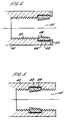
- the female member is in the form of a socket 40 having an open ended straight bore 41 formed with a parallel internal screw thread 42 to receive a threaded component to be secured in the bore.
- An annular groove 43 is formed around the open end of the bore to receive a resilient seal 44.
- the seal is held captive in the groove by an annular cover plate 45 secured to the end of the socket and overlying the adjacent end of the seal.
- the seal is formed from an elastomeric material as before and has integral upstanding axial extending ribs 46 around its inner periphery. As before, the ribs are of triangular cross-section tapering towards the open end of the bore.
- Figure 5 of the drawings shows a similar arrangement except that the groove 43 is formed part-way along the bore 41 spaced from the open end thereof. In this case of course the separate annular cover plate 45 is not required.
- the groove 24 is undercut at its corners to form recesses 24a encircling the groove to accommodate excess material of the resilient ring when it is deformed into the groove by engagement of the threaded members as described above.
- the base of the groove 24 is formed with splines 24b extending parallel to the axis of the threaded member, the splines being of truncated triangular cross-section as best seen in Figure 7.
- the resilient ring 26 has an inner periphery formed with axially extending triangular-section grooves 50 to engage with the splines and prevent the ring rotating with respect to the threaded member when the threaded member is engaged in the corresponding other threaded component.
- the ribs 28 on the outer periphery of the ring 26 are straight-cut with chamfered ends 28a (see Figure 9) to allow the ring to be engaged from either end in the other threaded member.
Landscapes
- Engineering & Computer Science (AREA)
- General Engineering & Computer Science (AREA)
- Mechanical Engineering (AREA)
- Gasket Seals (AREA)
- Non-Disconnectible Joints And Screw-Threaded Joints (AREA)
Claims (13)
- Elément fileté pourvu d'une gorge annulaire (24) qui est plus profonde que la base du filet (22) adjacent et d'un anneau élastique (26) monté dans la gorge et pourvu d'une périphérie extérieure (27) située au-dessus de la base du filet afin d'être déformée par l'engagement de l'élément fileté avec un élément fileté correspondant pour former un joint d'étanchéité entre les filets respectifs des éléments en engagement, caractérisé en ce que l'anneau élastique possède une pluralité de saillies (28) formées en des points espacés autour de sa périphérie extérieure (27) et comprenant des nervures formées d'un seul tenant avec l'anneau élastique et s'étendant parallèlement à l'axe de l'anneau sur la surface extérieure de la périphérie de l'anneau, les nervures étant rétrécies en largeur et en hauteur pour former une pointe (30) vers l'extrémité d'entrée (31) de l'élément fileté.
- Elément fileté selon la revendication 1, caractérisé en ce que la gorge annulaire (24) est formée sur une partie du trajet le long de l'élément fileté (21) avec le filet (22) de chaque côté de la gorge.
- Elément fileté selon la revendication 1 ou 2, caractérisé en ce que la périphérie extérieure de l'anneau élastique (27) se trouve juste en-dessous du profil extérieur du filet (22) et les saillies (28) de la périphérie extérieure s'étendent au-dessus du profil du filet.
- Elément fileté selon l'une ou l'ensemble des revendications 1 à 3, caractérisé en ce que les nervures (28) sont de section triangulaire à travers l'axe de l'anneau.
- Elément fileté selon l'une ou l'ensemble des revendications précédentes, caractérisé en ce que la base de la gorge annulaire (24) contenant l'anneau élastique est moletée de façon à se mettre en prise avec la face intérieure de l'anneau.
- Elément fileté selon l'une ou l'ensemble des revendications précédentes, caractérisé en ce que l'élément fileté (21) est de forme parallèle ou rétrécie.
- Elément fileté selon l'une ou l'ensemble des revendications précédentes, caractérisé en ce que l'élément (21) est un élément mâle pourvu d'un filet extérieur (22) et d'une gorge annulaire extérieure (24) dans laquelle l'anneau élastique (26) est disposé de façon à se mettre en prise dans un élément femelle à filet intérieur correspondant.
- Elément fileté selon l'une ou l'ensemble des revendications 1 à 6, caractérisé en ce que l'élément fileté (40) est un élément femelle pourvu d'un filet intérieur (42) et d'une rainure intérieure (43) dans laquelle l'anneau élastique (44) est disposé de façon à recevoir un élément mâle à filet extérieur.
- Elément fileté selon l'une ou l'ensemble des revendications précédentes, caractérisé en ce que l'anneau élastique (26, 44) est formé d'un matériau élastomère et, dans le cas où l'élément fileté est un élément mâle à filet extérieur, est installé dans la gorge annulaire de l'élément fileté en l'étirant par-dessus l'extrémité d'entrée de l'élément fileté afin de l'engager dans la gorge.
- Elément fileté selon l'une ou l'ensemble des revendications précédentes, caractérisé en ce que la base de la gorge (24) présente une contre-découpe dans l'un des coins ou les deux afin de former un ou deux évidements circulaires permettant la déformation de l'anneau d'étanchéité élastique lorsque ledits éléments filetés sont mis en prise.
- Elément fileté selon la revendication 10, caractérisé en ce que la base de la gorge (24) possède entre ses coins pourvus de contre-découpes des cannelures (24b) qui s'étendent dans le sens axial, et la périphérie intérieure de l'anneau élastique (26) est cannelée (50) de façon correspondante pour résister à la rotation de l'anneau par rapport à l'élément fileté lorsque ce dernier est engage avec l'autre élément fileté.
- Elément fileté selon la revendication 11, caractérisé en ce que les cannelures (24b) sont de forme trapézoïdale en section.
- Elément fileté selon l'une ou l'ensemble des revendications précédentes, caractérisé en ce que les saillies (28) de la périphérie extérieure de l'anneau (26) sont rétrécies aux deux extrémités (28a).
Applications Claiming Priority (4)
| Application Number | Priority Date | Filing Date | Title |
|---|---|---|---|
| GB9202044 | 1992-01-31 | ||
| GB929202044A GB9202044D0 (en) | 1992-01-31 | 1992-01-31 | Improvements in or relating to threaded members |
| GB929214334A GB9214334D0 (en) | 1992-07-06 | 1992-07-06 | Improvements in or relating to threaded members |
| GB9214334 | 1992-07-06 |
Publications (2)
| Publication Number | Publication Date |
|---|---|
| EP0554111A1 EP0554111A1 (fr) | 1993-08-04 |
| EP0554111B1 true EP0554111B1 (fr) | 1995-09-27 |
Family
ID=26300235
Family Applications (1)
| Application Number | Title | Priority Date | Filing Date |
|---|---|---|---|
| EP93300668A Expired - Lifetime EP0554111B1 (fr) | 1992-01-31 | 1993-01-29 | Perfectionnements concernant des éléments filetés |
Country Status (5)
| Country | Link |
|---|---|
| US (1) | US5375893A (fr) |
| EP (1) | EP0554111B1 (fr) |
| JP (1) | JPH06123387A (fr) |
| DE (1) | DE69300525T2 (fr) |
| ES (1) | ES2077469T3 (fr) |
Families Citing this family (15)
| Publication number | Priority date | Publication date | Assignee | Title |
|---|---|---|---|---|
| GB9325432D0 (en) * | 1993-12-13 | 1994-02-16 | Guest John D | Improvements in or relating to seal arrangements |
| DE19640251A1 (de) * | 1996-09-30 | 1998-04-02 | Ehrensperger C Ag | Vorrichtung zum Verbinden einer Montageschaumdose mit einer Pistole zum Ausbringen von Montageschaum |
| DE19906870C1 (de) * | 1999-02-18 | 2000-05-11 | Hummel Anton Verwaltung | Anschlußarmatur mit einem Armaturkörper mit drehbarer Befestigung |
| US6273478B1 (en) * | 1999-03-30 | 2001-08-14 | The Regents Of The University Of California | Microfluidic interconnects |
| US7354079B2 (en) | 2002-04-23 | 2008-04-08 | Watts Sea Tech, Inc. | Connector |
| US20050012278A1 (en) * | 2002-11-07 | 2005-01-20 | Delange Richard W. | Metal sleeve seal for threaded connections |
| US6929032B2 (en) | 2003-04-02 | 2005-08-16 | Sea Tech, Inc. | Manifold |
| US20050191122A1 (en) * | 2004-03-01 | 2005-09-01 | Gethmann Douglas P. | Locking mechanism for a threaded connection |
| US7784797B2 (en) * | 2006-05-19 | 2010-08-31 | Baker Hughes Incorporated | Seal and slip assembly for expandable downhole tools |
| AU2007300473B2 (en) * | 2006-09-22 | 2012-01-19 | Eaton Corporation | Male coupling for connecting to female threaded coupling |
| US20080143105A1 (en) * | 2006-09-22 | 2008-06-19 | Eaton Corporation | Fluid coupling |
| DE102013017499B4 (de) * | 2013-10-17 | 2018-03-29 | Kaco Gmbh + Co. Kg | Brennraumabdichtung für Verbrennungsmotoren von Fahrzeugen, vorzugsweise von Kraftfahrzeugen |
| DE102014017549A1 (de) * | 2014-11-28 | 2016-06-02 | Samson Ag | Ventilanordnung |
| US20190084203A1 (en) * | 2014-12-05 | 2019-03-21 | Elysée Piping Systems Limited | Method for embedding elastomer sealing materials on the threads of plastic fittings using two stage injection molding |
| CN107289209B (zh) * | 2017-08-22 | 2018-08-03 | 台州半城暖通科技有限公司 | 一种螺纹密封结构及其装配工艺 |
Family Cites Families (11)
| Publication number | Priority date | Publication date | Assignee | Title |
|---|---|---|---|---|
| US1100630A (en) * | 1913-04-14 | 1914-06-16 | Ferdinand L Toepperwein | Gasket or washer. |
| US1917553A (en) * | 1932-12-14 | 1933-07-11 | Albert J Scholtes | Hose union |
| US2086133A (en) * | 1935-07-24 | 1937-07-06 | Frank J Kennedy | Connection or joint |
| US2980451A (en) * | 1957-04-17 | 1961-04-18 | Atlas Pipe Inc | Threaded pipe joint having an extrudable generally non-resilient sealing means |
| CH482969A (de) * | 1967-06-14 | 1969-12-15 | Benteler Werke Ag | Mit Rechts- und Linksgewinde versehene Rohrmuffenverbindung |
| CH559872A5 (fr) * | 1972-10-11 | 1975-03-14 | Schell Hubert Kg | |
| US4085951A (en) * | 1976-10-28 | 1978-04-25 | Wonder Products Company | Hydril-type connector |
| US4088327A (en) * | 1977-06-22 | 1978-05-09 | General Signal Corporation | Sealing ring with tabs for holding for assembly |
| JPH0648075B2 (ja) * | 1990-04-16 | 1994-06-22 | エスエムシー株式会社 | 管継手 |
| IT223079Z2 (it) * | 1990-05-31 | 1995-06-09 | Camozzi Riccardo S P A | Raccordo con guarnizione di tenuta riportata sul filetto del gambo filettato |
| GB2252136A (en) * | 1991-01-24 | 1992-07-29 | Dowty Seals Ltd | A thread seal |
-
1993
- 1993-01-26 US US08/011,481 patent/US5375893A/en not_active Expired - Fee Related
- 1993-01-29 ES ES93300668T patent/ES2077469T3/es not_active Expired - Lifetime
- 1993-01-29 JP JP5013461A patent/JPH06123387A/ja active Pending
- 1993-01-29 DE DE69300525T patent/DE69300525T2/de not_active Expired - Fee Related
- 1993-01-29 EP EP93300668A patent/EP0554111B1/fr not_active Expired - Lifetime
Also Published As
| Publication number | Publication date |
|---|---|
| US5375893A (en) | 1994-12-27 |
| JPH06123387A (ja) | 1994-05-06 |
| ES2077469T3 (es) | 1995-11-16 |
| DE69300525D1 (de) | 1995-11-02 |
| EP0554111A1 (fr) | 1993-08-04 |
| DE69300525T2 (de) | 1996-05-15 |
Similar Documents
| Publication | Publication Date | Title |
|---|---|---|
| EP0554111B1 (fr) | Perfectionnements concernant des éléments filetés | |
| EP0330350B1 (fr) | Assemblages pour dispositif d'accouplement fluide | |
| US5266258A (en) | Method of sealingly seating a metal insert in a thermoplastic component | |
| US5131795A (en) | Screw threaded insert | |
| US6435568B1 (en) | Tube joint having tightening member for accommodating tubes of varying wall thickness | |
| CA1073497A (fr) | Raccord rapide | |
| EP0855546B1 (fr) | Raccord de tuyaux | |
| EP0680580B1 (fr) | Raccord venant en prise avec la surface exterieure d'un tuyau polymere | |
| US5288087A (en) | Seal for a coupling for protective tubing for electrical cables and a coupling including such a seal | |
| US4664427A (en) | Quick connect fitting | |
| US3822074A (en) | Releasable coupling for tubular members and method for assemblying said coupling | |
| EP1657480A1 (fr) | Améliorations ayant trait à des raccords de tuyauterie | |
| US5351999A (en) | Pipe coupling arrangement | |
| US20040100097A1 (en) | Tube joint | |
| KR20050062560A (ko) | 파이프용 접속 장치 | |
| US4907924A (en) | Backward starting locknut | |
| EP0425230B1 (fr) | Raccord pour tuyau | |
| US4927187A (en) | Fitting with lock wire feature | |
| EP0009368B1 (fr) | Manchon d'accouplement et raccord de tubes | |
| US4975007A (en) | Captive fastener | |
| EP0515200B1 (fr) | Presse-étoupe | |
| JP6611970B1 (ja) | ケーブルグランド | |
| US20230148293A1 (en) | Sealing insert for a corrugated-pipe screw fastening system, corrugated-pipe screw fastening system, and method for fitting a corrugated pipe | |
| US11933341B2 (en) | Threaded insert with a replaceable nut element | |
| EP0448361A1 (fr) | Perfectionnements concernant des éléments filetés |
Legal Events
| Date | Code | Title | Description |
|---|---|---|---|
| PUAI | Public reference made under article 153(3) epc to a published international application that has entered the european phase |
Free format text: ORIGINAL CODE: 0009012 |
|
| AK | Designated contracting states |
Kind code of ref document: A1 Designated state(s): DE ES FR GB IT |
|
| 17P | Request for examination filed |
Effective date: 19930818 |
|
| 17Q | First examination report despatched |
Effective date: 19941223 |
|
| GRAA | (expected) grant |
Free format text: ORIGINAL CODE: 0009210 |
|
| AK | Designated contracting states |
Kind code of ref document: B1 Designated state(s): DE ES FR GB IT |
|
| ET | Fr: translation filed | ||
| REF | Corresponds to: |
Ref document number: 69300525 Country of ref document: DE Date of ref document: 19951102 |
|
| REG | Reference to a national code |
Ref country code: ES Ref legal event code: FG2A Ref document number: 2077469 Country of ref document: ES Kind code of ref document: T3 |
|
| ITF | It: translation for a ep patent filed | ||
| PLBE | No opposition filed within time limit |
Free format text: ORIGINAL CODE: 0009261 |
|
| 26N | No opposition filed | ||
| REG | Reference to a national code |
Ref country code: GB Ref legal event code: 732E |
|
| PGFP | Annual fee paid to national office [announced via postgrant information from national office to epo] |
Ref country code: GB Payment date: 20011109 Year of fee payment: 10 |
|
| PGFP | Annual fee paid to national office [announced via postgrant information from national office to epo] |
Ref country code: FR Payment date: 20011129 Year of fee payment: 10 |
|
| REG | Reference to a national code |
Ref country code: GB Ref legal event code: IF02 |
|
| PGFP | Annual fee paid to national office [announced via postgrant information from national office to epo] |
Ref country code: ES Payment date: 20020114 Year of fee payment: 10 |
|
| PGFP | Annual fee paid to national office [announced via postgrant information from national office to epo] |
Ref country code: DE Payment date: 20020325 Year of fee payment: 10 |
|
| PG25 | Lapsed in a contracting state [announced via postgrant information from national office to epo] |
Ref country code: GB Free format text: LAPSE BECAUSE OF NON-PAYMENT OF DUE FEES Effective date: 20030129 |
|
| PG25 | Lapsed in a contracting state [announced via postgrant information from national office to epo] |
Ref country code: ES Free format text: LAPSE BECAUSE OF NON-PAYMENT OF DUE FEES Effective date: 20030130 |
|
| PG25 | Lapsed in a contracting state [announced via postgrant information from national office to epo] |
Ref country code: DE Free format text: LAPSE BECAUSE OF NON-PAYMENT OF DUE FEES Effective date: 20030801 |
|
| GBPC | Gb: european patent ceased through non-payment of renewal fee | ||
| PG25 | Lapsed in a contracting state [announced via postgrant information from national office to epo] |
Ref country code: FR Free format text: LAPSE BECAUSE OF NON-PAYMENT OF DUE FEES Effective date: 20030930 |
|
| REG | Reference to a national code |
Ref country code: FR Ref legal event code: ST |
|
| REG | Reference to a national code |
Ref country code: ES Ref legal event code: FD2A Effective date: 20030130 |
|
| PG25 | Lapsed in a contracting state [announced via postgrant information from national office to epo] |
Ref country code: IT Free format text: LAPSE BECAUSE OF NON-PAYMENT OF DUE FEES Effective date: 20050129 |
|
| REG | Reference to a national code |
Ref country code: GB Ref legal event code: 732E |