EP0554211A2 - Procédés de mesure d'une force utilisant une fibre optique - Google Patents
Procédés de mesure d'une force utilisant une fibre optique Download PDFInfo
- Publication number
- EP0554211A2 EP0554211A2 EP93810021A EP93810021A EP0554211A2 EP 0554211 A2 EP0554211 A2 EP 0554211A2 EP 93810021 A EP93810021 A EP 93810021A EP 93810021 A EP93810021 A EP 93810021A EP 0554211 A2 EP0554211 A2 EP 0554211A2
- Authority
- EP
- European Patent Office
- Prior art keywords
- birefringence
- optical waveguide
- force
- autocorrelation function
- maximum
- Prior art date
- Legal status (The legal status is an assumption and is not a legal conclusion. Google has not performed a legal analysis and makes no representation as to the accuracy of the status listed.)
- Granted
Links
Images


Classifications
-
- G—PHYSICS
- G01—MEASURING; TESTING
- G01L—MEASURING FORCE, STRESS, TORQUE, WORK, MECHANICAL POWER, MECHANICAL EFFICIENCY, OR FLUID PRESSURE
- G01L1/00—Measuring force or stress, in general
- G01L1/24—Measuring force or stress, in general by measuring variations of optical properties of material when it is stressed, e.g. by photoelastic stress analysis using infrared, visible light, ultraviolet
- G01L1/242—Measuring force or stress, in general by measuring variations of optical properties of material when it is stressed, e.g. by photoelastic stress analysis using infrared, visible light, ultraviolet the material being an optical fibre
-
- G—PHYSICS
- G01—MEASURING; TESTING
- G01L—MEASURING FORCE, STRESS, TORQUE, WORK, MECHANICAL POWER, MECHANICAL EFFICIENCY, OR FLUID PRESSURE
- G01L1/00—Measuring force or stress, in general
- G01L1/24—Measuring force or stress, in general by measuring variations of optical properties of material when it is stressed, e.g. by photoelastic stress analysis using infrared, visible light, ultraviolet
- G01L1/242—Measuring force or stress, in general by measuring variations of optical properties of material when it is stressed, e.g. by photoelastic stress analysis using infrared, visible light, ultraviolet the material being an optical fibre
- G01L1/243—Measuring force or stress, in general by measuring variations of optical properties of material when it is stressed, e.g. by photoelastic stress analysis using infrared, visible light, ultraviolet the material being an optical fibre using means for applying force perpendicular to the fibre axis
-
- G—PHYSICS
- G01—MEASURING; TESTING
- G01D—MEASURING NOT SPECIALLY ADAPTED FOR A SPECIFIC VARIABLE; ARRANGEMENTS FOR MEASURING TWO OR MORE VARIABLES NOT COVERED IN A SINGLE OTHER SUBCLASS; TARIFF METERING APPARATUS; MEASURING OR TESTING NOT OTHERWISE PROVIDED FOR
- G01D5/00—Mechanical means for transferring the output of a sensing member; Means for converting the output of a sensing member to another variable where the form or nature of the sensing member does not constrain the means for converting; Transducers not specially adapted for a specific variable
- G01D5/26—Mechanical means for transferring the output of a sensing member; Means for converting the output of a sensing member to another variable where the form or nature of the sensing member does not constrain the means for converting; Transducers not specially adapted for a specific variable characterised by optical transfer means, i.e. using infrared, visible, or ultraviolet light
- G01D5/268—Mechanical means for transferring the output of a sensing member; Means for converting the output of a sensing member to another variable where the form or nature of the sensing member does not constrain the means for converting; Transducers not specially adapted for a specific variable characterised by optical transfer means, i.e. using infrared, visible, or ultraviolet light using optical fibres
-
- G—PHYSICS
- G01—MEASURING; TESTING
- G01L—MEASURING FORCE, STRESS, TORQUE, WORK, MECHANICAL POWER, MECHANICAL EFFICIENCY, OR FLUID PRESSURE
- G01L1/00—Measuring force or stress, in general
- G01L1/24—Measuring force or stress, in general by measuring variations of optical properties of material when it is stressed, e.g. by photoelastic stress analysis using infrared, visible light, ultraviolet
- G01L1/241—Measuring force or stress, in general by measuring variations of optical properties of material when it is stressed, e.g. by photoelastic stress analysis using infrared, visible light, ultraviolet by photoelastic stress analysis
Definitions
- the invention relates to a method for fiber-optic force measurement, which is based on the voltage-induced birefringence change of a single-mode optical waveguide, which is embedded at least over a part of its length in a plane perpendicular to a prestressing force between the prestressing force across its surface, in the case of which it is clearer to achieve this Measurement results, ie for absolute measurement, polarized, non-coherent light is radiated into one end of the optical waveguide and the phase difference of the two linear modes of the two linear modes of the light waves emerging at the other end of the optical waveguide, which is caused by the force acting on the optical waveguide, is detected or compensated, and in which, if necessary, the control signal required for compensation as Measure of the force is evaluated.
- the starting point for the invention is the method for fiber-optic force measurement described in the earlier patent application P 40 37 077.1.
- a uniaxial (uniaxial) birefringence which is characterized by two refractive indices, can be induced in a fiber optic optical waveguide (LWL) by a mechanical stress field transverse to the axis of the LWL.
- the speed of propagation of the light wave thus depends on the direction of polarization.
- the extraordinary refractive index applies, perpendicular to it the ordinary one.
- the difference in the refractive indices often referred to as relative birefringence, is now a measure of the mechanical stress present.
- the direction of linearly polarized light is vectorially broken down into these two excellent, orthogonal directions and propagates at different speeds.
- the partial waves After passing through the birefringent layer, the partial waves, in particular the two linear modes, can be brought to interference using a polarizer.
- a polarizer for example a halogen lamp or a broadband light-emitting diode (LED), but with the known restriction that interference (amplitude superimposition) only occurs as long as the phase shift does not significantly exceed the coherence length of the light wave.
- the intensities add up to an average intensity which is insensitive to the change in birefringence.
- interference fringes With a continuous shift of the phase, as is possible in an interferometer, interference fringes are obtained which are amplitude-modulated with a so-called coherence function (white light interference).
- the so-called interference fringes the period of which is essentially given by the light wavelength and the spectral sensitivity of the detector used.
- the AKF has a Gaussian envelope, and the coherence length is then approximately given by the half-width X HB of the AKF.
- the relationship with the spectrum is given by an inverse Fourier transformation (theorem according to Wiener-Kintchine).
- Wiener-Kintchine The specktrum of the LED is in a very good approximation Gaussian with a coherence length of approx. 8 ⁇ m; that of the halogen lamp is not.
- the optimum of the compensation is given at the maximum of the autocorrelation.
- the object of the invention is to improve the previously known method for compensation, in particular to increase the sensitivity, if possible without using mechanically operated components.
- the basis for an economically producible measuring device is to be created at the same time, with which the forces, in particular the preload in highly loaded mechanical components, can be determined reliably and can be produced at any time.
- the phase difference caused by the action of force on the optical waveguide by a change in birefringence of the two linear modes, the light waves emerging at the other end of the optical waveguide is compensated, and in which the control signal required for the compensation is evaluated as a measure of the force
- a liquid crystal cell as the compensator element, the birefringence of which is continuously changed by the control signal is, the intensity changes which are represented as an image of the autocorrelation function (AKF) on the liquid crystal cell as a function of the control signal, and the readout signal is automatically checked for the maximum of the AKF.
- a control process for determining the associated voltage value of the control signal is determined.
- Another possibility according to the invention within the scope of the compensation method according to the invention is to determine the maximum from the determination of a plurality of intensity values lying within the coherence length by means of an algorithm suitable for determining the center of gravity.
- the fronts of the two light sources emerging with linear modes are guided transversely to the direction of propagation by an optical component with a linearly location-dependent birefringence , wherein the autocorrelation function (AKF) which forms on the light exit surface of this optical component is detected by a line detector and its readout signal sequence is evaluated in a computing process to determine the maximum of the AKF.
- AMF autocorrelation function
- a Wollaston prism, a Rochon prism, a quartz wedge or a Michelson interferometer equipped with an inclined mirroring are particularly suitable as such an optical component with linear, location-dependent birefringence.
- the first method is characterized in that it uses comparatively very simple optics can be.
- the measuring process is relatively slow overall, but this is of no importance in practice for many applications. According to the current state of development, however, the measuring range is still too limited for a desirable broad range of applications. Temperature control is also required.
- the method according to the second method according to the invention is characterized by a largely unrestricted largely linear measuring range, although it must be demanded that the light must be coupled in with high precision. Because of the very fast response behavior, a real-time measurement seems to be possible, so that the method according to the current state of development also seems to be suitable for dynamic measurements, since the compensation value can be determined simply and precisely due to the largely linear behavior with high temperature stability of the measuring arrangement.
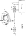
- an optical fiber 4 (see FIGS. 2 and 3), i.e. the optical fiber, is placed in a washer 3 or between two washers 3a, 3b embedded over a portion 4 'of its length.
- the washer 3 Since the FO 4 alone cannot absorb the typical pretensioning forces of, for example, 10-30 kN, distributed over a loop length of the clamped portion 4 'of, for example, 60 mm, the washer 3 has been modified so that the FO 4 can only withstand the corresponding fraction of the area must and on the other hand is protected against overloading and corrosion by a casing 5 and possibly by additional pressure-absorbing spacer rings 6a or 6b.
- a casing 5 all certain glass solders without creep or hysteresis behavior and with a thermal expansion coefficient that is matched to that of the fiber of the FO 4.
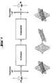
- Light from a broadband LED 10 or a halogen lamp passes through a polaristor POL1 via optical elements only indicated in the drawing and is radiated into the FO 4 at one end.
- a mechanical stress field indicated by vertical arrows induces a uniaxal birefringence in the partial region 4 ′ of the optical fiber 4, that is to say inside the washer 3, which leads to different speeds of propagation of the light wave depending on the direction of polarization.
- the light wave emerging in different modes at the other end of the optical waveguide is in turn directed via an only indicated optics known per se to a liquid crystal cell 11 as a compensating element, the birefringence of which can be changed electrically by a microprocessor control 13.
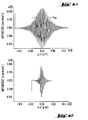
- the autocorrelation function (AKF) is observed as a function of time as a function of time through a single photodiode 12 as a function of the drive voltage at the liquid crystal cell 11.
- the maximum of the AKF is regulated by means of signal processing, which is known as the so-called “tracking method”. Another possibility for determining the maximum of the AKF consists in a scan method which is based on an algorithm which is explained below.
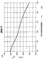
- the associated voltage that is present at the maximum of the liquid crystal cell 11 is a measure of the birefringence to be compensated for.
- the fronts of the two partial waves are guided transversely to the direction of propagation by an optical component 15 with a linearly location-dependent birefringence due to the phase differences caused by the birefringence change.
- This location coordinate can be electronically recorded with a line detector 16, for example a CCD line array, or can be fed to a processor 14 for processing.
- Such an optical component 15 can be a Wollaston prism, a Rochon prism, a quartz wedge or a modified Michelson interferometer with an inclined mirror.
- a Wollaston prism consists of two birefringent wedges 17, 18 - for example made of quartz or calcite - with optical axes that are perpendicular to the direction of propagation of the light and orthogonal to one another, for example first wedge 17 upwards second wedge 18 in the drawing plane.
- ⁇ n n e - n o (n e extraordinary and n o ordinary refractive index), ⁇ the wedge angle of the prisms and ⁇ 0 the wavelength of the light in air.
- the location of the maximum of the AKF is a measure of the birefringence present in the LWL 4 due to the mechanical stress if the phase shift is known or calibrated. If the coherence length of the light source 10 is known, then the AKF can be scaled with the experimentally determined half-width X HB of the AKF.
- the AKF can be obtained as a function of time (e.g. with FK) or a location coordinate (e.g. using Wollaston prism).
- I n is the nth intensity value, m the degree of modulation, x n the associated spatial coordinate or the nth time value, x s the value of the maximum of the AKF, x O the half-width and p the period length (pitch) of the interference fringes. If the so-called pixel spacing of the line detector 16 (of the CCD line array) is denoted by a, then x n , x s and x O can also be specified as fractions or multiples of a.
- One of the methods for determining the maximum of the AKF is the so-called focus determination .
- focus determination For a detailed description, please refer to IMT Report 286, PA 03/91.
- the constant portion or the portion that is present as a background without interference fringes eg intensity profile of the far field of the FO 4
- the interference function now oscillates symmetrically around zero, the linear centroid determination fails; you have to take the amounts or their squares, ie:
- the center of gravity coordinate is determined very precisely with a sufficient number of measuring points and is unaffected by noise signals.
- systematic sources of error have to be taken into account, which can be caused by non-plane wave fronts, by non-linearities of the Wollaston prism, by inhomogeneities of the line detector 16 and by possible errors in the force sensor 3.
- S (x n ) and C (x n ) O n arctan (S (x n ) / C (x n )) calculated and averaged over all N.
- a diode from ABB-Hafo with the type designation 1A225 was chosen as the light source 10, with which a power of a few 100 nW can be coupled into a single-mode FO 4 with a core of 6 ⁇ m diameter.
- the wavelength is 880 nm with a full half-value width of approx. 50 nm.
- the "Type S" from Reticon was used as the line detector 16, which - equipped with satellite and motherboard and 512 detector elements - has a rectangular detector area of 25 ⁇ m ⁇ x 2.5 mm.
- the Wollaston prism as optical component 15 consisted of quartz and had a location-dependent phase shift from 2 ⁇ to 0.1 mm. If the interference fringes with the CCD line array are recorded directly in contact with the Wollaston prism, there are approximately 4 pixels per interference fringes.
Landscapes
- Physics & Mathematics (AREA)
- General Physics & Mathematics (AREA)
- Investigating Or Analysing Materials By Optical Means (AREA)
- Optical Transform (AREA)
- Spinning Or Twisting Of Yarns (AREA)
- Liquid Crystal (AREA)
- Measuring Instrument Details And Bridges, And Automatic Balancing Devices (AREA)
- Inorganic Fibers (AREA)
- Yarns And Mechanical Finishing Of Yarns Or Ropes (AREA)
- Investigating Strength Of Materials By Application Of Mechanical Stress (AREA)
Applications Claiming Priority (2)
| Application Number | Priority Date | Filing Date | Title |
|---|---|---|---|
| DE4202185A DE4202185A1 (de) | 1992-01-28 | 1992-01-28 | Verfahren zur faseroptischen kraftmessung |
| DE4202185 | 1992-01-28 |
Publications (3)
| Publication Number | Publication Date |
|---|---|
| EP0554211A2 true EP0554211A2 (fr) | 1993-08-04 |
| EP0554211A3 EP0554211A3 (en) | 1993-09-15 |
| EP0554211B1 EP0554211B1 (fr) | 1994-12-14 |
Family
ID=6450348
Family Applications (1)
| Application Number | Title | Priority Date | Filing Date |
|---|---|---|---|
| EP93810021A Expired - Lifetime EP0554211B1 (fr) | 1992-01-28 | 1993-01-18 | Procédés de mesure d'une force utilisant une fibre optique |
Country Status (8)
| Country | Link |
|---|---|
| US (1) | US5317147A (fr) |
| EP (1) | EP0554211B1 (fr) |
| JP (1) | JP3220544B2 (fr) |
| KR (1) | KR100280160B1 (fr) |
| AT (1) | ATE115722T1 (fr) |
| CA (1) | CA2088095A1 (fr) |
| DE (2) | DE4202185A1 (fr) |
| ES (1) | ES2066628T3 (fr) |
Cited By (4)
| Publication number | Priority date | Publication date | Assignee | Title |
|---|---|---|---|---|
| WO1997014942A1 (fr) * | 1995-10-19 | 1997-04-24 | Alliedsignal Inc. | Detecteur polarise par birefringence |
| FR2751409A1 (fr) * | 1996-07-19 | 1998-01-23 | Univ Metz | Capteur thermo-optique de temperature utilisant le modulation electrique d'un signal optique |
| EP2202735A1 (fr) * | 2008-12-23 | 2010-06-30 | Thomson Licensing | Appareil et procédé pour la lecture et appareil pour la lecture et l'écriture d'hologrammes |
| CN113138045A (zh) * | 2021-04-28 | 2021-07-20 | 东北大学 | 一种微纳光纤阵列应力定位分析系统 |
Families Citing this family (16)
| Publication number | Priority date | Publication date | Assignee | Title |
|---|---|---|---|---|
| JPH06307953A (ja) * | 1993-04-27 | 1994-11-04 | Hitachi Ltd | 物理量検出装置 |
| US5831263A (en) * | 1994-04-26 | 1998-11-03 | Hitachi, Ltd. | In-cylinder pressure sensing apparatus for multi-cylinder engine |
| CA2122782C (fr) * | 1994-05-03 | 1999-07-27 | Wojtek J. Bock | Appareil et methode pour mesurer un parametre physique dans une fibre de detection tres birefringente |
| US5952647A (en) * | 1996-03-20 | 1999-09-14 | Seb S.A. | Force measuring apparatus with optical sensor enabling limitation of eccentricity defects in particular for bathroom scales and method of manufacturing apparatus of this kind |
| US7133134B2 (en) * | 2002-08-21 | 2006-11-07 | The Board Of Trustees Of The Leland Stanford Junior University | Method of measuring a physical function using a symmetric composite function |
| US6856393B2 (en) * | 2002-08-21 | 2005-02-15 | The Board Of Trustees Of The Leland Stanford University | Method of measuring a physical function using a composite function which includes the physical function and an arbitrary reference function |
| US7259868B2 (en) * | 2003-11-25 | 2007-08-21 | The Board Of Trustees Of The Leland Stanford Junior University | Method for determining the optical nonlinearity profile of a material |
| US7440087B2 (en) * | 2004-02-24 | 2008-10-21 | Luna Innovations Incorporated | Identifying optical fiber segments and determining characteristics of an optical device under test based on fiber segment scatter pattern data |
| US7772541B2 (en) * | 2004-07-16 | 2010-08-10 | Luna Innnovations Incorporated | Fiber optic position and/or shape sensing based on rayleigh scatter |
| US7781724B2 (en) * | 2004-07-16 | 2010-08-24 | Luna Innovations Incorporated | Fiber optic position and shape sensing device and method relating thereto |
| US7330245B2 (en) * | 2005-03-10 | 2008-02-12 | Luna Innovations Incorporated | Calculation of birefringence in a waveguide based on Rayleigh scatter |
| EP2035792B1 (fr) * | 2006-06-16 | 2018-05-23 | Intuitive Surgical Operations, Inc. | Discrimination de l'effort et de la temperature distribues dans une fibre a maintien de la polarisation |
| US7688430B2 (en) * | 2007-12-10 | 2010-03-30 | At&T Intellectual Property I, L.P. | Method and apparatus for measuring the birefringence autocorrelation length in optical fibers |
| JP5369734B2 (ja) * | 2009-02-10 | 2013-12-18 | 三菱電機株式会社 | 方位探知装置及び方位探知方法 |
| US8215177B2 (en) * | 2009-11-16 | 2012-07-10 | Freescale Semiconductor, Inc. | Apparatus and methods for applying stress-induced offset compensation in sensor devices |
| WO2014066826A1 (fr) | 2012-10-25 | 2014-05-01 | Colorado State University Research Foundation | Capteur optique multi-analyte amélioré |
Family Cites Families (8)
| Publication number | Priority date | Publication date | Assignee | Title |
|---|---|---|---|---|
| DE2845625A1 (de) * | 1978-10-19 | 1980-04-30 | Siemens Ag | Anordnung zur elektrooptischen spannungsmessung |
| US4269511A (en) * | 1979-02-15 | 1981-05-26 | Abbott Laboratories | Apparatus and method for measuring the magnitude of polarization of light |
| US4516021A (en) * | 1982-08-09 | 1985-05-07 | Taylor Henry F | Fiber optic magnetic field sensor |
| CH661985A5 (de) * | 1984-01-24 | 1987-08-31 | Mettler Instrumente Ag | Verfahren zur kraftmessung mit hilfe der spannungsinduzierten doppelbrechung in einem monomode-lichtleiter und messanordnung zur durchfuehrung des verfahrens. |
| DE3611119C1 (de) * | 1986-04-03 | 1987-07-02 | Fraunhofer Ges Forschung | Sensoranordnung |
| JP2571385B2 (ja) * | 1987-05-31 | 1997-01-16 | 浜松ホトニクス株式会社 | 電圧検出装置 |
| FR2656095B1 (fr) * | 1989-12-19 | 1994-12-23 | Thomson Csf | Capteur a fibre optique. |
| DE4037077A1 (de) | 1990-11-22 | 1992-05-27 | Hilti Ag | Verfahren und einrichtung zur faseroptischen kraftmessung |
-
1992
- 1992-01-28 DE DE4202185A patent/DE4202185A1/de not_active Withdrawn
-
1993
- 1993-01-18 AT AT93810021T patent/ATE115722T1/de not_active IP Right Cessation
- 1993-01-18 ES ES93810021T patent/ES2066628T3/es not_active Expired - Lifetime
- 1993-01-18 EP EP93810021A patent/EP0554211B1/fr not_active Expired - Lifetime
- 1993-01-18 DE DE59300038T patent/DE59300038D1/de not_active Expired - Fee Related
- 1993-01-26 CA CA002088095A patent/CA2088095A1/fr not_active Abandoned
- 1993-01-26 US US08/008,927 patent/US5317147A/en not_active Expired - Fee Related
- 1993-01-26 KR KR1019930000916A patent/KR100280160B1/ko not_active Expired - Fee Related
- 1993-01-28 JP JP01271493A patent/JP3220544B2/ja not_active Expired - Fee Related
Cited By (6)
| Publication number | Priority date | Publication date | Assignee | Title |
|---|---|---|---|---|
| WO1997014942A1 (fr) * | 1995-10-19 | 1997-04-24 | Alliedsignal Inc. | Detecteur polarise par birefringence |
| US5694205A (en) * | 1995-10-19 | 1997-12-02 | Alliedsignal Inc. | Birefringent-biased sensor having temperature compensation |
| FR2751409A1 (fr) * | 1996-07-19 | 1998-01-23 | Univ Metz | Capteur thermo-optique de temperature utilisant le modulation electrique d'un signal optique |
| EP2202735A1 (fr) * | 2008-12-23 | 2010-06-30 | Thomson Licensing | Appareil et procédé pour la lecture et appareil pour la lecture et l'écriture d'hologrammes |
| US8437060B2 (en) | 2008-12-23 | 2013-05-07 | Thomson Licensing | Apparatus and method for reading and apparatus for reading and writing holograms |
| CN113138045A (zh) * | 2021-04-28 | 2021-07-20 | 东北大学 | 一种微纳光纤阵列应力定位分析系统 |
Also Published As
| Publication number | Publication date |
|---|---|
| JPH0611399A (ja) | 1994-01-21 |
| EP0554211A3 (en) | 1993-09-15 |
| DE4202185A1 (de) | 1993-07-29 |
| CA2088095A1 (fr) | 1993-07-29 |
| JP3220544B2 (ja) | 2001-10-22 |
| ES2066628T3 (es) | 1995-03-01 |
| KR100280160B1 (ko) | 2001-11-22 |
| US5317147A (en) | 1994-05-31 |
| KR930016767A (ko) | 1993-08-30 |
| EP0554211B1 (fr) | 1994-12-14 |
| DE59300038D1 (de) | 1995-01-26 |
| ATE115722T1 (de) | 1994-12-15 |
Similar Documents
| Publication | Publication Date | Title |
|---|---|---|
| EP0554211B1 (fr) | Procédés de mesure d'une force utilisant une fibre optique | |
| EP0487450B1 (fr) | Procédés et dispositifs de mesure de force à fibre optique | |
| DE69521971T2 (de) | Optisches Mikrosystem des Typs Rosettenspannungslehre mit dielektrischen Leitern zur Messung der longitudinalen Spannung in Planarstruktur | |
| DE3138075C2 (fr) | ||
| DE3486178T2 (de) | Optisches Instrument zur Messung einer Verschiebung. | |
| DE4201511C5 (de) | Positionsdetektor und Verfahren zur Positionsmessung | |
| DE3781837T2 (de) | Interferometer zur winkelmessung. | |
| DE3715693C1 (de) | Flaechiger,taktiler Sensor | |
| DE3049033C2 (fr) | ||
| EP0316619B1 (fr) | Capteur à fibre optique | |
| EP0561015A1 (fr) | Mesure de phase interferométrique | |
| EP2856096B1 (fr) | Système optique de mesure avec compensation de polarisation et une méthode correspondante | |
| DE69414750T2 (de) | Photodetektor und Verfahren zum Empfangen optischer Signale unbekannter Polarisation | |
| DE69217246T2 (de) | Doppelbrechender temperaturfühler | |
| EP0393382B1 (fr) | Dispositif pour mesurer un champ électrique | |
| DE60202137T2 (de) | Stabilisiertes Fabry-Perot Interferometer und Verfahren zum Stabilisieren eines Fabry-Perot Interferometers | |
| DE3929340A1 (de) | Integriert-optischer sensor | |
| DE69003002T2 (de) | Druckwandler mit optischer Faser. | |
| EP0356670B1 (fr) | Sonde de courant à fibre optique | |
| DE69016720T2 (de) | Optischer Sensor mit Modeninterferenzmessung. | |
| DE3611119C1 (de) | Sensoranordnung | |
| DE69317874T2 (de) | Verfahren und vorrichtung zur differentiellen messung von brechungsindizes und deren anwendung | |
| DE3884489T2 (de) | Spannungsdetektor. | |
| DE112012002258B4 (de) | Faseroptischer Spannungssensor | |
| EP1368667B1 (fr) | Procede et dispositif de mesure de courant au moyen d'un interferometre de sagnac en ligne a fibres optiques et modulateur de phase approprie |
Legal Events
| Date | Code | Title | Description |
|---|---|---|---|
| PUAI | Public reference made under article 153(3) epc to a published international application that has entered the european phase |
Free format text: ORIGINAL CODE: 0009012 |
|
| PUAL | Search report despatched |
Free format text: ORIGINAL CODE: 0009013 |
|
| AK | Designated contracting states |
Kind code of ref document: A2 Designated state(s): AT BE CH DE ES FR GB IT LI |
|
| AK | Designated contracting states |
Kind code of ref document: A3 Designated state(s): AT BE CH DE ES FR GB IT LI |
|
| 17P | Request for examination filed |
Effective date: 19931001 |
|
| 17Q | First examination report despatched |
Effective date: 19940516 |
|
| GRAA | (expected) grant |
Free format text: ORIGINAL CODE: 0009210 |
|
| ITF | It: translation for a ep patent filed | ||
| AK | Designated contracting states |
Kind code of ref document: B1 Designated state(s): AT BE CH DE ES FR GB IT LI |
|
| REF | Corresponds to: |
Ref document number: 115722 Country of ref document: AT Date of ref document: 19941215 Kind code of ref document: T |
|
| PGFP | Annual fee paid to national office [announced via postgrant information from national office to epo] |
Ref country code: AT Payment date: 19950126 Year of fee payment: 3 |
|
| REF | Corresponds to: |
Ref document number: 59300038 Country of ref document: DE Date of ref document: 19950126 |
|
| ET | Fr: translation filed | ||
| REG | Reference to a national code |
Ref country code: ES Ref legal event code: FG2A Ref document number: 2066628 Country of ref document: ES Kind code of ref document: T3 |
|
| GBT | Gb: translation of ep patent filed (gb section 77(6)(a)/1977) |
Effective date: 19950223 |
|
| PGFP | Annual fee paid to national office [announced via postgrant information from national office to epo] |
Ref country code: CH Payment date: 19950412 Year of fee payment: 3 |
|
| PLBE | No opposition filed within time limit |
Free format text: ORIGINAL CODE: 0009261 |
|
| STAA | Information on the status of an ep patent application or granted ep patent |
Free format text: STATUS: NO OPPOSITION FILED WITHIN TIME LIMIT |
|
| 26N | No opposition filed | ||
| PG25 | Lapsed in a contracting state [announced via postgrant information from national office to epo] |
Ref country code: AT Effective date: 19960118 |
|
| PG25 | Lapsed in a contracting state [announced via postgrant information from national office to epo] |
Ref country code: LI Effective date: 19960131 Ref country code: CH Effective date: 19960131 |
|
| REG | Reference to a national code |
Ref country code: CH Ref legal event code: PL |
|
| PGFP | Annual fee paid to national office [announced via postgrant information from national office to epo] |
Ref country code: FR Payment date: 19961128 Year of fee payment: 5 |
|
| PGFP | Annual fee paid to national office [announced via postgrant information from national office to epo] |
Ref country code: GB Payment date: 19970108 Year of fee payment: 5 |
|
| PGFP | Annual fee paid to national office [announced via postgrant information from national office to epo] |
Ref country code: ES Payment date: 19970113 Year of fee payment: 5 |
|
| PG25 | Lapsed in a contracting state [announced via postgrant information from national office to epo] |
Ref country code: GB Free format text: LAPSE BECAUSE OF NON-PAYMENT OF DUE FEES Effective date: 19980118 |
|
| PG25 | Lapsed in a contracting state [announced via postgrant information from national office to epo] |
Ref country code: ES Free format text: LAPSE BECAUSE OF NON-PAYMENT OF DUE FEES Effective date: 19980119 |
|
| PG25 | Lapsed in a contracting state [announced via postgrant information from national office to epo] |
Ref country code: FR Free format text: THE PATENT HAS BEEN ANNULLED BY A DECISION OF A NATIONAL AUTHORITY Effective date: 19980131 |
|
| GBPC | Gb: european patent ceased through non-payment of renewal fee |
Effective date: 19980118 |
|
| REG | Reference to a national code |
Ref country code: FR Ref legal event code: ST |
|
| PGFP | Annual fee paid to national office [announced via postgrant information from national office to epo] |
Ref country code: BE Payment date: 20000315 Year of fee payment: 8 |
|
| REG | Reference to a national code |
Ref country code: ES Ref legal event code: FD2A Effective date: 20000403 |
|
| PG25 | Lapsed in a contracting state [announced via postgrant information from national office to epo] |
Ref country code: BE Free format text: LAPSE BECAUSE OF NON-PAYMENT OF DUE FEES Effective date: 20010131 |
|
| BERE | Be: lapsed |
Owner name: HILTI A.G. Effective date: 20010131 |
|
| PG25 | Lapsed in a contracting state [announced via postgrant information from national office to epo] |
Ref country code: IT Free format text: LAPSE BECAUSE OF NON-PAYMENT OF DUE FEES;WARNING: LAPSES OF ITALIAN PATENTS WITH EFFECTIVE DATE BEFORE 2007 MAY HAVE OCCURRED AT ANY TIME BEFORE 2007. THE CORRECT EFFECTIVE DATE MAY BE DIFFERENT FROM THE ONE RECORDED. Effective date: 20050118 |
|
| PGFP | Annual fee paid to national office [announced via postgrant information from national office to epo] |
Ref country code: DE Payment date: 20051222 Year of fee payment: 14 |
|
| PG25 | Lapsed in a contracting state [announced via postgrant information from national office to epo] |
Ref country code: DE Free format text: LAPSE BECAUSE OF NON-PAYMENT OF DUE FEES Effective date: 20070801 |