EP0554473A1 - Klammer, insbesondere zur Befestigung von Heizkörpern - Google Patents
Klammer, insbesondere zur Befestigung von Heizkörpern Download PDFInfo
- Publication number
- EP0554473A1 EP0554473A1 EP92101723A EP92101723A EP0554473A1 EP 0554473 A1 EP0554473 A1 EP 0554473A1 EP 92101723 A EP92101723 A EP 92101723A EP 92101723 A EP92101723 A EP 92101723A EP 0554473 A1 EP0554473 A1 EP 0554473A1
- Authority
- EP
- European Patent Office
- Prior art keywords
- clamp according
- clamp
- hooked
- jaw
- slot
- Prior art date
- Legal status (The legal status is an assumption and is not a legal conclusion. Google has not performed a legal analysis and makes no representation as to the accuracy of the status listed.)
- Granted
Links
- 125000006850 spacer group Chemical group 0.000 claims description 2
- 239000000463 material Substances 0.000 description 3
- 230000002093 peripheral effect Effects 0.000 description 3
- 239000004568 cement Substances 0.000 description 1
- 238000002347 injection Methods 0.000 description 1
- 239000007924 injection Substances 0.000 description 1
- 239000002184 metal Substances 0.000 description 1
- 239000004033 plastic Substances 0.000 description 1
- 229920003023 plastic Polymers 0.000 description 1
- 230000001681 protective effect Effects 0.000 description 1
- 238000007493 shaping process Methods 0.000 description 1
- 239000007787 solid Substances 0.000 description 1
- 239000002023 wood Substances 0.000 description 1
Images


Classifications
-
- F—MECHANICAL ENGINEERING; LIGHTING; HEATING; WEAPONS; BLASTING
- F24—HEATING; RANGES; VENTILATING
- F24D—DOMESTIC- OR SPACE-HEATING SYSTEMS, e.g. CENTRAL HEATING SYSTEMS; DOMESTIC HOT-WATER SUPPLY SYSTEMS; ELEMENTS OR COMPONENTS THEREFOR
- F24D19/00—Details
- F24D19/02—Arrangement of mountings or supports for radiators
- F24D19/024—Functioning details of supporting means for radiators
- F24D19/0243—Means for moving the radiator horizontally to adjust the radiator position
-
- F—MECHANICAL ENGINEERING; LIGHTING; HEATING; WEAPONS; BLASTING
- F24—HEATING; RANGES; VENTILATING
- F24D—DOMESTIC- OR SPACE-HEATING SYSTEMS, e.g. CENTRAL HEATING SYSTEMS; DOMESTIC HOT-WATER SUPPLY SYSTEMS; ELEMENTS OR COMPONENTS THEREFOR
- F24D19/00—Details
- F24D19/02—Arrangement of mountings or supports for radiators
-
- F—MECHANICAL ENGINEERING; LIGHTING; HEATING; WEAPONS; BLASTING
- F24—HEATING; RANGES; VENTILATING
- F24D—DOMESTIC- OR SPACE-HEATING SYSTEMS, e.g. CENTRAL HEATING SYSTEMS; DOMESTIC HOT-WATER SUPPLY SYSTEMS; ELEMENTS OR COMPONENTS THEREFOR
- F24D19/00—Details
- F24D19/02—Arrangement of mountings or supports for radiators
- F24D19/0203—Types of supporting means
- F24D19/0209—Supporting means having bracket
-
- F—MECHANICAL ENGINEERING; LIGHTING; HEATING; WEAPONS; BLASTING
- F24—HEATING; RANGES; VENTILATING
- F24D—DOMESTIC- OR SPACE-HEATING SYSTEMS, e.g. CENTRAL HEATING SYSTEMS; DOMESTIC HOT-WATER SUPPLY SYSTEMS; ELEMENTS OR COMPONENTS THEREFOR
- F24D19/00—Details
- F24D19/02—Arrangement of mountings or supports for radiators
- F24D19/024—Functioning details of supporting means for radiators
- F24D19/0246—Means for moving the radiator vertically to adjust the radiator position
-
- F—MECHANICAL ENGINEERING; LIGHTING; HEATING; WEAPONS; BLASTING
- F24—HEATING; RANGES; VENTILATING
- F24D—DOMESTIC- OR SPACE-HEATING SYSTEMS, e.g. CENTRAL HEATING SYSTEMS; DOMESTIC HOT-WATER SUPPLY SYSTEMS; ELEMENTS OR COMPONENTS THEREFOR
- F24D19/00—Details
- F24D19/02—Arrangement of mountings or supports for radiators
- F24D19/024—Functioning details of supporting means for radiators
- F24D19/025—Eccentric means for moving the radiator vertically
-
- F—MECHANICAL ENGINEERING; LIGHTING; HEATING; WEAPONS; BLASTING
- F24—HEATING; RANGES; VENTILATING
- F24D—DOMESTIC- OR SPACE-HEATING SYSTEMS, e.g. CENTRAL HEATING SYSTEMS; DOMESTIC HOT-WATER SUPPLY SYSTEMS; ELEMENTS OR COMPONENTS THEREFOR
- F24D19/00—Details
- F24D19/02—Arrangement of mountings or supports for radiators
- F24D19/024—Functioning details of supporting means for radiators
- F24D19/0256—Radiators clamped by supporting means
- F24D19/0259—Radiators clamped by supporting means around a column or tube
-
- F—MECHANICAL ENGINEERING; LIGHTING; HEATING; WEAPONS; BLASTING
- F24—HEATING; RANGES; VENTILATING
- F24D—DOMESTIC- OR SPACE-HEATING SYSTEMS, e.g. CENTRAL HEATING SYSTEMS; DOMESTIC HOT-WATER SUPPLY SYSTEMS; ELEMENTS OR COMPONENTS THEREFOR
- F24D19/00—Details
- F24D19/02—Arrangement of mountings or supports for radiators
- F24D19/024—Functioning details of supporting means for radiators
-
- F—MECHANICAL ENGINEERING; LIGHTING; HEATING; WEAPONS; BLASTING
- F24—HEATING; RANGES; VENTILATING
- F24D—DOMESTIC- OR SPACE-HEATING SYSTEMS, e.g. CENTRAL HEATING SYSTEMS; DOMESTIC HOT-WATER SUPPLY SYSTEMS; ELEMENTS OR COMPONENTS THEREFOR
- F24D2220/00—Components of central heating installations excluding heat sources
- F24D2220/20—Heat consumers
- F24D2220/2009—Radiators
- F24D2220/2018—Column radiators having vertically extending tubes
-
- F—MECHANICAL ENGINEERING; LIGHTING; HEATING; WEAPONS; BLASTING
- F24—HEATING; RANGES; VENTILATING
- F24D—DOMESTIC- OR SPACE-HEATING SYSTEMS, e.g. CENTRAL HEATING SYSTEMS; DOMESTIC HOT-WATER SUPPLY SYSTEMS; ELEMENTS OR COMPONENTS THEREFOR
- F24D2220/00—Components of central heating installations excluding heat sources
- F24D2220/20—Heat consumers
- F24D2220/2009—Radiators
- F24D2220/2045—Radiators having horizontally extending tubes
Definitions
- the present invention relates to a clamp, particularly for supporting radiators.
- hook-shaped clamps are currently used to support radiators and have several disadvantages such as the difficulty of fixing them to the wall of the building and the impossibility of adjusting their positions.
- the fixing of these clamps to the wall in fact requires the forming of a hole in the wall and the fixing of one end of the clamp in this hole by means of the injection of a quick-setting cement. Since at least two clamps are needed to support the radiator, it is clear that, with this type of attachment, it is impossible to adjust the relative positions of the clamps and hence that of the radiator to the wall correctly. Moreover it is also difficult to adjust the depth of fixing of the hooks and, hence, the distance of the radiator from the wall of the building for the same reasons. Finally it must be stressed that the hook-shaped clamps are not aesthetically pleasing which is in complete contrast to the current mode of operation of radiator manufacturers who are seeking to produce highly aesthetic radiators such as almost to be pieces of furniture in themselves.
- the object of the present invention is to provide a clamp which does not have the aforesaid disadvantages and which is easy to fix to the wall and is provided with systems for the adjustment of its position.
- a clamp particularly for supporting radiators, characterised in that it includes: a first body fixed to a fixed structure; a second body with the same longitudinal axis as the first body and fixed thereto; and a vice for clamping a bar of the radiator, defined by a first hooked jaw carried by the second body and a second hooked jaw which is to clamp the said bar against the first hooked jaw.
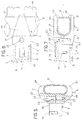
- a clamp generally indicated 1 is fixed to a wall 2 of a building to enable the support of a bar member such as, for example, a radiator.
- the clamp 1 has a system for adjusting its position relative to the wall 2 and a system for adjusting its longitudinal extension.
- the clamp 1 includes a first body 3 for fixing to the wall 2, a second body 4 intended to be connected mechanically at one end to the body 3 and at the other end having a vice 5 which will clamp a cylindrical bar 6 of the radiator.
- the body 3 is cup-shaped and has four side walls 7 arranged in two parallel pairs and a base wall 8 which, in use, faces the wall 2.
- the wall 8 has a central through-slot 11 through which the threaded shank of a screw 12 may project into an expansion plug 13 arranged in the wall 2.
- the longitudinal axis of the slot 11 lies in a plane parallel to that defined by the face of the wall 2 whereby, by arranging this axis of the slot 11 in line with one of the two cartesian axes definable on the wall 2, it is possible to adjust the position of the body 3 along the selected cartesian axis.
- the central part of one side wall 7 is formed with a through slot 14 with its longitudinal axis parallel to the longitudinal axis of the body 3.
- the body 4 includes a prismatic portion 15 which, in use, will be housed coaxially within the body 3.
- the portion 15 is formed with a threaded hole 16 perpendicular to the longitudinal axis of the portion 15 itself and in line with the slot 14.
- a screw 17 passes through the slot 14 and, when screwed into the hole 16, fixes the bodies 3 and 4 together mechanically.
- the vice 5 is constituted by two hooked jaws 18 and 21 of which the jaw 18 is formed integrally with the portion 15 and the jaw 21 is fixed to the jaw 18 by a screw 22.
- the jaws 18 and 21 have the same geometric conformation and, in particular, they include a thicker portion 23 by which the jaws 18 and 21 are fixed together, and a thinner portion 24 which clamps the bar 6.
- the portion 23 of the jaw 18 projects from an end face of the portion 15 or preferably, from a lower region of this face.
- the jaws 18 and 21 have substantially constant widths along their longitudinal axes, this width being substantially equal to that of the body 3.
- the faces of the jaws 18 and 21 which face each other have a first part, defined by the portion 23, which lies in a plane perpendicular to the said end face of the portion 15, and a second part, defined by the portion 24, which describes a semi-cylindrical surface.
- the shape of the second part of these faces of the jaws 18 and 21 enables the vice 5 to define a clamping surface which is almost completely cylindrical and of a diameter substantially equal to the external diameter of the bar 6.
- the flat face of the portion 23 of the jaw 18 is formed with a threaded blind hole 25 coaxial with a through hole 26 in the portion 23 of the jaw 21.
- the screw 22 passes through the hole 26 and is screwed into the hole 25 until its head comes to bear against a shoulder 27 formed in the hole 26.
- the flat face of the jaw 21 fits against the corresponding flat face of the jaw 18 just as the end face of the portion 23 of the jaw 21 fits against the upper part of the end face of the portion 15.
- each body 3 is then made in the wall 2 and the plug 13 is then placed in it. Subsequently the screw 12 is screwed in to a minimum extent so that the position of each body 3 relative to the wall 2 and to the other bodies 3 can be adjusted, taking account of the fact that several clamps 1 are used to support a radiator.
- the bar 6 is then clamped in the vice 5 by the initial placing of the bar 6 on the hooked jaw 18 and the subsequent fixing of the jaw 21 to the latter. Finally, the radiator being raised, each portion 15 is introduced into the corresponding body 3. It is now possible first to adjust the axial position of the body 4 relative to the body 3 and then to fix the two together by the screw 17.
- the radiator may be fixed to a vertical wall, parallel thereto, or simultaneously to the vertical wall and to the floor like a flag.
- first case depending on the vertical or horizontal disposition of the longitudinal axis of the slot 11, either the height of the clamp 1 relative to the floor or the distance between two clamps 1 at the same level can be determined by the adjustment of the body 3.
- second case in which the clamps are disposed on the floor, depending on the disposition of the axis of the slot 11 along two horizontal cartesian axes, either the distance of the clamps 1 from each other and from an edge of the floor or the perpendicularity of the axis along which the clamps 1 are fixed relative to the vertical wall can be determined by the adjusttment of the body 3.
- the adjustment of the axial position of the body 4 relative to the body 3 enables the distance of the radiator from the wall 2 to be determined.
- the clamp 1 includes a spacer member 31 having a portion 32 of smaller longitudinal extent similar to the portion 15 in that it is introduced into the body 3, and a hollow portion 33 of larger longitudinal extent similar to the body 3 in that it accepts the portion 15 of the body 4 within it.
- the portion 32 is formed with a threaded blind hole 34 into which the screw 17 is screwed and thus fixes the member 31 to the body 3.
- a side wall of the portion 33 is formed with a hole 35 through which a screw 36 may be screwed into the hole 16 so as to fix the body 4 to the member 31.
- a body 4 which differs from that illustrated in Figure 1 in the different internal conformation of the vice 5 because of the different peripheral profile of the section of the bar 6.
- This in fact has a section with a substantially elliptical profile whereby, in order to achieve the proper clamping thereof, the inner faces of the hooked jaws 18 and 21 of the vice 5 together define a semi-elliptical surface.
- a clamp 1 which is adapted to support a radiator having a bar 6 with a semi-ovoidal profile in section and having bars 41 which project perpendicularly from the bar 6 and which are a short distance apart.
- the bar 6 has a rectangular section with two longer straight sides, a shorter straight side outside the vice 5 and a shorter side within the vice 5 which is formed as an arc of a circle.
- the inner faces of the portions 24 of the jaws 18 and 21 have a first semi-circular zone which will mate with a part of the said circular side and a second straight zone which will mate with the corresponding longer straight side of the section of the bar 6.
- each portion 24 has a free end 42 which is turned inwardly at right angles so as to embrace the bar 6 almost completely by fitting over a respective part of the shorter straight side of the section of the bar 6. Since the distance between the bars 41 is less than the width of the portions 24, these differ from those illustrated in Figure 1 in that they taper in width so that the said ends 42 can be disposed between the bars 41.
- the clamps 1 it is possible to adjust not only the position of the radiator relative to the wall 2 but also its distance from the latter and these adjustments are easy to carry out. Moreover the clamps 1 are quick and easy to fix to the wall 2 since the fixing not involve complicated operations to be carried out on the latter, the positioning of an expansion plug being sufficient.
- the body 3 of the clamp 1 remaining fixed, it may present a body 4 with a vice adapted, by its shape, to clamp bars 6 of different sections.
- the clamp 1 may be arranged, by means of the member 31, to support radiators at great distances from the wall 2. It should be stressed that the structural simplicity of the clamp 1 makes it cheap to produce. Finally, it may be stated that, compared with clamps currently in use, the clamp 1 is aesthetically pleasing since the various fixing screws are hidden in the corresponding slots or holes.
- the clamp 1 may also be used for supporting objects other than radiators but, naturally, having a bar (whether solid or hollow) forming part of the structure of the object or defining it.
- the clamp 1 could be fixed to any fixed structure.
- the bar 6 may have a peripheral profile different from those described and illustrated.
- the body 3 may have several slots 14 in the same wall 7 or in different walls 7, just as the portion 15 may have several holes 16 in the same face or in different faces; thus it is possible to modify the relative angular positions of the bodies 3 and 4.
- the portion 15 of the body 4 could also be hollow in order to achieve a saving in material.
- the shape of the body 3 and of the portion 15 for example so that the portion 15 receives the body 3 within it; naturally, in this case, the slot 14 would be formed in one face of the portion 15 and the hole 16 would be formed in a wall 7 of the body 3. It is clear that the peripheral development of the body 3 and of the portion 15 illustrated are not limiting in that it is possible to define a different shape, for example cylindrical, therewith.
- the clamp 1 is preferably made of metal but the use of different materials, such as wood or plastics material for supporting less heavy objects is not excluded.
Landscapes
- Engineering & Computer Science (AREA)
- Physics & Mathematics (AREA)
- Thermal Sciences (AREA)
- Chemical & Material Sciences (AREA)
- Combustion & Propulsion (AREA)
- Mechanical Engineering (AREA)
- General Engineering & Computer Science (AREA)
- Clamps And Clips (AREA)
- Connection Of Plates (AREA)
- Cooling, Air Intake And Gas Exhaust, And Fuel Tank Arrangements In Propulsion Units (AREA)
- Details Of Heat-Exchange And Heat-Transfer (AREA)
Applications Claiming Priority (2)
| Application Number | Priority Date | Filing Date | Title |
|---|---|---|---|
| ITBO910053U | 1991-03-18 | ||
| ITBO910053U IT224109Z2 (it) | 1991-03-18 | 1991-03-18 | Gancio in particolare per il supporto di radiatori. |
Publications (3)
| Publication Number | Publication Date |
|---|---|
| EP0554473A1 true EP0554473A1 (de) | 1993-08-11 |
| EP0554473B1 EP0554473B1 (de) | 1996-05-15 |
| EP0554473B2 EP0554473B2 (de) | 1999-01-27 |
Family
ID=11337271
Family Applications (1)
| Application Number | Title | Priority Date | Filing Date |
|---|---|---|---|
| EP92101723A Expired - Lifetime EP0554473B2 (de) | 1991-03-18 | 1992-02-03 | Klammer, insbesondere zur Befestigung von Heizkörpern |
Country Status (5)
| Country | Link |
|---|---|
| EP (1) | EP0554473B2 (de) |
| AT (1) | ATE138180T1 (de) |
| DE (1) | DE69210796T3 (de) |
| ES (1) | ES2086560T5 (de) |
| IT (1) | IT224109Z2 (de) |
Cited By (11)
| Publication number | Priority date | Publication date | Assignee | Title |
|---|---|---|---|---|
| FR2732449A1 (fr) * | 1995-03-27 | 1996-10-04 | Irsap Irsol Srl | Crochet de support pour radiateur |
| FR2732448A1 (fr) * | 1995-03-27 | 1996-10-04 | Irsap Irsol Srl | Crochet de support perfectionne pour radiateur |
| EP0775874A1 (de) * | 1995-11-24 | 1997-05-28 | KERMI GmbH | Befestigungsvorrichtung |
| EP0866281A3 (de) * | 1997-03-17 | 2000-04-26 | KERMI GmbH | Heizkörper- bzw. Kühlkörper-Abstandsvorrichtung zum Fixieren eines Abstandes eines solchen Körpers von einem Gebäudeteil |
| EP0928930A3 (de) * | 1998-01-13 | 2001-09-12 | KERMI GmbH | Haltevorrichtung für Funktionselemente |
| EP1186837A1 (de) * | 2000-09-12 | 2002-03-13 | Acova | Vorrichtung zur Wandbefestigung eines Heizkörpers und Verfahren zur dessen Befestigung |
| AT408804B (de) * | 1996-04-15 | 2002-03-25 | Vogel & Noot Waermetechnik Ag | Befestigungsarm für heizkörper und verfahren zur herstellung von dessen trage-rohrkörper |
| EP0962712A3 (de) * | 1998-06-04 | 2002-06-12 | KERMI GmbH | Heizkörper mit Winkelausgleichsstück |
| AT412420B (de) * | 2001-08-30 | 2005-02-25 | Vogel & Noot Waermetechnik Ag | Standkonsole für einen heizkörper |
| EP1835235A3 (de) * | 2006-03-17 | 2010-07-28 | Arduino Bordignon | Verankerungsstruktur, insbesondere für Heizkörper |
| EP3896345A1 (de) * | 2020-04-17 | 2021-10-20 | Kermi GmbH | Rohrheizkörper mit einer vorrichtung zur befestigung des rohrheizkörpers an einer fläche |
Families Citing this family (2)
| Publication number | Priority date | Publication date | Assignee | Title |
|---|---|---|---|---|
| DE202009002820U1 (de) | 2009-02-27 | 2009-04-30 | Kermi Gmbh | Halte- und Justiervorrichtung für Heizkörper |
| DE202015002461U1 (de) | 2015-04-02 | 2015-07-03 | Kermi Gmbh | Vorrichtung zur Montage und Halterung eines Heizkörpers und Heizkörper |
Citations (2)
| Publication number | Priority date | Publication date | Assignee | Title |
|---|---|---|---|---|
| EP0191924A1 (de) * | 1985-01-24 | 1986-08-27 | Robert Bosch Gmbh | Vorrichtung zum Befestigen eines Geräts |
| EP0386301A1 (de) * | 1989-03-10 | 1990-09-12 | Zehnder-Beutler GmbH | Vorrichtung zum Befestigen von Wärmekörpern |
-
1991
- 1991-03-18 IT ITBO910053U patent/IT224109Z2/it active IP Right Grant
-
1992
- 1992-02-03 ES ES92101723T patent/ES2086560T5/es not_active Expired - Lifetime
- 1992-02-03 EP EP92101723A patent/EP0554473B2/de not_active Expired - Lifetime
- 1992-02-03 DE DE69210796T patent/DE69210796T3/de not_active Expired - Lifetime
- 1992-02-03 AT AT92101723T patent/ATE138180T1/de not_active IP Right Cessation
Patent Citations (2)
| Publication number | Priority date | Publication date | Assignee | Title |
|---|---|---|---|---|
| EP0191924A1 (de) * | 1985-01-24 | 1986-08-27 | Robert Bosch Gmbh | Vorrichtung zum Befestigen eines Geräts |
| EP0386301A1 (de) * | 1989-03-10 | 1990-09-12 | Zehnder-Beutler GmbH | Vorrichtung zum Befestigen von Wärmekörpern |
Cited By (14)
| Publication number | Priority date | Publication date | Assignee | Title |
|---|---|---|---|---|
| FR2732449A1 (fr) * | 1995-03-27 | 1996-10-04 | Irsap Irsol Srl | Crochet de support pour radiateur |
| FR2732448A1 (fr) * | 1995-03-27 | 1996-10-04 | Irsap Irsol Srl | Crochet de support perfectionne pour radiateur |
| ES2133043A1 (es) * | 1995-03-27 | 1999-08-16 | Irsap Irsol Srl | Gancho perfeccionado para la sustentacion de radiadores. |
| ES2133044A1 (es) * | 1995-03-27 | 1999-08-16 | Irsap Irsol Srl | Gancho para la sustentacion de radiadores. |
| EP0775874A1 (de) * | 1995-11-24 | 1997-05-28 | KERMI GmbH | Befestigungsvorrichtung |
| AT408804B (de) * | 1996-04-15 | 2002-03-25 | Vogel & Noot Waermetechnik Ag | Befestigungsarm für heizkörper und verfahren zur herstellung von dessen trage-rohrkörper |
| EP0866281A3 (de) * | 1997-03-17 | 2000-04-26 | KERMI GmbH | Heizkörper- bzw. Kühlkörper-Abstandsvorrichtung zum Fixieren eines Abstandes eines solchen Körpers von einem Gebäudeteil |
| EP0928930A3 (de) * | 1998-01-13 | 2001-09-12 | KERMI GmbH | Haltevorrichtung für Funktionselemente |
| EP0962712A3 (de) * | 1998-06-04 | 2002-06-12 | KERMI GmbH | Heizkörper mit Winkelausgleichsstück |
| EP1186837A1 (de) * | 2000-09-12 | 2002-03-13 | Acova | Vorrichtung zur Wandbefestigung eines Heizkörpers und Verfahren zur dessen Befestigung |
| FR2813949A1 (fr) * | 2000-09-12 | 2002-03-15 | Acova | Dispositif de fixation murale d'un radiateur de chauffage et procede de fixation d'un tel radiateur |
| AT412420B (de) * | 2001-08-30 | 2005-02-25 | Vogel & Noot Waermetechnik Ag | Standkonsole für einen heizkörper |
| EP1835235A3 (de) * | 2006-03-17 | 2010-07-28 | Arduino Bordignon | Verankerungsstruktur, insbesondere für Heizkörper |
| EP3896345A1 (de) * | 2020-04-17 | 2021-10-20 | Kermi GmbH | Rohrheizkörper mit einer vorrichtung zur befestigung des rohrheizkörpers an einer fläche |
Also Published As
| Publication number | Publication date |
|---|---|
| DE69210796T3 (de) | 2000-05-04 |
| DE69210796T2 (de) | 1996-09-26 |
| DE69210796D1 (de) | 1996-06-20 |
| ES2086560T5 (es) | 1999-06-16 |
| ES2086560T3 (es) | 1996-07-01 |
| ITBO910053V0 (it) | 1991-03-18 |
| IT224109Z2 (it) | 1995-12-21 |
| ITBO910053U1 (it) | 1992-09-18 |
| EP0554473B1 (de) | 1996-05-15 |
| ATE138180T1 (de) | 1996-06-15 |
| EP0554473B2 (de) | 1999-01-27 |
Similar Documents
| Publication | Publication Date | Title |
|---|---|---|
| EP0554473A1 (de) | Klammer, insbesondere zur Befestigung von Heizkörpern | |
| US6349912B1 (en) | Supporting structure | |
| US5069411A (en) | Picture hanger | |
| US5326062A (en) | Shelf connector | |
| US5310255A (en) | Adjustable drawer guide mounting apparatus | |
| US3652048A (en) | Vertically adjustable wall bracket assembly for mounting a shelf | |
| US4875418A (en) | Set of components for constructing furniture pieces | |
| US20100219314A1 (en) | Method and device for an adjustable hanger | |
| CA2423759C (en) | Adjustable cabinet shelf support system with slidability | |
| US20070086852A1 (en) | Reinforced supporting connectors for tubular grab railings | |
| EP1156170B1 (de) | Stützvorrichtung für vorgefertigte Teile, insbesondere für Konstruktionen mit einer Metallstruktur | |
| US5348414A (en) | Connection system for two structural component parts constructed as pipe or rod and/or nodal elements | |
| US4650164A (en) | Internally clamped handrail system | |
| US4283035A (en) | Arrangement for supporting a curtain holding rod | |
| JPH0544372A (ja) | 支持アームに衣裳だんすドアを調節自在に取付けるための取付け手段 | |
| US5154384A (en) | Corner hanger | |
| EP1606548B1 (de) | Projektorhalter | |
| US4888879A (en) | Electrical junction box installer | |
| US5197255A (en) | Anchoring device for fastening cladding panels to a wall | |
| US4381884A (en) | Adjustable holder for an optical element | |
| AU2020103975A4 (en) | A Spigot for a Panel | |
| CA1294109C (en) | Panel anchoring device | |
| KR102517181B1 (ko) | 랙 | |
| CN114650752B (zh) | 角形支撑设备、家具件以及用于生产角形支撑设备的方法 | |
| JPS588113Y2 (ja) | 棚類の取付具 |
Legal Events
| Date | Code | Title | Description |
|---|---|---|---|
| PUAI | Public reference made under article 153(3) epc to a published international application that has entered the european phase |
Free format text: ORIGINAL CODE: 0009012 |
|
| AK | Designated contracting states |
Kind code of ref document: A1 Designated state(s): AT BE CH DE ES FR GB LI NL PT |
|
| 17P | Request for examination filed |
Effective date: 19940120 |
|
| 17Q | First examination report despatched |
Effective date: 19941007 |
|
| GRAH | Despatch of communication of intention to grant a patent |
Free format text: ORIGINAL CODE: EPIDOS IGRA |
|
| GRAA | (expected) grant |
Free format text: ORIGINAL CODE: 0009210 |
|
| AK | Designated contracting states |
Kind code of ref document: B1 Designated state(s): AT BE CH DE ES FR GB LI NL PT |
|
| PG25 | Lapsed in a contracting state [announced via postgrant information from national office to epo] |
Ref country code: CH Free format text: LAPSE BECAUSE OF FAILURE TO SUBMIT A TRANSLATION OF THE DESCRIPTION OR TO PAY THE FEE WITHIN THE PRESCRIBED TIME-LIMIT Effective date: 19960515 Ref country code: BE Effective date: 19960515 Ref country code: LI Free format text: LAPSE BECAUSE OF FAILURE TO SUBMIT A TRANSLATION OF THE DESCRIPTION OR TO PAY THE FEE WITHIN THE PRESCRIBED TIME-LIMIT Effective date: 19960515 Ref country code: NL Free format text: LAPSE BECAUSE OF FAILURE TO SUBMIT A TRANSLATION OF THE DESCRIPTION OR TO PAY THE FEE WITHIN THE PRESCRIBED TIME-LIMIT Effective date: 19960515 |
|
| REF | Corresponds to: |
Ref document number: 138180 Country of ref document: AT Date of ref document: 19960615 Kind code of ref document: T |
|
| REF | Corresponds to: |
Ref document number: 69210796 Country of ref document: DE Date of ref document: 19960620 |
|
| REG | Reference to a national code |
Ref country code: ES Ref legal event code: FG2A Ref document number: 2086560 Country of ref document: ES Kind code of ref document: T3 |
|
| ET | Fr: translation filed | ||
| PG25 | Lapsed in a contracting state [announced via postgrant information from national office to epo] |
Ref country code: PT Effective date: 19960816 |
|
| NLV1 | Nl: lapsed or annulled due to failure to fulfill the requirements of art. 29p and 29m of the patents act | ||
| PLBQ | Unpublished change to opponent data |
Free format text: ORIGINAL CODE: EPIDOS OPPO |
|
| PLBI | Opposition filed |
Free format text: ORIGINAL CODE: 0009260 |
|
| PLBF | Reply of patent proprietor to notice(s) of opposition |
Free format text: ORIGINAL CODE: EPIDOS OBSO |
|
| 26 | Opposition filed |
Opponent name: NUOVA M.B.Z. S.R.L. Effective date: 19970214 |
|
| PLBF | Reply of patent proprietor to notice(s) of opposition |
Free format text: ORIGINAL CODE: EPIDOS OBSO |
|
| PLAW | Interlocutory decision in opposition |
Free format text: ORIGINAL CODE: EPIDOS IDOP |
|
| PLAW | Interlocutory decision in opposition |
Free format text: ORIGINAL CODE: EPIDOS IDOP |
|
| PUAH | Patent maintained in amended form |
Free format text: ORIGINAL CODE: 0009272 |
|
| STAA | Information on the status of an ep patent application or granted ep patent |
Free format text: STATUS: PATENT MAINTAINED AS AMENDED |
|
| 27A | Patent maintained in amended form |
Effective date: 19990127 |
|
| AK | Designated contracting states |
Kind code of ref document: B2 Designated state(s): AT BE CH DE ES FR GB LI NL PT |
|
| RAP2 | Party data changed (patent owner data changed or rights of a patent transferred) |
Owner name: IRSAP SPA |
|
| PGFP | Annual fee paid to national office [announced via postgrant information from national office to epo] |
Ref country code: GB Payment date: 19990204 Year of fee payment: 8 |
|
| PGFP | Annual fee paid to national office [announced via postgrant information from national office to epo] |
Ref country code: CH Payment date: 19990211 Year of fee payment: 8 |
|
| PGFP | Annual fee paid to national office [announced via postgrant information from national office to epo] |
Ref country code: AT Payment date: 19990215 Year of fee payment: 8 |
|
| REG | Reference to a national code |
Ref country code: CH Ref legal event code: AEN Free format text: MAINTIEN DU BREVET DONT L'ETENDUE A ETE MODIFIEE |
|
| PG25 | Lapsed in a contracting state [announced via postgrant information from national office to epo] |
Ref country code: AT Free format text: LAPSE BECAUSE OF FAILURE TO SUBMIT A TRANSLATION OF THE DESCRIPTION OR TO PAY THE FEE WITHIN THE PRESCRIBED TIME-LIMIT Effective date: 19990427 |
|
| ET3 | Fr: translation filed ** decision concerning opposition | ||
| REG | Reference to a national code |
Ref country code: ES Ref legal event code: DC2A Kind code of ref document: T5 Effective date: 19990426 |
|
| REG | Reference to a national code |
Ref country code: CH Ref legal event code: PL |
|
| PG25 | Lapsed in a contracting state [announced via postgrant information from national office to epo] |
Ref country code: GB Free format text: LAPSE BECAUSE OF NON-PAYMENT OF DUE FEES Effective date: 20000203 |
|
| GBPC | Gb: european patent ceased through non-payment of renewal fee |
Effective date: 20000203 |
|
| PGFP | Annual fee paid to national office [announced via postgrant information from national office to epo] |
Ref country code: DE Payment date: 20110228 Year of fee payment: 20 Ref country code: FR Payment date: 20110222 Year of fee payment: 20 |
|
| PGFP | Annual fee paid to national office [announced via postgrant information from national office to epo] |
Ref country code: ES Payment date: 20110204 Year of fee payment: 20 |
|
| REG | Reference to a national code |
Ref country code: DE Ref legal event code: R071 Ref document number: 69210796 Country of ref document: DE |
|
| REG | Reference to a national code |
Ref country code: DE Ref legal event code: R071 Ref document number: 69210796 Country of ref document: DE |
|
| PG25 | Lapsed in a contracting state [announced via postgrant information from national office to epo] |
Ref country code: DE Free format text: LAPSE BECAUSE OF EXPIRATION OF PROTECTION Effective date: 20120204 |
|
| REG | Reference to a national code |
Ref country code: ES Ref legal event code: FD2A Effective date: 20140827 |
|
| PG25 | Lapsed in a contracting state [announced via postgrant information from national office to epo] |
Ref country code: ES Free format text: LAPSE BECAUSE OF EXPIRATION OF PROTECTION Effective date: 20120204 |