EP0554522A2 - Excluseur rotatif pour le transport d'un substrat d'une enceinte de traitement à une enceinte de traitement voisine - Google Patents
Excluseur rotatif pour le transport d'un substrat d'une enceinte de traitement à une enceinte de traitement voisine Download PDFInfo
- Publication number
- EP0554522A2 EP0554522A2 EP92119075A EP92119075A EP0554522A2 EP 0554522 A2 EP0554522 A2 EP 0554522A2 EP 92119075 A EP92119075 A EP 92119075A EP 92119075 A EP92119075 A EP 92119075A EP 0554522 A2 EP0554522 A2 EP 0554522A2
- Authority
- EP
- European Patent Office
- Prior art keywords
- valve
- chamber
- shafts
- valve bar
- rotary lock
- Prior art date
- Legal status (The legal status is an assumption and is not a legal conclusion. Google has not performed a legal analysis and makes no representation as to the accuracy of the status listed.)
- Granted
Links
Images

Classifications
-
- F—MECHANICAL ENGINEERING; LIGHTING; HEATING; WEAPONS; BLASTING
- F16—ENGINEERING ELEMENTS AND UNITS; GENERAL MEASURES FOR PRODUCING AND MAINTAINING EFFECTIVE FUNCTIONING OF MACHINES OR INSTALLATIONS; THERMAL INSULATION IN GENERAL
- F16K—VALVES; TAPS; COCKS; ACTUATING-FLOATS; DEVICES FOR VENTING OR AERATING
- F16K51/00—Other details not peculiar to particular types of valves or cut-off apparatus
- F16K51/02—Other details not peculiar to particular types of valves or cut-off apparatus specially adapted for high-vacuum installations
-
- F—MECHANICAL ENGINEERING; LIGHTING; HEATING; WEAPONS; BLASTING
- F16—ENGINEERING ELEMENTS AND UNITS; GENERAL MEASURES FOR PRODUCING AND MAINTAINING EFFECTIVE FUNCTIONING OF MACHINES OR INSTALLATIONS; THERMAL INSULATION IN GENERAL
- F16K—VALVES; TAPS; COCKS; ACTUATING-FLOATS; DEVICES FOR VENTING OR AERATING
- F16K1/00—Lift valves or globe valves, i.e. cut-off apparatus with closure members having at least a component of their opening and closing motion perpendicular to the closing faces
- F16K1/16—Lift valves or globe valves, i.e. cut-off apparatus with closure members having at least a component of their opening and closing motion perpendicular to the closing faces with pivoted closure-members
- F16K1/18—Lift valves or globe valves, i.e. cut-off apparatus with closure members having at least a component of their opening and closing motion perpendicular to the closing faces with pivoted closure-members with pivoted discs or flaps
- F16K1/20—Lift valves or globe valves, i.e. cut-off apparatus with closure members having at least a component of their opening and closing motion perpendicular to the closing faces with pivoted closure-members with pivoted discs or flaps with axis of rotation arranged externally of valve member
- F16K1/2007—Lift valves or globe valves, i.e. cut-off apparatus with closure members having at least a component of their opening and closing motion perpendicular to the closing faces with pivoted closure-members with pivoted discs or flaps with axis of rotation arranged externally of valve member specially adapted operating means therefor
-
- F—MECHANICAL ENGINEERING; LIGHTING; HEATING; WEAPONS; BLASTING
- F16—ENGINEERING ELEMENTS AND UNITS; GENERAL MEASURES FOR PRODUCING AND MAINTAINING EFFECTIVE FUNCTIONING OF MACHINES OR INSTALLATIONS; THERMAL INSULATION IN GENERAL
- F16K—VALVES; TAPS; COCKS; ACTUATING-FLOATS; DEVICES FOR VENTING OR AERATING
- F16K1/00—Lift valves or globe valves, i.e. cut-off apparatus with closure members having at least a component of their opening and closing motion perpendicular to the closing faces
- F16K1/16—Lift valves or globe valves, i.e. cut-off apparatus with closure members having at least a component of their opening and closing motion perpendicular to the closing faces with pivoted closure-members
- F16K1/18—Lift valves or globe valves, i.e. cut-off apparatus with closure members having at least a component of their opening and closing motion perpendicular to the closing faces with pivoted closure-members with pivoted discs or flaps
- F16K1/20—Lift valves or globe valves, i.e. cut-off apparatus with closure members having at least a component of their opening and closing motion perpendicular to the closing faces with pivoted closure-members with pivoted discs or flaps with axis of rotation arranged externally of valve member
- F16K1/2028—Details of bearings for the axis of rotation
-
- H—ELECTRICITY
- H10—SEMICONDUCTOR DEVICES; ELECTRIC SOLID-STATE DEVICES NOT OTHERWISE PROVIDED FOR
- H10P—GENERIC PROCESSES OR APPARATUS FOR THE MANUFACTURE OR TREATMENT OF DEVICES COVERED BY CLASS H10
- H10P72/00—Handling or holding of wafers, substrates or devices during manufacture or treatment thereof
- H10P72/04—Apparatus for manufacture or treatment
- H10P72/0441—Apparatus for sealing, encapsulating, glassing, decapsulating or the like
Definitions
- the invention relates to a rotary lock for insertion and / or removal from one into an adjacent treatment chamber or from the atmospheric space into a chamber of lower pressure, in particular slot lock for a continuous vacuum coating system, with a gate-like valve plate held in stationary bearings and with a this operatively connected closing motor and a frame-shaped sealing element enclosing the lock opening.
- a loading or emptying chamber device is known, with a vacuum chamber, a transport mechanism provided within the relevant vacuum chamber for the transport of a substrate holder in plate form, the is suitable for the releasable attachment of substrates, with a discharge connection for evacuating the chamber to a negative pressure and with a gas inlet connection for the introduction of a gas in order to return the evacuated chamber to an atmospheric pressure.
- a lock valve is provided on both sides of the vacuum chamber, in which the valve plate has an elongated, parallelepiped shape, the valve plate being firmly connected to three bearing blocks, through which an axis is guided, which in turn is connected to pivot levers, which can be pivoted via a rack and pinion drive with a motor.
- the valve plate is held tiltable relative to the levers movable about stationary bearings, so that the sealing surface of the valve plate can be pressed onto the sealing surface on the housing of the vacuum chamber, the valve plate being able to be aligned to a certain extent according to the level of the housing sealing surface.
- the known valve device or the known lock valve does not meet the highest tightness requirements, in particular because the necessary sealing ring is stressed unevenly because the sealing plate or the drive shaft bend to a certain extent during the closed state , but especially if the sluice plate has an extreme width / length ratio and if the individual parts of the sluice valve do not have extreme robustness - and thus a high weight - and a selected material quality.
- the present invention is based on the object of designing a rotary lock of the type in question so that a uniform closing force or contact pressure can be generated over the entire length of the valve plate, that the pressure stage and drive unit can be easily replaced during maintenance and repair (while the comparatively bulky and heavy valve unit remains completely assembled in the recipient), and finally to design the valve unit itself as stiff and at the same time as light as possible.
- valve plate is articulated on an approximately parallel to its extending valve beam via an elastically deformable intermediate member, the valve beam having two diametrically opposed bearing journals, which are rotationally fixed to the shafts of the drive motors provided outside the chamber are coupled, for which purpose the shafts are pressure-tight through the wall of the chamber.
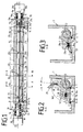
- valve bar 1 is equipped with a rigid profile, which is referred to as valve bar 1.
- the valve bar 1 is provided with two bearing journals 12, 12a, which are received by the bearing housings 11, 11a located in the interior of the recipient 3 or are mounted in these.
- the sealing groove for the sealing ring 6 sealing the lock opening 14 is located in the sealing plate 7. Since the thickness of the valve plate 2 is reduced, the passage width or slot width M is increased.
- valve plate 2 The fastening of the valve plate 2 to the valve bar 1 with the aid of two spring bars 5, 5a represents a joint that is joint-free and therefore friction-free, movable in two axes, and which prevents the relative movements of the valve plate 2 / valve bar 1 that occur when the valve is actuated Generate joint friction and thus wear particles.
- the spring bars 5, 5a are arranged on the valve plate 2 and the valve beam 1 in such a way that they with the help special clamping pieces 4, 4a, 4b, ... or 24, 24a, ..., which are fastened with screws 28 to the valve beam 1 or to the valve plate 2, are pressed into corresponding V-shaped grooves 16, 17.
- These V-grooves 16, 17 and 22, 23 are designed so that, when the spring bars 5, 5a are not tensioned, the valve plate 2 assumes a defined, non-parallel position (angle ⁇ ) with respect to the valve bar 1, so that the valve plate sealing surface D on both during the closing process O-ring 6 on the outside and on the inside of the O-ring at the same time.
- the non-parallel position mentioned results from the uneven depth (dimension X) of the grooves 22, 23 (see FIG. 4) to the plane P.
- the sealing plate 2 continues to move in a straight line, regardless of the fastening locations of the spring bars 5, 5a on the valve beam 1, which rotate about the bearing axis D, until the pressing process has ended (FIG. 3).
- the torque required for valve actuation is introduced symmetrically via both ends of the valve bar 1 by means of two pneumatic rotary drives 10, 10a.
- the elongated shafts 18, 18a of these rotary drives protrude through the pressure stages 9, 9a into the recipient 3.
- the sealing elements 19, 19a, ... of the pressure stages 9, 9a thus seal on the drive shafts 18, 18a, which are not subject to any bending stress. This means that the sealing effect cannot be impaired by transverse displacement of the shaft axes.
- the shaft ends of the drive units are designed as forks 20, 20a, which slide during assembly of the rotary drives 10, 10a over the transverse springs 8, 8a fixedly mounted in the bearing journals (hollow journals) 12, 12a of the valve beam 1. Since the transverse springs 8, 8a are perpendicular to the sealing surface D (not - as drawn for a better understanding - parallel to this), there is no edge pressure on the mating surfaces of the cross spring drive shaft forks 20, 20a during the deflection of the valve beam 1 and therefore also no additional stress the drive shafts 18, 18a.
- valve bearing housing and the compression housing are designed separately, the pressure stage and drive unit can be easily replaced in the event of maintenance or repairs be, while the actual heavy valve unit can remain completely assembled in the recipient 3.
Landscapes
- Engineering & Computer Science (AREA)
- General Engineering & Computer Science (AREA)
- Mechanical Engineering (AREA)
- Physical Vapour Deposition (AREA)
- Lift Valve (AREA)
Applications Claiming Priority (2)
| Application Number | Priority Date | Filing Date | Title |
|---|---|---|---|
| DE4203473 | 1992-02-07 | ||
| DE4203473A DE4203473A1 (de) | 1992-02-07 | 1992-02-07 | Drehschleuse zum ein- und/oder ausbringen eines substrats aus der einen in eine benachbarte behandlungskammer |
Publications (3)
| Publication Number | Publication Date |
|---|---|
| EP0554522A2 true EP0554522A2 (fr) | 1993-08-11 |
| EP0554522A3 EP0554522A3 (en) | 1993-10-27 |
| EP0554522B1 EP0554522B1 (fr) | 1995-01-04 |
Family
ID=6451125
Family Applications (1)
| Application Number | Title | Priority Date | Filing Date |
|---|---|---|---|
| EP92119075A Expired - Lifetime EP0554522B1 (fr) | 1992-02-07 | 1992-11-06 | Excluseur rotatif pour le transport d'un substrat d'une enceinte de traitement à une enceinte de traitement voisine |
Country Status (4)
| Country | Link |
|---|---|
| US (1) | US5205532A (fr) |
| EP (1) | EP0554522B1 (fr) |
| JP (1) | JPH05271933A (fr) |
| DE (2) | DE4203473A1 (fr) |
Cited By (4)
| Publication number | Priority date | Publication date | Assignee | Title |
|---|---|---|---|---|
| EP1806525A3 (fr) * | 2006-01-06 | 2010-12-15 | Applied Materials, Inc. | Porte courbée de vanne à fente avec des raccords flexibles |
| EP2315236A1 (fr) | 2009-10-22 | 2011-04-27 | VAT Holding AG | Soupape de transfert à clapets |
| EP2355132A1 (fr) | 2010-02-04 | 2011-08-10 | VAT Holding AG | Soupape de transfert à clapets dotée de barres de fermeture de soupape pivotantes |
| DE102024129341A1 (de) | 2024-10-10 | 2026-04-16 | Singulus Technologies Aktiengesellschaft | Schleusenventil |
Families Citing this family (16)
| Publication number | Priority date | Publication date | Assignee | Title |
|---|---|---|---|---|
| US5379984A (en) * | 1994-01-11 | 1995-01-10 | Intevac, Inc. | Gate valve for vacuum processing system |
| DE19500964A1 (de) | 1995-01-14 | 1996-07-18 | Leybold Ag | Vorrichtung zum Beschichten |
| US6050446A (en) * | 1997-07-11 | 2000-04-18 | Applied Materials, Inc. | Pivoting lid assembly for a chamber |
| US6202669B1 (en) * | 1998-12-29 | 2001-03-20 | Honeywell International Inc. | Self-aligning valve |
| US6427969B1 (en) * | 2001-04-27 | 2002-08-06 | Helix Technology Inc. | Adjustable gate valve assembly for vacuum chamber |
| DE10247002B3 (de) * | 2002-10-09 | 2004-02-26 | Applied Films Gmbh & Co. Kg | Durchlauf-Beschichtungsanlage |
| KR100512740B1 (ko) * | 2003-06-19 | 2005-09-07 | 삼성전자주식회사 | 반응장치 |
| DE10341244A1 (de) * | 2003-09-03 | 2005-05-12 | Creavac Creative Vakuumbeschic | Einrichtung zur Vakuumbeschichtung wenigstens einer Aufzeichnungsschicht auf mindestens ein optisches Aufzeichnungsmedium |
| DE102004027752A1 (de) * | 2004-06-08 | 2006-01-05 | Leybold Optics Gmbh | Schleusenvorrichtung |
| US7357371B2 (en) * | 2006-04-03 | 2008-04-15 | Daniel Industries, Inc. | Isolation valve seal |
| DE102007013637B4 (de) * | 2007-03-19 | 2018-12-20 | Ewald Dörken Ag | Verfahren zum Beschichten von metallischen Werkstücken |
| WO2012037984A1 (fr) * | 2010-09-24 | 2012-03-29 | Applied Materials, Inc. | Dispositif de séparation des gaz et son procédé de fonctionnement |
| US8459022B2 (en) * | 2011-02-17 | 2013-06-11 | Honeywell International Inc. | Wastegate plug |
| US9376930B2 (en) * | 2013-10-30 | 2016-06-28 | Hyundai Motor Company | Waste gate valve |
| WO2020197589A1 (fr) * | 2018-11-08 | 2020-10-01 | S.P.M. Flow Control, Inc. | Soupape à clapet antiretour dotée d'un élément d'étanchéité de siège de soupape |
| US11982359B2 (en) * | 2019-07-31 | 2024-05-14 | Applied Materials, Inc. | Isolation valve |
Family Cites Families (11)
| Publication number | Priority date | Publication date | Assignee | Title |
|---|---|---|---|---|
| FR390165A (fr) * | 1908-05-12 | 1908-09-28 | Lucien Millet | Robinet de vapeur |
| US1656185A (en) * | 1924-12-20 | 1928-01-17 | Karl A Enz | Valve |
| US2247773A (en) * | 1939-02-15 | 1941-07-01 | Stephen M Dunn | Valve |
| US2522732A (en) * | 1946-02-06 | 1950-09-19 | Sprague Meter Company | Gas pressure regulator valve |
| US2767738A (en) * | 1950-12-27 | 1956-10-23 | Blaw Knox Co | Valve assembly for metallurgical furnaces or the like |
| US2939616A (en) * | 1958-01-21 | 1960-06-07 | Farrel Birmingham Co Inc | Door structure for rubber mixers and the like |
| US3727880A (en) * | 1970-12-22 | 1973-04-17 | Stock Equipment Co | Valve |
| US3972504A (en) * | 1974-12-02 | 1976-08-03 | Ametek, Inc. | Main steam isolation check valve |
| GB1570066A (en) * | 1976-12-16 | 1980-06-25 | Dobson C | Fluid tight locks |
| JP2714833B2 (ja) * | 1988-12-18 | 1998-02-16 | 日本真空技術株式会社 | 仕込・取出室 |
| EP0389820B1 (fr) * | 1989-03-30 | 1993-06-16 | Leybold Aktiengesellschaft | Dispositif pour faire entrer ou sortir par une écluse une pièce dans une chambre à vide |
-
1992
- 1992-02-07 DE DE4203473A patent/DE4203473A1/de not_active Withdrawn
- 1992-06-02 US US07/892,288 patent/US5205532A/en not_active Expired - Fee Related
- 1992-11-06 DE DE59201151T patent/DE59201151D1/de not_active Expired - Fee Related
- 1992-11-06 EP EP92119075A patent/EP0554522B1/fr not_active Expired - Lifetime
-
1993
- 1993-02-04 JP JP5017344A patent/JPH05271933A/ja active Pending
Cited By (8)
| Publication number | Priority date | Publication date | Assignee | Title |
|---|---|---|---|---|
| EP1806525A3 (fr) * | 2006-01-06 | 2010-12-15 | Applied Materials, Inc. | Porte courbée de vanne à fente avec des raccords flexibles |
| EP2315236A1 (fr) | 2009-10-22 | 2011-04-27 | VAT Holding AG | Soupape de transfert à clapets |
| US8870158B2 (en) | 2009-10-22 | 2014-10-28 | Vat Holding Ag | Flap transfer valve with pivoting bearing |
| US8870157B2 (en) | 2009-10-22 | 2014-10-28 | Vat Holding Ag | Flap transfer valve with valve cover |
| EP2355132A1 (fr) | 2010-02-04 | 2011-08-10 | VAT Holding AG | Soupape de transfert à clapets dotée de barres de fermeture de soupape pivotantes |
| US8622368B2 (en) | 2010-02-04 | 2014-01-07 | Vat Holding Ag | Flap transfer valve with pivotable valve closure beam |
| DE102024129341A1 (de) | 2024-10-10 | 2026-04-16 | Singulus Technologies Aktiengesellschaft | Schleusenventil |
| WO2026077820A1 (fr) | 2024-10-10 | 2026-04-16 | Singulus Technologies Ag | Valve de blocage |
Also Published As
| Publication number | Publication date |
|---|---|
| EP0554522A3 (en) | 1993-10-27 |
| US5205532A (en) | 1993-04-27 |
| DE59201151D1 (de) | 1995-02-16 |
| DE4203473A1 (de) | 1993-08-12 |
| JPH05271933A (ja) | 1993-10-19 |
| EP0554522B1 (fr) | 1995-01-04 |
Similar Documents
| Publication | Publication Date | Title |
|---|---|---|
| EP0554522B1 (fr) | Excluseur rotatif pour le transport d'un substrat d'une enceinte de traitement à une enceinte de traitement voisine | |
| EP2215387B1 (fr) | Soupape de dépression | |
| WO2010065976A1 (fr) | Suspension d'une lame de soupape à une tige de soupape | |
| DE4435538C2 (de) | Verfahren zur Herstellung eines Flachsiebes | |
| EP0279177A1 (fr) | Vanne à volume de fuite | |
| EP2315236A1 (fr) | Soupape de transfert à clapets | |
| DE10352143B4 (de) | Längserstreckte Vakuumanlage zur ein- oder beidseitigen Beschichtung flacher Substrate | |
| DE4109467A1 (de) | Dokumentenvernichter | |
| DE2739828C2 (de) | Einrichtung zur Analyse von Proben | |
| DE202004005216U1 (de) | Umsetzbares Wartungsventil | |
| EP1753990B1 (fr) | Dispositif de blocage | |
| DE102008010956A1 (de) | Gliederschürze | |
| EP0394855A1 (fr) | Dispositif de déviation et/ou de division d'un courant de gaz | |
| EP3707450B1 (fr) | Robinet-vanne | |
| DE3050419C2 (de) | Vakuumkammer f}r einen Teilchenbeschleuniger | |
| DE2810660C3 (de) | Dichtungseinrichtung an der Einlaß- oder Auslaßöffnung eines Unter- oder Überdruckbehälters o.dgl. | |
| DE3720001A1 (de) | Vakuumventil | |
| DE19954644C2 (de) | Plattenventil für Vakuumanlagen | |
| DE2925394C2 (de) | Industrieofen | |
| EP0305549B1 (fr) | Chambre de decalaminage de feuillards avec des poudres abrasives | |
| CH700247B1 (de) | Vakuumventil mit Dichtungsträgereinsatz. | |
| EP0481234B1 (fr) | Vanne d'arrêt pour fermer une conduite | |
| WO1989005206A1 (fr) | Installation de soudage par bombardement electronique de pieces a usiner | |
| EP2033788A2 (fr) | Chambre d'encrage | |
| EP0258475A1 (fr) | Vanne à tiroir pour vide |
Legal Events
| Date | Code | Title | Description |
|---|---|---|---|
| PUAI | Public reference made under article 153(3) epc to a published international application that has entered the european phase |
Free format text: ORIGINAL CODE: 0009012 |
|
| AK | Designated contracting states |
Kind code of ref document: A2 Designated state(s): BE CH DE LI |
|
| PUAL | Search report despatched |
Free format text: ORIGINAL CODE: 0009013 |
|
| AK | Designated contracting states |
Kind code of ref document: A3 Designated state(s): BE CH DE LI |
|
| 17P | Request for examination filed |
Effective date: 19931110 |
|
| 17Q | First examination report despatched |
Effective date: 19940324 |
|
| GRAA | (expected) grant |
Free format text: ORIGINAL CODE: 0009210 |
|
| AK | Designated contracting states |
Kind code of ref document: B1 Designated state(s): BE CH DE LI |
|
| REF | Corresponds to: |
Ref document number: 59201151 Country of ref document: DE Date of ref document: 19950216 |
|
| PLBE | No opposition filed within time limit |
Free format text: ORIGINAL CODE: 0009261 |
|
| STAA | Information on the status of an ep patent application or granted ep patent |
Free format text: STATUS: NO OPPOSITION FILED WITHIN TIME LIMIT |
|
| 26N | No opposition filed | ||
| PGFP | Annual fee paid to national office [announced via postgrant information from national office to epo] |
Ref country code: CH Payment date: 20001016 Year of fee payment: 9 |
|
| PGFP | Annual fee paid to national office [announced via postgrant information from national office to epo] |
Ref country code: DE Payment date: 20001020 Year of fee payment: 9 |
|
| PGFP | Annual fee paid to national office [announced via postgrant information from national office to epo] |
Ref country code: BE Payment date: 20001107 Year of fee payment: 9 |
|
| PG25 | Lapsed in a contracting state [announced via postgrant information from national office to epo] |
Ref country code: LI Free format text: LAPSE BECAUSE OF NON-PAYMENT OF DUE FEES Effective date: 20011130 Ref country code: CH Free format text: LAPSE BECAUSE OF NON-PAYMENT OF DUE FEES Effective date: 20011130 Ref country code: BE Free format text: LAPSE BECAUSE OF NON-PAYMENT OF DUE FEES Effective date: 20011130 |
|
| BERE | Be: lapsed |
Owner name: BALZERS UND LEYBOLD DEUTSCHLAND HOLDING A.G. Effective date: 20011130 |
|
| PG25 | Lapsed in a contracting state [announced via postgrant information from national office to epo] |
Ref country code: DE Free format text: LAPSE BECAUSE OF NON-PAYMENT OF DUE FEES Effective date: 20020702 |
|
| REG | Reference to a national code |
Ref country code: CH Ref legal event code: PL |