EP0554525B1 - Méthode pour l'exploitation transparante d'un dispositif de transmission - Google Patents
Méthode pour l'exploitation transparante d'un dispositif de transmission Download PDFInfo
- Publication number
- EP0554525B1 EP0554525B1 EP92119113A EP92119113A EP0554525B1 EP 0554525 B1 EP0554525 B1 EP 0554525B1 EP 92119113 A EP92119113 A EP 92119113A EP 92119113 A EP92119113 A EP 92119113A EP 0554525 B1 EP0554525 B1 EP 0554525B1
- Authority
- EP
- European Patent Office
- Prior art keywords
- station
- command
- req
- block
- highest
- Prior art date
- Legal status (The legal status is an assumption and is not a legal conclusion. Google has not performed a legal analysis and makes no representation as to the accuracy of the status listed.)
- Expired - Lifetime
Links
- 230000005540 biological transmission Effects 0.000 title claims abstract description 184
- 238000000034 method Methods 0.000 title claims abstract description 107
- 230000001960 triggered effect Effects 0.000 claims abstract description 62
- 230000000977 initiatory effect Effects 0.000 claims description 4
- 238000004519 manufacturing process Methods 0.000 claims description 3
- 230000002950 deficient Effects 0.000 claims 4
- 230000006870 function Effects 0.000 description 295
- 230000004044 response Effects 0.000 description 74
- 238000012790 confirmation Methods 0.000 description 61
- 238000010586 diagram Methods 0.000 description 18
- 241001136792 Alle Species 0.000 description 3
- 230000005856 abnormality Effects 0.000 description 1
- 238000001514 detection method Methods 0.000 description 1
- 238000005516 engineering process Methods 0.000 description 1
- 239000003999 initiator Substances 0.000 description 1
- 230000008520 organization Effects 0.000 description 1
- 238000011084 recovery Methods 0.000 description 1
Images





Classifications
-
- H—ELECTRICITY
- H04—ELECTRIC COMMUNICATION TECHNIQUE
- H04L—TRANSMISSION OF DIGITAL INFORMATION, e.g. TELEGRAPHIC COMMUNICATION
- H04L1/00—Arrangements for detecting or preventing errors in the information received
- H04L1/0078—Avoidance of errors by organising the transmitted data in a format specifically designed to deal with errors, e.g. location
- H04L1/0083—Formatting with frames or packets; Protocol or part of protocol for error control
-
- H—ELECTRICITY
- H04—ELECTRIC COMMUNICATION TECHNIQUE
- H04L—TRANSMISSION OF DIGITAL INFORMATION, e.g. TELEGRAPHIC COMMUNICATION
- H04L12/00—Data switching networks
- H04L12/28—Data switching networks characterised by path configuration, e.g. LAN [Local Area Networks] or WAN [Wide Area Networks]
- H04L12/40—Bus networks
- H04L12/407—Bus networks with decentralised control
- H04L12/413—Bus networks with decentralised control with random access, e.g. carrier-sense multiple-access with collision detection [CSMA-CD]
-
- H—ELECTRICITY
- H04—ELECTRIC COMMUNICATION TECHNIQUE
- H04L—TRANSMISSION OF DIGITAL INFORMATION, e.g. TELEGRAPHIC COMMUNICATION
- H04L1/00—Arrangements for detecting or preventing errors in the information received
- H04L1/004—Arrangements for detecting or preventing errors in the information received by using forward error control
- H04L1/0041—Arrangements at the transmitter end
- H04L1/0042—Encoding specially adapted to other signal generation operation, e.g. in order to reduce transmit distortions, jitter, or to improve signal shape
-
- H—ELECTRICITY
- H04—ELECTRIC COMMUNICATION TECHNIQUE
- H04L—TRANSMISSION OF DIGITAL INFORMATION, e.g. TELEGRAPHIC COMMUNICATION
- H04L1/00—Arrangements for detecting or preventing errors in the information received
- H04L1/004—Arrangements for detecting or preventing errors in the information received by using forward error control
- H04L1/0072—Error control for data other than payload data, e.g. control data
Definitions
- the invention relates to a method for clear operation of a transmission device according to the preamble of claim 1.
- the transmission device is used to transmit a large quantity of information and is preferably a public telephone device or a credit telephone device.
- the transmission network is then a switchable network, namely the public telephone network.
- the invention is based on the object of realizing a particularly simple and clear method and a method of the type mentioned at the outset which corresponds to the latest and most modern requirements of transmission technology.
- a simplified transmission device shown symbolically in FIG. 1 consists of a plurality of subscriber stations, each having a computer arrangement and functioning as transmitting / receiving stations, via a transmission network 1 are connected to each other and are only called abbreviations below.
- the transmission network 1 preferably contains a plurality of switches and / or dialers for establishing a physical transmission connection between two of the stations.
- the stations TS1 to TS4 are e.g. B. all identical.
- Each station TS1 to TS4 contains a computer arrangement 7, a modem (modulator-demodulator) 8 and a transceiver 9, which are connected in cascade in the order specified.
- the connection 10 of the transceiver 9 of the station TS1 is thus connected via the transmission network 1 to the connection 10 of the transceiver 9 of the station TS2.
- the information is transmitted between the two stations TS 1 and TS2 in half-duplex or duplex mode at a transmission speed of 300 or 1200 baud / second.
- the levels AP, TR, DK and PH of each station are arranged in cascade in the order specified, that is to say in the order of their ranking, with a connection 11 of the cascade arrangement AP; TR; DK; PH is the connection of the computer arrangement 7 which is connected in the station concerned to a connection 12 of the modem 8 for the purpose of forming the cascade circuit 7; 8; 9.
- the levels PH of the two stations TS1 and TS2 are connected to one another via the transmission medium PH MED .
- Each active element of a level only works together with active elements of one or two levels immediately adjacent in the hierarchy and in the cascade arrangement AP; TR; DK; PH.
- the active elements of the same level communicate with each other only via the level that is directly subordinate to the relevant level in the hierarchy and in the cascade arrangement AP; TR; DK; PH.
- service call commands and service display messages are triggered, which are referred to briefly below as commands (“request”) or as displays (“indication”).
- commands requests
- displays indication
- the direction of signal flow of the commands runs from a higher level to a lower level, while the direction of signal flow of the displays in each case runs from a lower level to a higher level.
- a signal flow SR TS1 or SR TS2 of the commands triggered in the station TS1 or TS2 has a direction, in the order given, from the level AP via the level TR and the level DK to level PH.
- the displays triggered by these commands in the station TS2 or TS1 then each have a signal flow SI TS2 or SI TS1 there.
- the signal flow SI TS2 or SI TS1 has a direction in the station TS2 or TS1, in the order given, from the PH level via the DK level and the TR level to the AP level.
- a command is translated into an access to a primitive, the designation of which ends with an abbreviation REQ ("request"), while an advertisement is translated into an access to another primitive, the designation of each with an abbreviation IND ("indication ”) ends.
- a first station which triggers an information transmission is referred to as the primary station and a second station which is then connected to the primary station for transmission purposes is referred to as the secondary station.
- the primary station has an identifier INI ("Initiator Identifier") and the selected secondary station has one Address ADR.
- the identifier INI and the address ADR are e.g. B. Telephone numbers.
- the primary and the secondary station are both transmitting and receiving stations.
- station TS1 is the primary station and station TS2 is the secondary station.
- the direction of transmission from the primary station TS1 to the secondary station TS2 is referred to as the transmission direction and that from the secondary station TS2 to the primary station TS1 as the feedback direction.
- the highest level AP serves as an interface between the information transmission and the application using the transmitted information.
- the users of the transmission device and / or the applications in which the transmission device is used only have access to the highest level AP by entering the commands and information to be transmitted there and / or evaluating the transmitted information collected there.
- the AP level of each station is capable of handling more extensive information in one operation than the TR level of the same station can process in one operation. Your task is, among other things, to prepare the information to be transmitted ("information") and / or files ("files”) in a clear manner. Access to the content of the information is always immediate, while access to the file content generally requires the operating system (“operating system”) to be called beforehand.
- the AP level of the relevant station causes the information or data to be transmitted to be transferred File contents are divided into shorter information or file blocks which are to be transmitted one after the other and are therefore processed one after the other in the TR level of the station in question.
- the information or file blocks received in another station are then put together again in the order in which they appear there to form the relevant information or file contents.
- the information and file blocks are called data blocks in the following and have a block length, the value of which is denoted by L TS .
- the blocks each have a header, which consists of two letters, as a special identification feature.
- Each data block consists of the header, which is followed by data values or by a file content. At least the last block of the information or file contents to be transmitted is marked with a special identifier, e.g. B. provided a head part DL or FL. For this purpose, a distinction is made as to whether the data block in question is a last or a last block of the information or file contents to be transmitted. If the data block contains data values, then its header is preferably DB ("data block”) for a non-last block and DL ("last data block”) for a last block. If, on the other hand, the data block contains a file content, then its header is preferably FB ("file block”) for a non-last block and FL (“last file block”) for a last block.
- Fig. 3 is shown schematically how the information to be transmitted INFO or file contents COFI in z. B.
- five equal-sized data blocks BL2 to BL6 can be subdivided, each of which is preceded by a header DB or FB for the last data blocks BL2 to BL5 or a header DL or FL in the last data block BL6.
- Each command block consists of a header GF or FH, which is followed by a file name, the header GF ("Get File”) for a file call command and the header FH (“File Header ”) belongs to a file command.
- Each control block consists of the header, that of nothing (in the case of FA, FE and DC), of the identifier INI of the primary station TS1 and of a value L TS1 of a block length in the order given (in the case of CO) or of one L TS value followed a block length (in the case of CC).
- the file names each consist of one or more block letters, the number of which depends on the operating system.
- the identifier INI consists e.g. B. from 1 to 20 ASCII characters.
- the choice of the value L TS of the block length to be used in an upcoming transmission session is selected subject of a negotiation between the two affected stations TS1 and TS2. For this purpose, at the beginning, before the transmission of the information INFO or file contents COFI and preferably on the occasion of the establishment of the transmission connection, respectively a maximum value L TS1 of the block length desired by the primary station TS1 is transmitted from the primary station TS1 to the selected secondary station TS2.
- the maximum value L TS1 of the block length received in the connected secondary station TS2 and desired by the primary station TS1 is compared in the secondary station TS2 with a maximum value L TS2 of the block length desired by the latter.
- the secondary station TS2 selects the lowest value L TS of the two desired values L TS1 and L TS2 as that value of the block length which is subsequently to be used in the transmission session, and then shares this selected value, preferably by means of a control block CC L TS the block length of the primary station TS1 with.
- the two subscriber stations TS1 and TS2 then use the selected value L TS for the block length of the blocks to be generated by their level AP, which is then in each case equal to or less than L TS1 .
- the command APDA-REQ in the AP level of the primary station TS1 causes the information to be transmitted INFO to be subdivided into a block 1 and a block 2, which are processed further by the TR level of the primary station TS1 in the order specified and are received in the order Secondary station TS2 on its AP level triggers a display APDA-IND as soon as the last block 2 of the information INFO identified by a header DL has been received. Of the The information content of the APDA-IND display is then available to the user of the TS2 secondary station.
- the command APSENFI-REQ in the level AP of the primary station TS1 causes a file to be transmitted to be divided into a name block of the file having a header FH, a block 1 and a block 2, which are separated from the level TR of the primary station TS1 in the specified sequence are processed further and their reception in the secondary station TS2 in the AP level triggers an APSENFI-IND display as soon as the last block 2 of the file identified by a header FL has been received, with simultaneous return to the primary station TS1 of a control Blocks FA to confirm that the file has been received correctly.
- the information contained in the APSENFI-IND display is then available to the user of the TS2 secondary station.
- the command APGETFI-REQ in the AP level of the primary station TS1 causes a name block having a header GF of a called-up file to be transmitted and that the Receiving the file name in the secondary station TS2 on the AP level triggers an APGETFI-IND display and an APSENFI-REQ command.
- the latter causes in the AP level of the secondary station TS2 that the file in question is subdivided into a name block of the file having a header FH, a block 1 and a block 2, which are further processed by the TR level of the secondary station TS2 in the order specified and their reception in the primary station TS1 in the AP level triggers an APSENFI-IND display as soon as the last block 2 of the file identified by a header FL has been received, with simultaneous return to the secondary station TS2 of a control block FA for the confirmation of an error-free one Received the file.
- the levels AP of the primary station TS1 and the secondary station TS2 e.g. B. transfer the following blocks in the specified order:
- the command APSENFI-REQ in the AP level of the primary station TS1 causes a file to be transmitted to be divided into a name block of the file having a header FH, an information block 1 and a block 2 which are generated by the TR level of the primary station TS1 are processed further in the specified order and their reception in the secondary station TS2 in their AP level, since it is faulty, triggers an indication APAB-IND as soon as the error has been discovered, ie for example as soon as the last block 2 identified by a header FL File has been received, while sending back to the primary station TS1 a control block FE to confirm an incorrect receipt of the file.
- the receipt of the control block FE in the primary station TS1 in turn triggers a display APAB-IND there in the level AP.
- the information content of one display APAB-IND is now available to the users of the stations TS1 and TS2.
- the command APGETFI-REQ in the AP level of the primary station TS1 causes a name block of a called file having a header GF to be processed further.
- the receipt of the file name in the secondary station TS2 triggers an APGETFI-IND display and an APSENFI-REQ command in its AP level.
- the latter causes in the AP level of the secondary station TS2 that the file in question is divided into a name block of the file having a header FH, a block 1 and a block 2 by the TR level of the secondary station TS2 in the order specified to be processed further.
- an APAB-IND display is triggered in the AP level of the secondary station TS2, the information content of which is now available to the user of the secondary station TS2.
- the level TR initiates a point-to-point information transmission which is independent of the type of transport network used. It ensures that the blocks are in the correct condition and in the correct order are further processed and deals with all recovery problems which are associated with missing or out-of-order blocks.
- the transmission speed in the level TR of the primary station TS1 is determined so that it matches the information reception capability of the selected secondary station TS2.
- the level TR of a station allows the full use of the services which are provided by the level DK of the station in question and allows in a clear manner to process block lengths in one operation which are much larger than those which are provided by the level DK of the concerned station can be processed in one operation.
- Each block contains at least one data packet. If the level TR of a station processes a block length in one operation, the value L TS is greater than the one that can be processed in one operation by the level DK of the same station, ie the block with its identifier or header DB / DL or FB / FL longer than a maximum permitted length of a data packet, then the level TR causes the block to be transmitted, together with its identifier or header DB / DL or FB / FL, to be divided into shorter data packets which are within of a transmission time assigned to the block in question are to be transmitted one after the other and are therefore processed one after the other in the level DK of the relevant station.
- the data packets received in another station are then combined again in the order in which they appear there to form the relevant block.
- each block its data packets are numbered consecutively in their chronological order and the data packets are provided with the packet number thus obtained.
- the packet number is incremented by one each time a packet is transmitted and is not reset to zero at the start of a new block.
- Each data packet consists of a header, which is followed in the order given by the packet number and the packet content. At least the last data packet within each block is marked with a special identifier, e.g. B. provided a head part L.
- the non-last data packets of each block then preferably have a header D ("normal packet"), while the last data packet of each block has a header L ("last packet").
- the packet number and the identifier L or header D / L are each transmitted together with the relevant data packet.
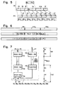
- FIG. 4 schematically shows how a data block BL2 provided with a header DB or FB in z.
- B five equal-sized packets PA1 to PA5 are subdivided, each of which is preceded by a header D in the last packets PA1 to PA4 and a header L in the last packet PA5 in order to form the data packets D1, D2, D3, D4 and L5.
- the command and control blocks are so short that they only consist of a single data packet.
- control packets each of which has a header C, A or E as a special identification feature.
- the control package consists of the header, which is followed by nothing or a control message consisting of block letters.
- the sending station expects a response from the receiving station with regard to the quality of the block received.
- the receiving station also checks the parcel number of the parcels transmitted. If the block consists of several packets and its transmission was error-free, the receiving station in question sends a control packet A back to the transmitting station in response. If the block consists of only a single packet, the confirmation of receipt of the latter is regarded as a confirmation of receipt for the entire block and a separate additional confirmation of receipt of the block by means of the control packet A is no longer required, so that the latter does not must be transferred. If there is an abnormality in the information transmission, such as B. in the presence of a packet number error, there is an appropriate notification of the sending station on the part of the receiving station and the exchange of information between the two stations is interrupted.
- the command TRDA-REQ in the level TR of the primary station TS1 causes the data block to be transmitted to be subdivided into a data packet D0, a data packet D1 and a data packet L2 by the level DK of the primary station TS1 are processed further in the specified order and their reception in the secondary station TS2 in the TR level triggers a display TRDA-IND as soon as the last data packet L2 identified by a header L of the block has been received, while simultaneously returning a control to the primary station TS1 Package A to confirm that the data block has been received correctly.
- the information content of the TRDA-IND display is in turn forwarded to the AP level of the secondary station TS2.
- the command TRDA-REQ in the TR level of the primary station TS1 causes the data block to be transmitted, since it is very short, to be treated as the only data packet L0, which is then further processed by the DK level of the primary station TS1 and is received in the secondary station TS2 in its TR level triggers a display TRDA-IND as soon as the only and last data packet L0 identified by a header L of the data block has been received.
- the information content of the TRDA-IND display is in turn forwarded to the AP level of the secondary station TS2. Since the data block consists of only a single data packet L0, no control packet A is sent back to the primary station TS1.
- the command TRDA-REQ in the TR level of the primary station TS1 causes the data block to be transmitted to be subdivided into a data packet D0, a data packet D1 and a data packet L2 by the level DK of the primary station TS1 processed in the order given.
- the reception of the control packet E in the primary station TS1 triggers there also a TRAB-IND display in the TR level.
- the information content of each TRAB-IND display is in turn forwarded to the AP level of its respective station TS1 or TS2.
- the command TRDA-REQ in the level TR of the primary station TS1 causes the data block to be transmitted to be subdivided into a data packet D0, a data packet D1 and a data packet L2 by the level DK of the primary station TS1 processed in the order given. Since the waiting time in the TR level of the primary station TS1 has expired before the transmission of the block has been confirmed by a control packet A, a TRAB-IND display is triggered in the TR level of the primary station TS1, the information content of which is sent to the AP level of the primary station TS1 is forwarded.
- the level DK regulates the exchange of information between two stations connected by means of the physical medium PH MED and provides an information transmission connection which is relatively independent of the type of the level PH.
- Each level DK causes the generation of preferably ISO-standardized HDLC sequence structures ("High level data link control frame structures").
- ABM procedure Asynchronous Balanced Mode Procedure
- the so-called ABM procedure is preferably used in the method according to the invention, which allows an asynchronous information exchange between two equivalent stations.
- Each The station can send commands at any time and initiate the sending of responses without first waiting for permission from the other station.
- the DK level of each sending station causes all packets to be transmitted, i.e. H. all data packets to be transmitted and all control packets to be transmitted, including, if available, their packet number and their identifier D or L, are encoded in accordance with the HDLC standard in order to form coded information frames.
- the DK level of each transmitting station causes the generation of coded command control frames SABM and DISC and the DK level of each receiving station the generation of coded response control frames RR, RNR, FRMR and UA. All control frames to be transferred, i. H. all command-control frames to be transmitted and all response-control frames to be transmitted are preferably coded in accordance with the HDLC standard.
- the packets to be transmitted together with, if available, their package number and their identifier, as well as the command control frames SABM and DISC to be transmitted, are provided with an error-detecting code in order to generate them in the level DK of a subscriber station TS1 or TS2 working as a transmitting station one coded frame each. After receiving the latter in a subscriber station TS2 or TS1 operating as a receiving station, the received coded frame is decoded there in the level DK and checked for existing errors with the aid of the error-detecting code. In the DK level of the receiving station TS2 resp. TS1 then triggers a DKDA-IND display.
- the package PA is z. B. a data packet and then has a header D or L.
- the packet PA together with its header is converted into a standardized information frame consisting of several fields, which according to the HDLC standard starts in the order specified Sync field ("Start Flag ") 13, an address field 14, a control field 15, an information field 16, a frame control field FCS (" Frame Checking Sequence ”) and a final synchronization field (“ Stop Flag ”) 17 All fields, except the information field 16 and the frame control field FCS, each consist of one byte.
- the start and stop synchronization fields 13 and 17 are preferably identical according to the HDLC standard and each equal to a byte 01111110.
- the information field 16 contains the packet PA to be transmitted together with its header and consists, for. B. from an integer number of bytes. In Fig. 5, it was assumed to consist of 2 bytes.
- the associated values of an HDLC packet counter are contained in the control field 15 of the relevant information frame, namely that value of the HDLC packet counter of the last information packet sent as the value N (S) in bits 2 to 4 and that value of the HDLC -Packet counter of the last received information packet as value N (R) in bits 6 to 8, with bit 4 or bit 8 corresponding to the MSB within N (S) or N (R).
- Bit 1 of the control field 15 of each information frame has a logic value "0" and is in each case the first transmitted bit of the relevant control field 15.
- the control frames are either so-called S-control frames ("Supervisory Control Frames”), which are provided with a running count, or so-called U-control frames ("Unnumbered Control Frames”), which have no running count.
- the S control frame is always a response control frame RR or RNR, while the U control frame is either a command control frame SABM or DISC or a response control frame UA or FRMR . All S and U control frames, with the exception of the FRMR response control frame, have no information field 16.
- the information content contained and to be transmitted is in control field 15 of the S or U control control concerned. Frame included.
- the first two bits of the control field 15 of the S-control frame are each equal to 10 and those of the U-control frame are each equal to 11.
- Bit 3 and bit 4 of the control field 15 of the S-control frame are contained the functional content of the latter, while bits 6 to 8 contain the value of the serial number N (R) of the next expected information frame.
- Bit 3 and bit 4 as well as bit 6 to bit 8 of the control field 15 of the U-control frame contain the functional content of the latter and the relevant control field 15 has no serial number.
- the response control frames FRMR have an information field 16, the first eight bits of which contain the content of the control field 15 of the associated transmitted information frame which is recognized as being seriously faulty.
- the ninth bit has a logic value "0".
- Bits 10 to 12 contain a value N (S) of the serial number of the information frame sent and bits 14 to 16 contain a value N (R) of the serial number of the received information frame.
- Bit 13 has a logic value "0" if the transmitted information identified as faulty was a command, and a logic value "1" if this information was an answer.
- the type of error detected can be specified in further bits 17 to 20 of the information field 16.
- Bit 5 of the control field 15 of the command control frames SABM and DISC and the information frames transmitted in the transmission direction is referred to as the P bit ("Poll Command Bit”).
- Bit 5 of the control field 15 of the response control frames RR, RNR, FRMR and UA and of the information frames transmitted in the feedback direction is referred to as an F bit ("Response Final Bit”).
- the response control frame is either a special information frame I R , in the control field 15 of which the F bit has a logic value "1", or one of the response control frames RR, RNR, FRMR or UA.
- the response control frame RR serves to confirm that a received transmitted frame is free of errors and is a sign that the receiving station in question is ready to receive a new frame again.
- the response control frame RNR (Receive Not Ready), on the other hand, serves to confirm that the receiving station in question is not yet ready to receive a new information frame.
- the response control frame FRMR (Frame Response Mode Reject) serves to confirm a lack of understanding when receiving a transmitted frame and is a sign that a serious error has occurred in the transmission of the last transmitted frame and the transmission connection is usually new must be initiated.
- the receipt of a response control frame FRMR in the DK level triggers a display DKAB-IND.
- the control field 15 of the command control frame SABM (“Set Asynchronous Balanced Mode") is preferably 1111P100 and that of the command control frame DISC ("Diconnect”) is preferably 1100P010. Both command control frames thus have a P bit as the fifth bit.
- the command control frame DISC is used to resolve the existing transmission connection, the secondary station TS2 always having to answer receipt of the command control frame DISC with a response control frame UA.
- the frame control field FCS of the frame is used for error detection and consists of two bytes, the bit values of which are derived from the values of the remaining bits of the frame in question in a manner described in the ISO standard 3309 ("International Standard Organization" standard) will.
- the receiving station simply ignores the reception of any information frame or command control frame received with an error.
- the level PH permits the establishment of a physical transmission connection, e.g. B. a telephone connection between two stations, maintaining this transmission connection, a resolution of this transmission connection, a display of unforeseen connection interruptions and the creation of a completely clear information transmission.
- the level PH of the transmitting station causes each coded frame to be transmitted to be divided into bit groups, to which a subsequent stop bit and no control bits are added, the bit groups then together with their stop bit within one of the coded ones Transmission time assigned to the frame can be transmitted successively from the transmitting station via the transmission network 1 to a receiving station.
- the stop bit serves as a synchronization bit.
- the bit groups BY0, ..., BY7 received in the receiving station are combined there in the order in which they were received to form a coded receive frame.
- 5 shows how an encoded information frame 13; 14; 15; 16; FCS; 17 is divided into eight bit groups BY0 to BY7, to each of which a stop bit ST is added at the end.
- a byte is preferably selected as the bit group BY0 to BY7, which is then followed by the stop bit ST during the transmission.
- the transmission network 1 is a switchable network
- the method according to the invention preferably contains a first method stage VS1, in which, prior to the transmission of the information INFO (see FIG 6) or the file contents COFI (see FIG. 11), first of all the transmission connection between the primary station TS1 and the secondary station TS2 is established.
- the information INFO actually to be transmitted is then transmitted from the transmitting station TS1 to the receiving station TS2 in at least one further method stage VS2 of the method according to the invention.
- a last method stage VS3 of the method according to the invention the existing transmission connection between the two stations TS1 and TS2 is finally released.
- the process stages VS1, VS2 and VS3 are run through in time by a process program in the order specified.
- the blocks and packets sent by the station TS2 are shown hatched in FIG. 6 and FIG. 11.
- the second, third, fifth, seventh and eighth package thus have a header L as the last package of their respective block and are therefore labeled L0 (from TS1), L0 (from TS2), L2, L3 or L4.
- the fourth packet is not the last packet of its block BL2 and therefore has a header D. It is therefore designated D1.
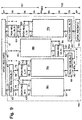
- the functional arrangement 18 has an input 19, a first one Output 20 and a second output 21 and consists of two function blocks 22 and 23 of the PH level of the primary station TS1, of two function blocks 24 and 25 of the PH level of the secondary station TS2 and of a function block 26 of the DK level of the secondary station TS2.
- the latter has a first output 27 and a second output 28.
- a command 29 of the DK level of the primary station TS1 reaches an input of the function block 22 via the input 19, in which it triggers a command PHDA-REQ.
- the latter causes a frame coded in accordance with the HDLC standard to be transmitted in bit groups BY0 to BY7 via the transmission medium PH MED to the secondary station TS2, where its reception in function block 24 of the PH level triggers a display PHDA-IND.
- the latter in turn triggers a DKDA-IND display in the function block 26 of the DK level of the secondary station TS2, the information content of which, interpreted in accordance with HDLC, is sent to the secondary station TS2 via the first output 27 of the function block 26 and the first output 20 of the functional arrangement 18 of the TR level .
- the display DKDA-IND also triggers a confirmation of receipt by triggering a command PHDA-REQ via the second output 28 of the function block 26 in the function block 25 of the PH level of the secondary station TS2, which causes a response control frame RR , RNR or FRMR in bit groups BY0 to BY7 is transmitted via the transmission medium PH MED to the primary station TS1, where its reception in the function block 23 of the PH level triggers a display PHDA-IND, the information content of which is sent via the second output 21 of the function arrangement 18 the DK level of the primary station TS1 is forwarded, where it is interpreted according to HDLC.
- Each coded frame 13; 14; 15; 16; FCS; 17 is transmitted in bit groups BY0 to BY7 by triggering the PHDA-REQ command in function block 22 of the PH level of the transmitting station TS1 or TS2 for the purpose of subdivision of the coded frame 13; 14; 15; 16; FCS; 17 in the bit groups BY0 to BY7.
- the bit groups BY0 to BY7 received in the receiving station TS2 or TS1 are combined there in the order in which they were received to form a coded receiving frame and are then solved in Function block 24 of the PH level of the receiving station TS2 or TS1 displays a display PHDA-IND.
- a command PHDA-REQ is triggered in function block 25 of the PH level of the receiving station TS2 or TS1 for the purpose of transmission via the transmission network 1 of a response control frame RR, RNR or FRMR serving as a confirmation of receipt , the reception of which then triggers a display PHDA-IND in function block 23 of level PH, whereupon the information content of the packet last transmitted from the transmitting station TS1 or TS2 to the receiving station TS2 or TS1 is deemed to have been correctly received if the response control frame is on Response control frame RR is deemed to have been received incorrectly if the response control frame is a response control frame RNR, and is to be received seriously incorrectly if the control response frame is a control response frame FRMR.
- a first output 46 of the function block 30 leads to a first input 47 of the function block 31 and a second output 48 to the input of the function block 32.
- a first one Output 49 of the function block 31 is connected in the order given via the function blocks 34 and 37 to the physical medium PH MED .
- the latter is connected to a first input 50 of the function block 38, the output of which is led via the physical medium PH MED to the input of the function block 40, the output of which is connected to the level DK of the secondary station TS2.
- the latter level DK is connected to the input of the function block 41, the output of which is led to the input of the function block 39 via the physical medium PH MED .
- the output of the latter is connected to the level DK of the primary station TS1.
- This level DK leads to a second input 51 of the function block 31.
- a second output 53 of the function block 31 is guided by means of a first input 54 of the function block 35 via the latter to the input 19 of the function arrangement 18a, the first output 20 of which is at the level TR of the secondary station TS2 and the second output 21 is at the level DK of the primary station TS1 is connected.
- the latter level DK is in turn connected to a second input 55 of the function block 35 and an input 56 of the function block 30.
- the output of the function block 32 is led by means of a first input 57 of the function block 36 via the latter to the input 19 of the function arrangement 18b, the first output 20 of which is connected to the input of the function block 43 and the second output 21 of which is via the DK level of the primary station TS1 a second input 58 of the function block 36 is connected.
- the output of the function block 43 is routed to the input of the function block 45 and the output of the latter to the input of the function block 44.
- the output of the latter is connected to a first input 59 of the function block 42, the output of which is led to the input 19 of the function arrangement 18c.
- the first output 20 of the latter is connected via function block 33 to the level AP of the primary station TS1 and the second output 21 to the level DK of the secondary station TS2. This level DK is in turn connected to a second input 60 of the function block 42.
- the first process stage VS1 contains the following process steps:
- the user of the primary station TS1 selects an address ADR of a secondary station TS2 to be selected and thereby triggers a first command APCO-REQ in the function block 30 of the AP level of the primary station TS1 to establish a transmission connection (e.g. a telephone connection) between the two stations TS1 and TS2.
- a transmission connection e.g. a telephone connection
- the fourth command DKCO-REQ (see function block 34) in turn triggers in function block 37 of the PH level of the primary station TS1 a command PHCO-REQ from each to establish a physical connection through the levels PH of the two stations TS1 and TS2 and through the transmission medium PH MED in order to implement the required physical connections to the secondary station TS2 having the address ADR.
- a command PHDA-REQ is triggered in function block 38 of the PH of the primary station TS1 for transmission in bit groups BY0 to BY7 of a command control frame SABM from the primary station TS1 via the transmission medium PH MED to the secondary station TS2, where its reception in function block 40 triggers a display PHDA-IND.
- the information content of the display PHDA-IND is forwarded to the level DK of the secondary station TS2 on the one hand for the realization of the required logic connections there and on the other hand for the triggering of a receipt confirmation there. Since the received command control frame SABM contains transmitted data, which may have been corrupted during the transmission, the correct or incorrect reception of the command control frame SABM of the primary station TS1 must be confirmed.
- the level DK of the secondary station TS2 in function block 41 of the level PH of the secondary station TS2 triggers a command PHDA-REQ, which transmits a transmission from the secondary station TS2 via the transmission medium PH MED to the primary station TS1 of a response control frame UA, DM or FRMR initiated.
- Its reception in the primary station TS1 triggers a display PHDA-IND in the function block 39 of the PH level, the information content of which is then forwarded to the level DK of the primary station TS1, where it receives an answer control frame UA via the input 51 of the Function block 31 causes the TR level to trigger the fifth command DKDA-REQ in the level DK of the primary station TS1, since the correct reception of the command frame SABM is interpreted as the correct execution of the fourth command DKCO-REQ (see function block 34). The correct execution of the latter is thus communicated indirectly to the primary station TS1 by means of the transmission of the response control frame UA.
- the fifth command DKDA-REQ (see function block 35) then in turn initiates the transmission of a control packet C by triggering a command PHDA-REQ in the function block 22 in its function block 22 for transmission in bit groups BY0 to BY7 of the control package C.
- the information content of a display DKDA-IND (see function block 26) appears at the first output 20 of the function arrangement 18a and is used to initiate the secondary station TS2 Level TR forwarded.
- a confirmation of receipt of the control packet G in the form of a response-control frame, response-control frame RR, RNR or FRMR appears at the second output 21 of the functional arrangement 18a.
- the third command TRDA-REQ in turn causes the transmission of a control block CO ("Connect") consisting of a single data packet PA0, which contains at least the identifier INI of the primary station TS1, but preferably also the maximum value desired by the latter L TS1 of the block length contains.
- the third command TRDA-REQ triggers a sixth command DKDA-REQ in the function block 36 of the DK level of the primary station TS1 for the purpose of starting the transmission from the primary station TS1 to the secondary station TS2 of the only data packet PA0 of the control block CO, by operating within the Function arrangement 18b (see FIG. 7) in whose function block 22 triggers a command PHDA-REQ for transmission in bit groups BY0 to BY7 of the data packet PA0.
- Display DKDA-IND in function block 26 (see FIG. 7) and this triggers a display TRDA-IND via the first output 20 of function arrangement 18b in function block 43, which in turn triggers an indication APCO-IND in function block 45.
- the reception in the secondary station TS2 of the control block CO thus triggers both a display TRDA-IND in the TR level and an display APCO-IND in the AP level.
- the information content INI and L TS1 of the control block CO is thus available to the secondary station TS2.
- a receipt confirmation in the form of a response control frame RR, RNR or FRMR appears at the second output 21 of the functional arrangement 18b.
- the secondary station TS2 compares the received value L TS1 with the desired value L TS2 of the block length and selects the smaller of the two values L TS1 or L TS2 as the definitive value L TS of the block length to be used for the transmission during the current transmission session .
- This selected smaller value L TS of the block length is then preferably communicated to the primary station TS1 in the following way:
- the reception of the maximum value L TS1 of the block length desired by the primary station TS1 triggers the display APCO-IND (see function block 45) in the level AP of the secondary station TS2, which in turn triggers a command TRDA-REQ in function block 44 of the level TR of the secondary station TS2 triggers, which causes a control block CC ("Connect Confirm"), which has the selected smaller value L TS of the block length as information content, to be transmitted.
- the control block CC consists of a single data packet, which is labeled L0.
- the command TRDA-REQ triggers a command DKDA-REQ in the function block 42 of the level DK of the secondary station TS2, which causes the only data packet contained in the control block CC from the secondary station TS2 via the transmission network 1 to the primary station TS1 is transmitted.
- the command DKDA-REQ within the functional arrangement 18c triggers a command PHDA-REQ in its functional block 22 for transmission in bit groups BY0 to BY7 of the relevant data packet.
- a display DKDAIND thereby appears in the function block 26 (see FIG. 7).
- the receipt of the control block CC in the primary station TS1 or the display DKDA-IND triggers a display TRDA-IND via the first output 20 of the function arrangement 18c in the function block 33 of the level TR of the primary station TS1 as a sign that the first process stage VS1 is finished.
- the information content of the TRDA-IND display is therefore forwarded to the AP level of the primary station TS1 as a confirmation of receipt in order to trigger the next command in the AP level, which, as already mentioned, is the first command of the VS2 process level (see FIG. 9). .
- the selected and transmitted value L TS of the block length is now also available to the primary station TS1, so that it knows which value of the block length it has to use in the current transmission session.
- a confirmation of receipt of the control block CC in the form of a response control frame RR, RNR or FRMR appears at the second output 21 of the functional arrangement 18c.
- the input of function block 42 of level DK of secondary station TS2 for. B. initiates a retransmission of the data packet of the control block CC.
- the level DK of the secondary station TS2 is given a confirmation of correct receipt of the last sent command DKDA-REQ (see function block 42).
- a first output 71 of the function block 61 is led to a first input 72 of the function block 62 and a second output 73 to the input of the function block 63.
- a first output 74 of the function block 62 is connected to a first input 75 of the function block 64, the output of which is led to the input 19 of the function arrangement 18d, the first output 20 of which in turn is connected to the level TR of the secondary station TS2.
- the second output 21 of the function arrangement 18d is led via the level DK of the primary station TS1 to a second input 76 of the function block 62 on the one hand and to a second input 77 of the function block 64 on the other hand.
- a second output 78 of the function block 62 is connected to a first input 79 of the function block 65, the output of which is led to the input 19 of the function arrangement 18e, the first output 20 of which in turn is connected to a first input of the function block 68.
- a first output 80 of the latter leads to the level AP of the secondary station TS2, while a second output 81 of the function block 68 is connected to a first input 82 of the function block 67.
- the second output 21 of the function arrangement 18e is routed on the one hand via the DK and the TR level of the primary station TS1 to a first input 83 of the function block 61 and on the other hand in the DK level of the primary station TS1 to a second input 84 of the function block 65.
- a first output of the function block 67 is connected to the input 19 of the function arrangement 18f connected, the first output 20 of which is led via the level TR of the primary station TS1 to a second input 85 of the function block 61, while the second output 21 of the function arrangement 18f is connected in the level DK of the secondary station TS2 to a second input 86 of the function block 67.
- a second output 82a of the function block 67 is connected to a second input of the function block 68 via the levels TR and AP of the secondary station TS2.
- the output of the function block 63 is routed to a first input 87 of the function block 66, the output of which is connected to the input 19 of the function arrangement 18g, the first output 20 of which in turn is routed via the function block 69 to the input of the function block 70.
- the second output 21 of the function arrangement 18g is connected on the one hand via the levels DK and TR to a third input 88 of the function block 61 and on the other hand in the level DK to a second input 89 of the function block 66.
- Process stage VS2 contains the following process steps:
- a first piece of information to be transmitted in function block 61 of the AP level of the primary station TS1 triggers a first command APDA-REQ for the sequential transmission of all information to be transferred INFO.
- the first command APDA-REQ of the AP level firstly causes the information INFO which is too extensive to be divided into two shorter information blocks BL2 and BL3, which are then transmitted one after the other in the order given.
- the first third command DKDA-REQ (see function block 64) initiates the transmission of the information packet D1 from the primary station TS1 via the transmission network 1 to the secondary station TS2 by operating within the function arrangement 18d (see FIG. 7) in its function block 22 triggers a command PHDA-REQ for transmission in bit groups BY0 to BY7 of the information packet D1.
- the information content of a display DKDA-IND (see function block 26) appears at the first output 20 of the function arrangement 18d, which in turn is forwarded to the level TR of the secondary station TS2.
- a appears at the second output 21 of the functional arrangement 18d Acknowledgment of receipt in the form of a response control frame RR, RNR or FRMR.
- a response control frame RNR is in the level DK of the primary station TS1 via the input 77 of the function block 64 z.
- B. triggered a retransmission of the information packet D1.
- the level TR of the primary station TS1 is given a confirmation of the correct receipt of the first third command DKDA-REQ via the input 76 of the function block 62, so that the level TR in the function block 65 of the level DK is the second third command DKDA-REQ can trigger.
- the second third command DKDA-REQ (see function block 65) then in turn causes the transmission of the information packet L2 from the primary station TS1 via the transmission network 1 to the secondary station TS2 by operating within the function arrangement 18e (see FIG. 7)
- Function block 22 triggers a command PHDA-REQ for transmission in bit groups BY0 to BY7 of the information packet L2.
- the information content of a display DKDA-IND appears at the first output 20 of the function arrangement 18e, which in turn triggers a display TRDA-IND in function block 68.
- a receipt confirmation in the form of a response control frame RR, RNR or FRMR appears at the second output 21 of the functional arrangement 18e.
- the primary station TS1 is connected via the input 84 of the function block 65 z. B. triggered a retransmission of the information packet L2.
- confirmation of correct receipt of the second third command DKDA-REQ is given via level TR and input 83 of function block 61 of level AP of primary station TS1.
- the display TRDA-IND triggers a command DKDA-REQ after the receipt of all information packets D1 and L2 of the information block BL2 via the second output 81 of the function block 68 in the function block 67 of the DK level of the secondary station TS2 in order to start the transmission of a first one Control packet A if the reception of the relevant information block BL2 was error-free, or a second control packet E if the reception of the relevant information block BL2 was faulty.
- This command DKDA-REQ then triggers the transmission of the control packet A or E by triggering a command PHDA-REQ in the function block 18f (see FIG.
- the function block 61 in the primary station TS1 triggers the second second command TRDA-REQ via its second output 73 (see function block 63).
- a display TRAB-IND is triggered in the level TR of the primary station TS1, which is not shown in FIG. 9 for reasons of clarity in the drawing.
- This second second command TRDA-REQ triggers as many commands DKDA-REQ in the specified order in the order DK of the primary station TS1 in time as there are information packets in the information block BL3, i. H. 6, a single command DKDA-REQ.
- This command DKDA-REQ causes in function block 66 that the transmission of information packet L3 is triggered, which has a header L as the only and last packet of its information block BL3.
- the level DK of the primary station TS1 waits and waits for confirmation of correct receipt of this command on the part of the secondary station TS2. Only after receipt of this confirmation does the level TR of the primary station TS1 trigger the start of the next method level VS3 via its level AP.
- the command DKDA-REQ in the function block 66 causes the transmission of the information packet L3 of the information block BL3 from the primary station TS1 via the transmission network 1 to the secondary station TS2 by operating within the function arrangement 18g (see FIG. 7) in its function block 22 triggers a command PHDA-REQ for transmission in bit groups BY0 to BY7 of the information packet L3.
- a display DKDA-IND appears in the function block 26 (see FIG. 7) and this triggers a display TRDA-IND via the first output 20 of the function arrangement 18g in the function block 69, which in turn triggers an APDA-IND display in function block 70.
- a receipt confirmation in the form of a response control frame appears at the second output 21 of the functional arrangement 18g RR, RNR or FRMR.
- the primary station TS1 is in the level DK via the input 89 of the function block 66 z. B. triggered a retransmission of the information packet L3.
- confirmation of correct receipt of the last information packet L3 of the last information block BL3 is given via the DK and the level TR and the input 88 of the function block 61 of the level AP of the primary station TS1 , so that the level AP of the primary station TS1 can trigger the next process stage VS3.
- An additional confirmation of correct receipt of the entire information block BL3 by means of a control packet A is not necessary here, since the information block BL3 consists of only a single information packet L3.
- the appearance in the secondary station TS2 of the last received information packet L2 or L3 of each information block BL2 or BL3 has triggered a display TRDA-IND in the function block 68 or 69 in the level TR of the secondary station TS2.
- the appearance in the secondary station TS2 of the received last information packet L3 of the last information block BL3 of the information INFO has also triggered a display APDA-IND in the function block 70 in the level AP of the secondary station TS2 in order to indicate the end of the transmission of all information to be transmitted INFO.
- a first output 102 of the function block 90 is led to the input of the function block 91 and a second output 103 to the input of the function block 92.
- the output 104 of the function block 91 is connected to a first input 105 of the function block 93, the output of which is led to the input 19 of the function arrangement 18h, the first output 20 of which in turn is connected to the input of the function block 101 via the function block 100.
- the second output 21 of the function arrangement 18h is routed on the one hand via the DK and the TR level of the primary station TS1 to the input 106 of the function block 90 and on the other hand in the level DK of the primary station TS1 to a second input 107 of the function block 93.
- the output of the function block 92 is connected to a first input 108 of the function block 94, the first output 109 of which is connected to the input of the function block 95.
- the output of the latter is connected via the physical medium PH MED to the input of the function block 98, the output of which in turn is connected to the level DK of the secondary station TS2.
- the latter level is also connected to the input of function block 99.
- the output of the latter is routed via the physical medium PH MED to the input of the function block 96, the output of which in turn is connected to a second input 110 of the function block 94.
- a second output 111 of the latter is routed via function block 97 to the physical medium PH MED .
- Process stage VS3 contains the following process steps:
- the second command TRDA-REQ (see function block 91) in turn triggers a fourth command DKDA-REQ in function block 93 of level DK of primary station TS1 for the purpose of transmitting the only packet L4 contained in the last block BL4, which contains the control block DC.
- the level DK of the primary station TS1 waits and waits for confirmation of correct receipt of this command on the part of the secondary station TS2. Only after receipt of this confirmation does level TR release level AP of primary station TS1 for the purpose of triggering in function block 92 of the third command TRDC-REQ.
- the fourth command DKDA-REQ causes the transmission of the packet L4 by being within the function arrangement 18h (see FIG. 7) in its function block 22 triggers a command PHDA-REQ for transmission in bit groups BY0 to BY7 of the packet L4.
- a command PHDA-REQ for transmission in bit groups BY0 to BY7 of the packet L4.
- the information content of a display DKDA-IND appears at the first output 20 of the function arrangement 18h.
- This display DKDA-IND or the receipt of the last control block DC in the secondary station TS2 causes the initiation of the latter to be canceled and a display TRDA-IND in the function block 100 or in the level TR and in the level AP of the secondary station TS2 APDC-IND is triggered in function block 101.
- a receipt confirmation in the form of a response control frame RR, RNR or FRMR appears at the second output 21 of the functional arrangement 18h.
- the level TR of the primary station TS1 is given a confirmation of a correct execution of the fourth command DKDA-REQ, so that the level TR of the primary station TS1 in function block 90 can release its level AP for the purpose of triggering the third Command TRDC-REQ (see function block 92) in the TR level of the primary station TS1.
- the third command TRDC-REQ in turn triggers a fifth command DKDC-REQ in the function block 94 of the level DK of the primary station TS1, which in turn causes a command PHDA-REQ in the function block 95 and a command PHDC-REQ to follow one another in chronological order in function block 97, the level PH of the primary station TS1 is triggered.
- the PHDA-REQ command is used to resolve the existing logic connections in the DK level of the secondary station TS2. After this command has been triggered, the level DK of the primary station TS1 waits and waits for confirmation of correct receipt of this command on the part of the secondary station TS2. Only after receipt of this confirmation does the level DK of the primary station TS1 trigger the command PHDC-REQ in the level PH of the primary station TS1.
- the PHDA-REQ command (see function block 95) of the PH level of the primary station TS1 triggers the transmission of a last command control frame DISC, which is in bit groups BY0 to BY7 from the primary station TS1 via the transmission network 1 to the secondary station TS2 is transmitted, where its reception in function block 98 triggers a display PHDA-IND, which in turn causes the logic connections present there to be broken up on the level DK of the secondary station TS2, which the primary station TS1 then uses a last response control Frame UA is communicated, which is transmitted from the secondary station TS2 via the transmission network 1 to the primary station TS1.
- the level DK of the secondary station TS2 triggers a command PHDA-REQ in the function block 99 of the level PH of the secondary station TS2 to start the transmission of the last response control frame UA.
- the latter is transmitted in the feedback direction in bit groups BY0 to BY7 via the transmission medium PH MED to the primary station TS1 and its reception then triggers a display PHDA-IND there in function block 96 of level PH, the information content of which then follows function block 94 of level DK the primary station TS1 is forwarded.
- the fifth command DKDC-REQ then, after receiving the last response control frame UA in the primary station TS1, triggers the PHDC-REQ command in function block 97 of the PH level of the primary station TS1, which in turn causes the between the Both stations TS1 and TS2 existing physical connections are resolved.
- the transmission device thus returns to its original state and is available again for further transmissions.
- the file block BL2 consisting of a single file packet L1
- the file Block BL3 consists of two file packages D2 and L3
- the file block BL4 consists of a single file package L4, which are to be transmitted one after the other in the order specified.
- the file block BL2 contains the name FNA ("File Name") of the file to be transferred and the file blocks BL3 and BL4 the content of this file.
- the file name FNA is assigned a special identifier or header FH, which together with the file name FNA forms the only file package L1 of the file block BL2.
- the last file block BL4 of the file is provided with a special identifier or header part FL, which is different from the relevant special identifier or header part DL of the last block of the information not to be transmitted contained in a file.
- the function block 113 is similar to the function block 61 (see FIG. 9) with the difference that in addition to the three inputs 83, 85 and 88 and the two outputs 71 and 73 there is also a fourth input 121 and a third output 122.
- the inputs 83, 85 and 88 as well as the outputs 71 and 73 are connected to the functional arrangement 112 in exactly the same way as was given on the occasion of the description of the flow chart shown in FIG. 9.
- the third output 122 of the function block 113 leads to the input of the function block 114.
- the output of the latter is connected to a first input 123 of the function block 116, the output of which is led to the input 19 of the function arrangement 18j, the first output 20 of which in turn is connected to the level AP of the secondary station TS2 via the function block 118.
- the second output 21 of the function arrangement 18j is routed on the one hand via the DK and TR levels of the primary station TS1 to the fourth input 121 of the function block 113 and on the other hand in the level DK of the primary station TS1 to a second input 124 of the function block 116. That output of the function arrangement 112 which is connected to the input of the function block 70 in FIG.
- the output of the latter is connected via function block 119 to a first input 125 of function block 117.
- the output of the latter is led to the input 19 of the functional arrangement 18k, the first output 20 of which in turn is connected via the function block 115 to the level AP of the primary station TS1.
- the second output 21 of the functional arrangement 18k is guided in the level DK of the secondary station TS2 to a second input 126 of the functional block 117.
- Process stage VS4 contains the following process steps: After the transmission connection between the two stations TS1 and TS2 has been established in the first process stage VS1, in process stage VS4 a first piece of information to be transmitted in function block 113 of the AP level of the primary station TS1 triggers a first command APSENFI-REQ for the temporally successive transmission first the file name FNA in the file block BL2, then the file content in the file blocks BL3 and BL4.
- the first command APSENFI-REQ triggers a preceding command TRDA-REQ before the second commands TRDA-REQ (see 62 and 63) are triggered in function block 114 of level TR of the primary station TS1.
- the latter causes the transfer of the file block BL2, which has FH as the header and the file name FNA as the content.
- the level TR of the primary station TS1 waits and waits for confirmation from the secondary station TS2 that the command has been carried out correctly. Only after receiving this confirmation does the AP level of the primary station TS1 trigger the next command in the functional arrangement 112.
- the preceding command TRDA-REQ (see function block 114) in turn triggers a first additional command DKDA-REQ in function block 116 of level DK of the primary station TS1 for the purpose of transmitting the name FNA of the file to be transmitted in the single file packet L1 which is in the file Block BL2 is included.
- the level TR of the primary station TS1 waits and waits for a confirmation of correct receipt of this command from the secondary station TS2. Only after receipt of this confirmation does level TR release level AP of primary station TS1 for the purpose of triggering the next command in functional arrangement 112.
- the first additional command DKDA-REQ causes the file packet L1 to subsequently be transmitted as the first file packet of the process stage VS4 from the primary station TS1 to the secondary station TS2 by using it within the functional arrangement 18j (see FIG. 7) in their Function block 22 triggers a command PHDA-REQ for transmission in bit groups BY0 to BY7 of the file packet L1. 7, the information content of a DKDA-IND display (see function block 26) appears at the first output 20 of the function arrangement 18j.
- This display DKDA-IND or the receipt of the file packet PA1 triggers a display TRDA-IND in function block 118 of the TR level of the secondary station TS2 as an indication of the receipt of the transmitted file name.
- the content of the TRDA-IND display is in turn forwarded to the AP level of the secondary station TS2.
- a receipt confirmation in the form of a response control frame RR, RNR or FRMR appears at the second output 21 of the functional arrangement 18j.
- the level TR of the primary station TS1 is given a confirmation of the correct execution of the command DKDA-REQ, so that the level TR of the primary station TS1 in function block 113 can release its level AP for the purpose of triggering the next command in the functional arrangement 112.
- the function arrangement 112 then, as indicated in the description of FIG. 9, causes the blocks BL3 and BL4 and thus the content of the file to be transmitted one after the other.
- the appearance in the secondary station TS2 of the received last file packet L4 of the last file block BL4 (see FIG. 11) of the file to be transmitted in the process stage VS4 triggers an indication APSENFI-IND in the function block 120 of the AP level of the secondary station TS2 for the purpose Display of the end of the transfer of the entire file content.
- the display APSENFI-IND After receiving the last file packet L4 of the last file block BL4 of the file in the secondary station TS2, the display APSENFI-IND prompts confirmation of the receipt of the file for the primary station TS1 by one in the function block 119 of the TR level of the secondary station TS2 first additional command TRDA-REQ is triggered to start the transmission in the feedback direction a first control block FA if the reception of the file was error-free, or a second control block FE if the reception of the file was faulty.
- the first additional command TRDA-REQ in function block 117 of the DK level of the secondary station TS2 triggers a second additional command DKDA-REQ for the purpose of starting the transmission from the secondary station TS2 to the primary station TS1 of a single one in the first or second control block FA or FE contained package L1.
- the second additional command DKDA-REQ initiates the transmission of the control block FA or FE by triggering a command PHDA-REQ in the functional arrangement 18k (see FIG. 7) in its functional block 22 for transmission in the feedback direction in bit groups BY0 to BY7 of the control block FA or FE.
- a command PHDA-REQ in the functional arrangement 18k (see FIG. 7) in its functional block 22 for transmission in the feedback direction in bit groups BY0 to BY7 of the control block FA or FE.
- the information content of a DKDA-IND display appears at the first output 20 of the function arrangement 18k.
- This display DKDA-IND in turn triggers a display TRDA-IND in the function block 115 that the control block FA or FE has been received in the primary station TS1.
- a receipt confirmation in the form of a response control frame RR, RNR or FRMR appears at the second output 21 of the functional arrangement 18k.
- the primary station TS1 can start the process stage VS4 on its own initiative or the file to be transmitted can also be called up by the secondary station TS2 by means of a file call APGETFI-REQ. In the latter case, after the first process stage VS1 there is a process stage VS5 preceding the process stage VS4, in which a block BLx consisting of a single packet Lx in the feedback direction from the Secondary station TS2 is transmitted to the primary station TS1.
- the output of the function block 131 is connected via the function block 130 to a first input 132 of the function block 129, the output of which is led to the input 19 of the function arrangement 18m.
- the first output 20 of the latter is connected via function block 128 to the input of function block 127.
- the second output 21 of the functional arrangement 18m is led in the level DK of the secondary station TS2 to a second input 133 of the functional block 129.
- the user of the secondary station TS2 in function block 131 triggers the APGETFI-REQ command as a file call in function block 131 in a first subsequent process step of process stage VS5.
- the command APGETFI-REQ in turn triggers a command TRDA-REQ in the function block 130 of the level TR of the secondary station TS2, which causes the transmission in the feedback direction of the block BLx.
- a header GF (“Get File") is assigned to the name FNA of the file as a special identifier, which together with the name FNA of the file forms the block BLx, which, like already mentioned, contains a single package Lx.
- the TRDA-REQ command then triggers a DKDA-REQ command in function block 129 of the DK level of the secondary station TS2, which causes the packet Lx to be transmitted from the secondary station (TS2) to the primary station (TS1).
- the level DK of the secondary station TS2 waits and waits for a confirmation of correct receipt of this command from the primary station TS1.
- the command DKDA-REQ causes the transmission of the packet Lx by triggering a command PHDA-REQ in the function block 18m (see FIG. 7) in its function block 22 for transmission in bit groups BY0 to BY7 of the Package Lx.
- a display DKDA-IND appears at the first output 20 of the function arrangement 18m.
- This display DKDA-IND in turn triggers a display TRDA-IND in function block 128 of the TR level of the primary station TS1 as an indication of the receipt of the transmitted file name.
- the display TRDA-IND in turn triggers an display APGETFI-IND in the function block 127 of the AP level of the primary station TS1 to indicate the end of the transmission of the name FNA of the called file.
- the reception of the packet Lx in the primary station TS1 triggers both the display TRDA-IND in the TR level and the display APGETFI-IND in the AP level.
- a receipt confirmation in the form of a response control frame RR, RNR or FRMR appears at the second output 21 of the functional arrangement 18m.
- Upon receipt of a response control frame RNR is in the DK level of the secondary station TS2 via the input 133 of the function block 129 z.
- the content of the display APGETFI-IND then causes the level AP of the primary station TS1 to start the process level VS4 (see FIG. 12) by triggering the command APSENFI-REQ (see 113) of a subsequent level VS4 in the level AP there which causes the file and its name FNA to be transferred from the Primary station TS1 is transmitted to the secondary station TS2.
- the number of retransmissions is counted using a counter, its value with a predetermined maximum value, e.g. B. three, and if this predetermined maximum value is exceeded, any further retransmission is prevented while triggering a message "fatal error" APAB-IND, TRAB-IND, DKAB-IND or PHAB-IND in all affected levels AP, TR, DK or PH.
- a predetermined maximum value e.g. B. three
Landscapes
- Engineering & Computer Science (AREA)
- Computer Networks & Wireless Communication (AREA)
- Signal Processing (AREA)
- Data Exchanges In Wide-Area Networks (AREA)
- Medicines That Contain Protein Lipid Enzymes And Other Medicines (AREA)
- Reverberation, Karaoke And Other Acoustics (AREA)
- Peptides Or Proteins (AREA)
- Medicines Containing Antibodies Or Antigens For Use As Internal Diagnostic Agents (AREA)
- Devices For Conveying Motion By Means Of Endless Flexible Members (AREA)
- Forging (AREA)
- Massaging Devices (AREA)
- Selective Calling Equipment (AREA)
- Electrotherapy Devices (AREA)
- Communication Control (AREA)
- Glass Compositions (AREA)
- Crystals, And After-Treatments Of Crystals (AREA)
- Manufacturing Of Electric Cables (AREA)
Claims (23)
- Procédé d'exploitation transparente d'un dispositif de transmission destiné à transmettre, par un réseau de transmissions (1), des informations (INFO) et/ou des contenus de fichiers de données (COFI), appelés simplement fichiers dans ce qui suit, entre deux stations participantes (TS1, TS2) qui comportent toutes deux un agencement d'ordinateur (7) et interviennent toutes deux comme stations émettrices/réceptrices,
caractériséen ce qu'il existe, dans l'agencement d'ordinateur (7) de chacune des stations participantes (TS1, TS2) un plan du rang le plus élevé, ou de premier rang (AP), un plan de rang inférieur au précédent ou de deuxième rang (TR), un plan de rang inférieur au précédent ou de troisième rang (DK) et un plan de rang inférieur au précédent ou de dernier rang (PH) dans lesquels des ordres et/ou des indications sont déclenchés, la direction de passage des signaux (SRTS1, SRTS2) des ordres va respectivement d'un plan de rang supérieur vers un plan de rang inférieur et la direction de passage des signaux (SITS1, SITS2) des indications va respectivement d'un plan de rang inférieur vers un plan de rang supérieur,en ce que les utilisateurs du dispositif de transmission et/ou les applications dans lesquelles le dispositif de transmission est utilisé n'accèdent qu'au plan de premier rang (AP) des stations participantes (TS1, TS2),en ce que le plan de premier rang (AP) d'une station participante intervenant comme station primaire (TS1) provoque la division des informations (INFO) et/ou des contenus de fichiers (COFI), à transmettre, en blocs de données (BL2, BL3 ou bien BL2, BL3, BL4) qui doivent être transmis chronologiquement l'un après l'autre et qui contiennent chacun au moins un paquet de données,en ce qu'au moins le dernier bloc de données (BL3 ou bien BL4) des informations (INFO) et/ou des contenus de fichiers (COFI) à transmettre est pourvu d'une première étiquette (DL ou bien FL),en ce que le plan de deuxième rang (TR) amène chacun des blocs de données (BL2 ou bien BL3) qui est avec sa première étiquette (DB, DL ou bien FB, FL) plus long qu'une longueur maximale admissible du paquet de données à être divisé avec sa première étiquette (DB, DL ou bien FB, FL) en paquets de données (D1, L2 ou bien D2, L3) qui doivent être transmis chronologiquement l'un après l'autre à l'intérieur d'un temps de transmission associé au bloc de données concerné (BL2 ou bien BL3),en ce qu'au moins le dernier paquet de données (L2, L3 ou bien L1, L3, L4) est pourvu à l'intérieur de chaque bloc de données (BL2, BL3, ou bien BL2, BL3, BL4) d'une deuxième étiquette (L) qui est respectivement transmise simultanément avec le paquet de données concerné (L2, L3, ou bien L1, L3, L4),en ce que les paquets de données reçus sont assemblés, après la transmission des paquets de données (D1, L2, L3 ou bien L1, D2, L3, L4) en blocs de données (BL2, BL3 ou bien BL2, BL3, BL4) selon la succession de leur apparition dans une station participante intervenant comme station secondaire (TS2), eten ce que les blocs de données assemblés (BL2, BL3, ou bien BL2, BL3, BL4) sont assemblés selon la succession de leur apparition dans la station secondaire TS2), pour former les informations transmises (INFO) ou les contenus de fichiers transmis (COFI). - Procédé selon la revendication 1, caractérisé en ce que les paquets de données (D1, L2, L3 ou bien L1, D2, L3, L4) sont pourvus, selon la succession chronologique de leur transmission, d'un numéro de paquet à numérotation en sens croissant (1, 2, 3 ou bien 1, 2, 3, 4) qui est respectivement transmis en même temps que le paquet de données concerné.
- Procédé selon la revendication 1 ou 2, caractériséen ce qu'un premier ordre (APDA-REQ en 61 ou bien APSENFI-REQ en 113) qui provoque la division, en blocs de données (BL2, BL3 ou bien BL2, BL3, BL4), des informations (INFO) ou des contenus des fichiers (COFI) à transmettre est déclenché dans le plan de premier rang (AP) de la station primaire (TS1),en ce que le premier ordre (APDA-REQ ou bien APSENFI-REQ) déclenche dans le plan de deuxième rang (TR) de la station primaire (TS1) au moins autant de deuxièmes ordres (TRDA-REQ en 62 et 63 de 112) qu'il existe de blocs de données (BL2, BL3, ou bien BL3, BL4) dans les informations (INFO) ou les contenus de fichiers (COFI) à transmettre,en ce chaque deuxième ordre (TRDA-REQ) qui appartient à un bloc de données (BL2 ou bien BL3) qui est avec sa première étiquette (DB, DL ou bien FB, FL) plus long que la longueur maximale admissible du paquet de données provoque la division, en paquets de données (D1, L2, ou bien D2, L3), du bloc de données concerné (BL2 ou bien BL3) avec sa première étiquette (DB, DL, ou bien FB, FL), eten ce que chaque deuxième ordre (TRDA-REQ) déclenche dans le plan de troisième rang (DK) de la station primaire (TS1) au moins autant de troisièmes ordres (DKDA-REQ en 64, 65 ou 66 de 112) qu'il existe de paquets de données (D1, L2 ou L3 ou bien D2, L3 ou L4) contenus dans le bloc de données (BL2 ou BL3 ou bien BL3 ou BL4) appartenant au deuxième ordre concerné (TRDA-REQ).
- Procédé selon l'une des revendications 1 à 3, caractériséen ce que l'apparition, dans la station secondaire (TS2), du dernier paquet de données (L2, L3 ou bien L3, L4) d'un bloc de données (BL2, BL3 ou bien BL3, BL4) reçu dans le plan de deuxième rang (TR) de la station secondaire (TS2) déclenche respectivement une indication (TRDA-IND en 68 ou bien 69 de 112) eten ce que l'apparition, dans la station secondaire (TS2), du dernier paquet de données reçu (L3 ou bien L4) du dernier bloc de données (BL3 ou bien BL4) des informations (INFO) ou des contenus de fichiers (COFI) déclenche dans le plan de premier rang (AP) de la station secondaire (TS2) une indication respective (APDA-IND en 70 ou bien APSENFI-IND en 120) destinée à indiquer la fin de la transmission de toutes les informations (INFO) ou bien de tous les contenus de fichiers (COFI) à transmettre.
- Procédé selon l'une des revendications 1 à 4, caractérisé en ce qu'un ordre (DKDA-REQ en 67 de 112) est déclenché dans le plan de troisième rang (DK) de la station secondaire (TS2), après la réception dans la station secondaire de chaque dernier paquet de données (L2 ou bien L3) d'un bloc de données (BL2 ou bien BL3) qui se compose de plusieurs paquets de données (D1, L2 ou bien D2, L3), ordre qui est déclenché en vue de débuter la transmission d'un premier paquet de contrôle (A), si la réception du bloc de données concerné (BL2 ou bien BL3) est exempte de défauts, ou d'un deuxième paquet de contrôle (E) si la réception du bloc de données concerné (BL2 ou bien BL3) est défectueuse.
- Procédé selon l'une des revendications 3 à 5, caractériséen ce que, dans le cas d'un contenu de fichier (COFI) à transmettre, le premier ordre (APENSI-REQ en 113) déclenche, avant le déclenchement des deuxièmes ordres (TRDA-REQ en 62 et 63 dans 112) dans le plan de deuxième rang (TR) de la station primaire (TS1), un deuxième ordre additionnel précédent (TRDA-REQ en 114) qui déclenche dans le plan de troisième rang (DK) de la station primaire (TS1) un troisième ordre additionnel (DKDA-REQ en 116) en vue de transmettre un nom (FNA) du fichier à transmettre, une troisième étiquette (FH) étant associée au nom (FNA), étiquette qui constitue avec le nom (FNA) du fichier un bloc de données (BL2) qui contient un paquet unique de données (Ll) qui est ensuite transmis de la station primaire (TS1) à la station secondaire (TS2) où sa réception déclenche une indication (TRDA-IND en 118) dans le plan de deuxième rang (TR), eten ce que le dernier bloc de données (BL4) du fichier est pourvu d'une première étiquette (FL) qui est différente de la première étiquette (DL) du dernier bloc de données (BL3) d'informations (INFO) à transmettre, non contenues dans un fichier.
- Procédé selon la revendication 6, caractérisé en ce que, après la réception, dans la station secondaire (TS2), du dernier paquet de données (L4) du dernier bloc de données (BL4) du fichier dans le plan de deuxième rang (TR) de la station secondaire (TS2), un premier ordre additionnel (TRDA-REQ en 119) est déclenché en vue de débuter une transmission d'un premier bloc de contrôle (FA) si la réception du fichier est exempte de défauts, ou d'un deuxième bloc de contrôle (FE) si la réception du fichier est défectueuse, le premier ordre additionnel (TRDA-REQ) déclenché dans le plan de deuxième rang (TR) déclenchant dans le plan de troisième rang (DK) de la station secondaire (TS2) un deuxième ordre additionnel (DKDA-REQ en 117) en vue de débuter la transmission à partir de la station secondaire (TS2) vers la station primaire (TS1) d'un paquet unique (L1) contenu dans le premier ou bien le deuxième blocs de données (FA ou FE).
- Procédé selon la revendication 6 ou 7, caractériséen ce que le fichier à transmettre est appelé par la station secondaire (TS2) (voir Fig. 13) tandis qu'un ordre (APGEFTI-REQ en 131) est déclenché dans une étape précédente du procédé (VS5) dans le plan de premier rang (AP) de la station secondaire (TS2), ordre qui déclenche dans le plan de deuxième rang (TR) de la station secondaire (TS2) un ordre (TRDR-REQ en 130) qui déclenche lui-même dans le plan de troisième rang (DK) de la station secondaire (TS2) un ordre (DKDA-REQ en 129) de débuter la transmission du nom (FNA) du fichier à transmettre, une quatrième étiquette (GF) étant associée au nom (FNA) du fichier, étiquette qui constitue avec le nom (FNA) du fichier un bloc de données (BLx), qui contient un paquet unique de données (Lx), qui est ensuite transmis de la station secondaire (TS2) à la station primaire (TS1) où sa réception déclenche tant dans le plan de deuxième rang (TR) que dans le plan de premier rang (AP) une indication respective (TRDA-IND en 128 ou APGEFTI-IND en 127) destinée à indiquer la fin de la transmission du nom (FNA) du fichier appelé, eten ce que le premier ordre (APSENFI-REQ en 113: Fig. 12) d'une étape suivante (VS4) du procédé est ensuite déclenché dans le plan de premier rang (AP) de la station primaire (TS1), ordre qui provoque la transmission du fichier ainsi que de son nom (FNA), à partir de la station primaire (TS1) vers la station secondaire (TS2).
- Procédé selon l'une des revendications 1 à 8, caractérisé en ce que le réseau de transmission (1) est un réseau commutable (par exemple un réseau téléphonique) et en ce qu'une connexion de transmission est établie entre les deux stations participantes (TS1, TS2) dans une première étape (VS1) du procédé, avant la transmission des informations (INFO) et/ou des contenus de fichiers (COFI).
- Procédé selon la revendication 9, caractériséen ce qu'un premier ordre (APCO-REQ en 30) est déclenché respectivement à la première étape (VS1) du procédé (voir Fig. 8) dans le plan de premier rang (AP) de la station primaire (TS1), ordre qui déclenche respectivement dans le plan de deuxième rang (TR) de la station primaire (TS1) un deuxième ordre (TRCO-REQ en 31) et, après son exécution, un troisième ordre (TRDA-REQ en 32),en ce que le deuxième ordre (TRCO-REQ) déclenche respectivement dans le plan de troisième rang (DK) de la station primaire (TS1) un quatrième ordre (DKCO-REQ en 34) et après l'exécution de celui-ci un cinquième ordre (DKDA-REQ en 35),en ce que le quatrième ordre (DKCO-REQ) provoque d'une part la réalisation de liaisons physiques entre la station primaire (TS1) et une deuxième station participante pourvue d'une adresse (ADR) et intervenant comme station secondaire (TS2) et ensuite, d'autre part, la transmission à partir de la station primaire (TS1) vers la station secondaire (TS2) d'un cadre d'ordre (SABM) de contrôle destiné à y établir des liaisons logiques,en ce que l'exécution du quatrième ordre (DKCO-REQ) de la station primaire est communiquée tandis qu'un cadre de réponse (UA, DM ou FRMR) de contrôle est transmis de la station secondaire (TS2) par le réseau de transmission (1) à la station primaire (TS1), cadre qui est un premier cadre de contrôle (UA) de réponse si la réception du cadre de contrôle (SABM) d'ordre a été exempte de défauts, est un deuxième cadre de contrôle (DM) de réponse si la réception du cadre de contrôle (SABM) d'ordre a été défectueuse et est un troisième cadre de contrôle (FRMR) de réponse si la réception du cadre de contrôle (SABM) d'ordre a été sévèrement défectueuse,en ce que, le cinquième ordre (DKDA-REQ en 35) provoque, après la réception du premier cadre de contrôle (UA) de réponse, la transmission d'un paquet de contrôle (C) à partir de la station primaire (TS1) par le réseau de transmission (1) à la station secondaire (TS2) en vue d'un lancement de cette dernière,en ce que le troisième ordre (TRDA-REQ en 32) déclenche dans le plan de troisième rang (DK) de la station primaire (TS1), après l'exécution du cinquième ordre (DKDA-REQ), un sixième ordre (DKDA-REQ en 36) pour débuter la transmission à partir de la station primaire (TS1) vers la station secondaire (TS2) d'un paquet unique de données (L0) d'un troisième bloc de contrôle (CO) qui contient comme contenu d'informations au moins un identifiant (INI) de la station primaire (TS1), eten ce que la réception du troisième bloc de contrôle (CO dans la station secondaire (TS2) y déclenche, ainsi que dans le plan de deuxième rang (TR) et dans le plan de premier rang (AP), une indication respective (TRDA-IND en 43 ou bien APCO-IND en 45).
- Procédé selon la revendication 10, caractérisé en ce que le troisième bloc de contrôle (CO) contient comme contenu d'informations une valeur maximale (LTS1) de la longueur de bloc, souhaitée par la station primaire (TS1).
- Procédé selon l'une des revendications 1 à 10, caractérisé en ce qu'une valeur maximale (RTS1) de la longueur de bloc souhaitée par la station primaire (TS1) est transmise de la station primaire (TS1) à la station secondaire (TS2) dans une première étape (VS1) du procédé, au commencement, avant la transmission des informations (INFO) ou du contenu de fichiers (COFI).
- Procédé selon la revendication 11 ou 12, caractériséen ce que la valeur maximale (LTS1) de la longueur de bloc souhaitée par la station primaire (TS1), reçue dans la station secondaire (TS2), y est comparée à une valeur maximale (LTS2) de la longueur de bloc souhaitée par la station secondaire (TS2),en ce que la station secondaire (TS2) communique ensuite à la station primaire (TS1) la plus basse des deux valeurs souhaitées (LTS1, LTS2) eten ce que les deux stations participantes (TS1, TS2) utilisent comme valeur (LTS) de la longueur de bloc, lors de la transmission ultérieure des informations (INFO) ou des contenus de fichiers (COFI), la valeur la plus basse des deux valeurs souhaitées (LTS1 et LTS2).
- Procédé selon la revendication 13, caractérisé en ce que la station secondaire (TS2) communique à la station primaire (TS1) la plus basse des deux valeurs souhaitées (LTS1, LTS2) de longueur de bloc au moyen d'un bloc de contrôle additionnel (CC).
- Procédé selon la revendication 14, caractérisé en ce que la réception, dans le plan de premier rang (AP) de la station secondaire (TS2), de la valeur maximale (LTS1) de la longueur de bloc souhaitée par la station primaire (TS1) déclenche une indication (APCO-IND en 45) qui déclenche dans le plan de deuxième rang (TR) de la station secondaire (TS2) un ordre (TRDA-REQ en 44) qui provoque la transmission du bloc additionnel de contrôle (CC) tout en déclenchant dans le plan de troisième rang (DK) de la station secondaire (TS2) un ordre (DKDA-REQ en 42) qui provoque la transmission d'un paquet unique de données (L0) contenu dans le bloc additionnel de contrôle (CC), à partir de la station secondaire (TS2) par le réseau de transmission (1) vers la station primaire (TS1) où la réception du bloc additionnel de contrôle (CC) déclenche dans le plan de deuxième rang (TR) une indication (TRDA-IND en 33) qui termine la première étape (VS1) du procédé.
- Procédé selon l'une des revendications 9 à 15, caractériséen ce qu'un premier ordre (APDC-REQ en 90) est déclenché respectivement dans le plan de premier rang (AP) de la station primaire (TS1), dans une dernière étape (VS3) du procédé (voir Fig. 10), après la transmission de toutes les informations (INFO) ou tous les contenus de fichiers (COFI) à transmettre, ordre qui déclenche respectivement dans le plan de deuxième rang (TR) de la station primaire (TS1) un deuxième ordre (TRDA-REQ en 91) en vue d'une transmission d'un dernier bloc de contrôle (DC) et, après l'exécution du deuxième ordre (TRDA-REQ), un troisième ordre (TRDC-REQ en 92),en ce que le deuxième ordre (TRDA-REQ) déclenche dans le plan de troisième rang (DK) de la station primaire (TS1) un quatrième ordre (DKDA-REQ en 93) en vue d'une transmission d'un dernier paquet unique de données (L4) contenu dans le dernier bloc de contrôle (DC), à partir de la station primaire (TS1) vers la station secondaire (TS2), la réception du dernier bloc de commande (DC) dans la station secondaire (TS2) provoquant une annulation du lancement de cette dernière et le déclenchement, dans le plan de deuxième rang (TR) ainsi que dans le plan de premier rang (AP) de la station secondaire (TS2), d'une indication respective (TRDA-IND en 100 ou bien PADC-IND en 101),en ce que le troisième ordre (TRDC-REQ en 92) déclenche dans le plan de troisième ordre (DK) de la station primaire (TS1), après l'exécution du quatrième ordre (DKDA-REQ), un cinquième ordre (DKDC-REQ en 94) en vue de la transmission d'un dernier cadre de commande (DISC) d'ordre à partir de la station primaire (TS1) vers la station secondaire (TS2) par le réseau de transmission (1),en ce que la réception à la station secondaire (TS2) du dernier cadre de contrôle (DISC) d'ordre provoque dans le plan de troisième rang (DK) de la station secondaire (TS2) le déclenchement de connexions logiques qui y sont présentes, ce qui est communiqué à la station primaire (TS1) au moyen d'un dernier cadre de contrôle (UA) de réponse qui est transmis de la station secondaire (TS2) par le réseau de transmission (1) à la station primaire (TS1), eten ce que le cinquième ordre (DKDC-REQ) provoque, après la réception du dernier cadre de contrôle (UA) de réponse à la station primaire, l'interruption des connexions physiques existantes entre les deux stations participantes (TS1, TS2).
- Procédé selon l'une des revendications 2 à 16, caractériséen ce que des paquets à transmettre (L0 à L5, D1, D2, Lx, C, A, E, L0 de CC, L1 de FA, L1 de FE) accompagnés, si ceux-ci existent, de leur numéro de paquets (0 à 5) et de leur deuxième étiquette (D, L) ainsi que des cadres de contrôle (SABM, DISC) d'ordre à transmettre, sont avant leur transmission pourvus, dans le plan de troisième rang (DK) d'une station participante intervenant comme station émettrice (TS1 ou bien TS2), d'un code de détection de défauts en vue de créer dans chacun un cadre codé respectif (13; 14; 15; 16; FCS; 17),en ce que le cadre codé (13; 14; 15; 16; FCS; 17) reçu dans une station participante intervenant comme station réceptrice (TS2 ou bien TS1) y est décodé, après sa réception, dans le plan de troisième rang (DK) et y est de plus contrôlé à l'aide du code de détection de défauts quant à des défauts présents, eten ce qu'une indication est ensuite déclenchée (DKDA-IND en 26 de 18a à 18m) dans le plan de troisième rang (DK) de la station réceptrice (TS2 ou bien TS1).
- Procédé selon la revendication 17, caractérisé en ce que le cadre codé (13; 14; 15; 16; FCS; 17) est codé selon une norme de procédure de commande de liaison de haut niveau, ou norme HDLC .
- Procédé selon la revendication 17 ou 18, caractériséen ce que la transmission de chaque cadre codé (13; 14; 15; 16; FCS; 17) se produit (voir Fig. 7) tandis qu'un ordre (PHDA-REQ en 22 de 18a à 18m) est déclenché dans le plan de dernier rang (PH) de la station émettrice (TS1 ou bien TS2) en vue de diviser le cadre codé (13; 14; 15; 16; FCS; 17) en groupes de bits (BY0 à BY7) qui sont transmis chronologiquement l'un après l'autre, de la station émettrice (TS1 ou bien TS2) à la station réceptrice (TS2 ou bien TS1) par le réseau de transmission (1), à l'intérieur d'un temps de transmission associé au cadre codé (13; 14; 15; 16; FCS; 17) eten ce que les groupes de bits (BY0 à BY7) reçus à la station réceptrice (TS2 ou bien TS1) y sont assemblés, selon la succession de leur réception, en un cadre de réception codé (13; 14; 15; 16; FCS; 17) et déclenchent ensuite dans le plan de dernier rang (PH) de la station réceptrice (TS2 ou bien TS1) une indication (PHDA-IND en 24 de 18a à 18m).
- Procédé selon la revendication 19, caractérisé en ce que c'est un octet, qui est suivi par un bit d'arrêt (ST), qui est choisi comme groupe de bits (BY0 à BY7).
- Procédé selon l'une des revendications 17 à 20, caractérisé en ce qu'un ordre (PHDA-REQ en 25 de 18a et 18m) est déclenché, après le contrôle quant à la présence de défauts respectivement effectué dans le plan de dernier rang (PF) de la station réceptrice (TS2 ou bien TS1), en vue de la transmission par le réseau de transmission (1) d'un cadre de contrôle (RR, RNR ou FRMR) de réponse qui sert d'accusé de réception, dont la réception déclenche ensuite dans le plan de dernier rang (PH) une indication (PHDA-IND en 23 de 18a à 18m) à la suite de quoi le contenu d'information du paquet transmis en dernier lieu de la station émettrice (TS1 ou bien TS2) à la station réceptrice (TS2 ou bien TS1) est considéré comme correctement reçu si le cadre de contrôle (RR, RNR, FRMR) de réponse est un quatrième cadre de contrôle (RR, RNR, FRMR) de réponse, est évalué comme reçu de façon défectueuse si le cadre de contrôle (RR, RNR, FRMR) de réponse est un cinquième cadre de contrôle (RNR) de réponse, et est évalué comme reçu de façon sévèrement défectueuse si le cadre de contrôle (RR, RNR, FRMR) de réponse est un sixième cadre de contrôle (FRMR) de réponse.
- Procédé selon la revendication 10 ou 21, caractérisé en ce qu'une réception, dans une station participante (TS1 ou bien TS2), du cinquième cadre de contrôle (RNR) de réponse, après l'expédition d'un paquet par cette même station participante (TS1 ou bien TS2), provoque la répétition de l'envoi du paquet concerné.
- Procédé selon l'une des revendications 1 à 22, caractérisé en ce que, lorsque des répétitions d'envoi sont effectuées, leur nombre est compté et est comparé à une valeur maximale prédéterminée, (par exemple trois) et en ce qu'un dépassement de cette valeur maximale prédéterminée empêche toute répétition additionnelle de l'envoi et déclenche simultanément un message "défaut sévère" (APAB-IND, TERAB-IND, DKAB-IND ou PHAB-IND) dans tous les plans concernés (AP, DK, TR ou PH).
Applications Claiming Priority (2)
| Application Number | Priority Date | Filing Date | Title |
|---|---|---|---|
| CH37492 | 1992-02-07 | ||
| CH374/92 | 1992-02-07 |
Publications (2)
| Publication Number | Publication Date |
|---|---|
| EP0554525A1 EP0554525A1 (fr) | 1993-08-11 |
| EP0554525B1 true EP0554525B1 (fr) | 1997-07-30 |
Family
ID=4185568
Family Applications (1)
| Application Number | Title | Priority Date | Filing Date |
|---|---|---|---|
| EP92119113A Expired - Lifetime EP0554525B1 (fr) | 1992-02-07 | 1992-11-07 | Méthode pour l'exploitation transparante d'un dispositif de transmission |
Country Status (7)
| Country | Link |
|---|---|
| EP (1) | EP0554525B1 (fr) |
| KR (1) | KR930018899A (fr) |
| AT (1) | ATE156319T1 (fr) |
| DE (1) | DE59208752D1 (fr) |
| DK (1) | DK0554525T3 (fr) |
| FI (1) | FI930508A7 (fr) |
| NO (1) | NO930393L (fr) |
Families Citing this family (1)
| Publication number | Priority date | Publication date | Assignee | Title |
|---|---|---|---|---|
| JP4033619B2 (ja) * | 2000-05-26 | 2008-01-16 | シャープ株式会社 | サーバ装置 |
Family Cites Families (2)
| Publication number | Priority date | Publication date | Assignee | Title |
|---|---|---|---|---|
| US4680773A (en) * | 1985-10-30 | 1987-07-14 | Microcom, Inc. | Data telecommunications system and method utilizing a multi-mode modem |
| CA1309519C (fr) * | 1987-03-17 | 1992-10-27 | Antonio Cantoni | Transfert de messages dans un systeme a multiplexage |
-
1992
- 1992-11-07 EP EP92119113A patent/EP0554525B1/fr not_active Expired - Lifetime
- 1992-11-07 DK DK92119113.6T patent/DK0554525T3/da not_active Application Discontinuation
- 1992-11-07 AT AT92119113T patent/ATE156319T1/de not_active IP Right Cessation
- 1992-11-07 DE DE59208752T patent/DE59208752D1/de not_active Expired - Fee Related
-
1993
- 1993-02-04 NO NO93930393A patent/NO930393L/no unknown
- 1993-02-05 KR KR1019930001572A patent/KR930018899A/ko not_active Ceased
- 1993-02-05 FI FI930508A patent/FI930508A7/fi unknown
Also Published As
| Publication number | Publication date |
|---|---|
| DK0554525T3 (da) | 1998-02-23 |
| NO930393L (no) | 1993-08-09 |
| KR930018899A (ko) | 1993-09-22 |
| FI930508A0 (fi) | 1993-02-05 |
| DE59208752D1 (de) | 1997-09-04 |
| ATE156319T1 (de) | 1997-08-15 |
| NO930393D0 (no) | 1993-02-04 |
| EP0554525A1 (fr) | 1993-08-11 |
| FI930508A7 (fi) | 1993-08-08 |
Similar Documents
| Publication | Publication Date | Title |
|---|---|---|
| DE69329059T2 (de) | Verfahren und Gerät für sequentielle Rückordnung | |
| DE1512071A1 (de) | Zeitmultiplex-Vermittlungsanlage | |
| EP0794680A2 (fr) | Procédé d'exploitation d'une liaison large bande entre un terminal radio mobile et un dispositif réseau radio mobile, ainsi que terminal, dispositif réseau et système radio | |
| DE10027456A1 (de) | Vorrichtung und Verfahren zum Verbessern der Leistung in Master- und Slave-Kommunikationssystemen | |
| EP0998078A1 (fr) | Méthode pour la configuration d'une liaison de communication pour transmission de données | |
| DE69507724T2 (de) | Methode und verfahren für datenpakete-empfang in einem einwegübertragungsvorrichtung | |
| EP0554525B1 (fr) | Méthode pour l'exploitation transparante d'un dispositif de transmission | |
| EP0105212B1 (fr) | Montage de circuit pour la transmission de signaux entre une ligne d'abonné et au moins une ligne de transmission d'un centre de télécommunications à services integrés | |
| DE68918970T2 (de) | Verfahren zur Feststellung der Gruppennummer für eine Netztrecke. | |
| WO1998019472A2 (fr) | Procede et dispositif pour mettre en relation des abonnes d'un reseau de telecommunications dans un central telephonique | |
| DE2826323B1 (de) | Schaltungsanordnung zum UEbertragen von Signalen zwischen einer Datenuebertragungseinheit und einem Datenendgeraet | |
| EP0475180A1 (fr) | Procédé de transmission de paquets de communication entre des lignes de raccordement existantes dans un commutateur | |
| EP0631455A1 (fr) | Méthode pour la conservation des connections virtuelles après au moins une disparition partielle de branches de connection | |
| DE19731261C2 (de) | Verfahren und Protokoll zur gesicherten Übertragung von Datenpaketen über eine fehlerbehaftete Übertragungsstrecke mit Reihenfolgesteuerung | |
| EP0060921A1 (fr) | Circuit pour la connection d'abonnés de télex raccordés à un central de commutation de données avec des abonnés de télétex raccordés également à ce central de commutation de données | |
| DE3112549C2 (de) | Verfahren zum Austausch von Signalisierinformationen zwischen einer Fernmelde-, insbesondere Fernsprechnebenstellenanlage und dem öffentlichen Fernsprechnetz | |
| DE2452699C3 (de) | Verfahren zur Bestätigung der richtigen Verbindung zwischen zwei Datenendstellen | |
| EP2278758B1 (fr) | Réseau de communication basé sur la priorité et procédé de communication | |
| DE102006018483B4 (de) | Verfahren zur Übertragung von Daten über die DECT-Luftschnittstelle | |
| DE69514077T2 (de) | Schalten eines Endgeräts, wie Faksimilegerät, auf einen von zwei Kanälen | |
| DE602004000625T2 (de) | Verfahren zum Senden und Empfangen von SMS und angepasstes Kommunikationsendgerät | |
| DE19827791B4 (de) | Verfahren zum Betrieb eines Telekommunikationsnetzes | |
| DE19741770C1 (de) | Kommunikationssystem und entsprechendes Verfahren | |
| DE10120043A1 (de) | Verfahren zur Übertragung einer Kurznachricht und Telekommunikationssystem | |
| DE19500446A1 (de) | Verfahren zur Übertragung von Daten zwischen einem Sender und einem Empfänger in einem Datennetz |
Legal Events
| Date | Code | Title | Description |
|---|---|---|---|
| PUAI | Public reference made under article 153(3) epc to a published international application that has entered the european phase |
Free format text: ORIGINAL CODE: 0009012 |
|
| AK | Designated contracting states |
Kind code of ref document: A1 Designated state(s): AT BE CH DE DK FR GB LI NL |
|
| 17P | Request for examination filed |
Effective date: 19930827 |
|
| RAP1 | Party data changed (applicant data changed or rights of an application transferred) |
Owner name: LANDIS & GYR TECHNOLOGY INNOVATION AG |
|
| GRAG | Despatch of communication of intention to grant |
Free format text: ORIGINAL CODE: EPIDOS AGRA |
|
| GRAH | Despatch of communication of intention to grant a patent |
Free format text: ORIGINAL CODE: EPIDOS IGRA |
|
| 17Q | First examination report despatched |
Effective date: 19970122 |
|
| GRAH | Despatch of communication of intention to grant a patent |
Free format text: ORIGINAL CODE: EPIDOS IGRA |
|
| GRAA | (expected) grant |
Free format text: ORIGINAL CODE: 0009210 |
|
| AK | Designated contracting states |
Kind code of ref document: B1 Designated state(s): AT BE CH DE DK FR GB LI NL |
|
| REF | Corresponds to: |
Ref document number: 156319 Country of ref document: AT Date of ref document: 19970815 Kind code of ref document: T |
|
| REG | Reference to a national code |
Ref country code: CH Ref legal event code: EP |
|
| GBT | Gb: translation of ep patent filed (gb section 77(6)(a)/1977) |
Effective date: 19970731 |
|
| REF | Corresponds to: |
Ref document number: 59208752 Country of ref document: DE Date of ref document: 19970904 |
|
| ET | Fr: translation filed | ||
| REG | Reference to a national code |
Ref country code: DK Ref legal event code: T3 |
|
| PLBE | No opposition filed within time limit |
Free format text: ORIGINAL CODE: 0009261 |
|
| STAA | Information on the status of an ep patent application or granted ep patent |
Free format text: STATUS: NO OPPOSITION FILED WITHIN TIME LIMIT |
|
| 26N | No opposition filed | ||
| PGFP | Annual fee paid to national office [announced via postgrant information from national office to epo] |
Ref country code: AT Payment date: 19981028 Year of fee payment: 7 |
|
| PGFP | Annual fee paid to national office [announced via postgrant information from national office to epo] |
Ref country code: FR Payment date: 19981117 Year of fee payment: 7 |
|
| PGFP | Annual fee paid to national office [announced via postgrant information from national office to epo] |
Ref country code: DK Payment date: 19981120 Year of fee payment: 7 Ref country code: BE Payment date: 19981120 Year of fee payment: 7 |
|
| PGFP | Annual fee paid to national office [announced via postgrant information from national office to epo] |
Ref country code: NL Payment date: 19981126 Year of fee payment: 7 |
|
| PGFP | Annual fee paid to national office [announced via postgrant information from national office to epo] |
Ref country code: DE Payment date: 19981207 Year of fee payment: 7 |
|
| PGFP | Annual fee paid to national office [announced via postgrant information from national office to epo] |
Ref country code: CH Payment date: 19990224 Year of fee payment: 7 |
|
| PGFP | Annual fee paid to national office [announced via postgrant information from national office to epo] |
Ref country code: GB Payment date: 19991020 Year of fee payment: 8 |
|
| PG25 | Lapsed in a contracting state [announced via postgrant information from national office to epo] |
Ref country code: AT Free format text: LAPSE BECAUSE OF NON-PAYMENT OF DUE FEES Effective date: 19991107 |
|
| PG25 | Lapsed in a contracting state [announced via postgrant information from national office to epo] |
Ref country code: LI Free format text: LAPSE BECAUSE OF NON-PAYMENT OF DUE FEES Effective date: 19991130 Ref country code: DK Free format text: LAPSE BECAUSE OF NON-PAYMENT OF DUE FEES Effective date: 19991130 Ref country code: CH Free format text: LAPSE BECAUSE OF NON-PAYMENT OF DUE FEES Effective date: 19991130 Ref country code: BE Free format text: LAPSE BECAUSE OF NON-PAYMENT OF DUE FEES Effective date: 19991130 |
|
| BERE | Be: lapsed |
Owner name: LANDIS & GYR TECHNOLOGY INNOVATION A.G. Effective date: 19991130 |
|
| PG25 | Lapsed in a contracting state [announced via postgrant information from national office to epo] |
Ref country code: NL Free format text: LAPSE BECAUSE OF NON-PAYMENT OF DUE FEES Effective date: 20000601 |
|
| REG | Reference to a national code |
Ref country code: CH Ref legal event code: PL |
|
| PG25 | Lapsed in a contracting state [announced via postgrant information from national office to epo] |
Ref country code: FR Free format text: LAPSE BECAUSE OF NON-PAYMENT OF DUE FEES Effective date: 20000731 |
|
| NLV4 | Nl: lapsed or anulled due to non-payment of the annual fee |
Effective date: 20000601 |
|
| REG | Reference to a national code |
Ref country code: DK Ref legal event code: EBP |
|
| PG25 | Lapsed in a contracting state [announced via postgrant information from national office to epo] |
Ref country code: DE Free format text: LAPSE BECAUSE OF NON-PAYMENT OF DUE FEES Effective date: 20000901 |
|
| REG | Reference to a national code |
Ref country code: FR Ref legal event code: ST |
|
| PG25 | Lapsed in a contracting state [announced via postgrant information from national office to epo] |
Ref country code: GB Free format text: LAPSE BECAUSE OF NON-PAYMENT OF DUE FEES Effective date: 20001107 |
|
| GBPC | Gb: european patent ceased through non-payment of renewal fee |
Effective date: 20001107 |