EP0555007B1 - Medikamentenabgabesystem - Google Patents
Medikamentenabgabesystem Download PDFInfo
- Publication number
- EP0555007B1 EP0555007B1 EP93300602A EP93300602A EP0555007B1 EP 0555007 B1 EP0555007 B1 EP 0555007B1 EP 93300602 A EP93300602 A EP 93300602A EP 93300602 A EP93300602 A EP 93300602A EP 0555007 B1 EP0555007 B1 EP 0555007B1
- Authority
- EP
- European Patent Office
- Prior art keywords
- vial
- housing
- plunger
- medicament
- adapter
- Prior art date
- Legal status (The legal status is an assumption and is not a legal conclusion. Google has not performed a legal analysis and makes no representation as to the accuracy of the status listed.)
- Expired - Lifetime
Links
Images

Classifications
-
- A—HUMAN NECESSITIES
- A61—MEDICAL OR VETERINARY SCIENCE; HYGIENE
- A61M—DEVICES FOR INTRODUCING MEDIA INTO, OR ONTO, THE BODY; DEVICES FOR TRANSDUCING BODY MEDIA OR FOR TAKING MEDIA FROM THE BODY; DEVICES FOR PRODUCING OR ENDING SLEEP OR STUPOR
- A61M39/00—Tubes, tube connectors, tube couplings, valves, access sites or the like, specially adapted for medical use
- A61M39/10—Tube connectors; Tube couplings
- A61M39/14—Tube connectors; Tube couplings for connecting tubes having sealed ends
-
- A—HUMAN NECESSITIES
- A61—MEDICAL OR VETERINARY SCIENCE; HYGIENE
- A61M—DEVICES FOR INTRODUCING MEDIA INTO, OR ONTO, THE BODY; DEVICES FOR TRANSDUCING BODY MEDIA OR FOR TAKING MEDIA FROM THE BODY; DEVICES FOR PRODUCING OR ENDING SLEEP OR STUPOR
- A61M5/00—Devices for bringing media into the body in a subcutaneous, intra-vascular or intramuscular way; Accessories therefor, e.g. filling or cleaning devices, arm-rests
- A61M5/14—Infusion devices, e.g. infusing by gravity; Blood infusion; Accessories therefor
- A61M5/162—Needle sets, i.e. connections by puncture between reservoir and tube ; Connections between reservoir and tube
-
- A—HUMAN NECESSITIES
- A61—MEDICAL OR VETERINARY SCIENCE; HYGIENE
- A61M—DEVICES FOR INTRODUCING MEDIA INTO, OR ONTO, THE BODY; DEVICES FOR TRANSDUCING BODY MEDIA OR FOR TAKING MEDIA FROM THE BODY; DEVICES FOR PRODUCING OR ENDING SLEEP OR STUPOR
- A61M39/00—Tubes, tube connectors, tube couplings, valves, access sites or the like, specially adapted for medical use
- A61M39/10—Tube connectors; Tube couplings
- A61M2039/1077—Adapters, e.g. couplings adapting a connector to one or several other connectors
Definitions
- the present invention relates to drug delivery systems, particularly systems for continuous delivery of drugs utilising pumps of the vacuum type.
- a solution such as saline, glucose or an electrolyte in a glass or flexible container may be fed intravenously to a patient's venous access site via a length of flexible plastic tubing such a polyvinylchloride tubing. Flow from the container to the patient may be regulated by means of a roller clamp.
- a peristaltic pumping action is particularly well suited for the medical field. This is because peristaltic pumping action may be applied externally of the tubing carrying the intravenous or like fluid. Thus, sterile conditions of the fluid are maintained within the tubing, whilst imparting propulsion to the fluid.
- the peristaltic pumping action may also be applied to any point along the tubing.
- a driving motor is connected to an array of cams angularly spaced from each other. The cams in turn drive cam followers connected to corresponding pressure fingers. These elements cooperate to impart a linear wave motion on the pressure fingers.
- United States Patent No. 3,994,296 discloses a syringe in which the needle is mounted in an inner tubular member which terminates in a connector for connection to a stopper piston of a medicament vial. When assembled, one ad of the needle penetrates the stopper piston, so that as the vial is pressed towards the syringe, the stopper acts as a piston forcing liquid from the vial through the needle.
- a similar syringe construction is also shown in FR-A-2200022.
- US-A-4657486 describes a portable infusion device for injecting medical fluids into a human or animal body by means of a positive pressure pump that is automatically operated at selected tune intervals to inject accurate amounts of fluid medicine into the body.
- the invention provides drug delivery apparatus for use with a medicament vial which is closed at one end by a penetrable plunger movable into the vial to reduce the interior volume by an amount corresponding to the medicament volume drawn out from the vial, the apparatus being operable to deliver the medicament from the vial and comprising:
- the tube means may be connected at its inner end to a plurality of adaptor-vial units thus increasing the capacity of the suction delivery device.
- suction delivery device embodying the present invention may function as follows:
- the tubing may then be primed. This may be achieved by standing the vial on its base and depressing the adaptor, thus causing the fluid to flow into the tubing and priming the device.
- the pumping means When the pumping means is turned on, fluid is drawn from the container and the vacuum created by the fluid removal causes the plunger to progress towards the vial base. The plunger is able to move along the vial because the priming operation breaks the initial friction set between the plunger and vial.
- the suction pumping operation of the device will cause liquid transfer from the medicament vial via the adaptor to the patient, and simultaneously compensating vial movement longitudinally relative to the penetrable plunger under external atmospheric pressure, reduces the chamber volume by an amount generally equal to the liquid transfer.
- the suction delivery device may include a cylindrical medicament vial.
- the cylindrical medicament vial may be of standard known type.
- the cylindrical medicament vial may be of the shell glass vial type.
- the vial may include a pharmaceutical product.
- the pharmaceutical product may be of any suitable type.
- the pharmaceutical may include a narcotic drug.
- the narcotics included may be selected from one or more of morphine, meperidine, fentanyl, hydromorphone; and salts thereof and the like.
- the pharmaceutical may include an anti-cancer formulation.
- the anti-cancer formulation may be selected from one or more of anthracyclines, such as doxorubicin, cytarabine, vinblastine, cisplatin, bleomycin, mitomycin; and salts thereof, and the like.
- the adaptor in embodiments of the present invention may be fabricated from conventional materials and components.
- a plastics material may be used for the general construction thereof.
- An injection moulding construction may be used.
- the tubular spike or needle may be formed in metal, for example stainless steel.
- the adaptor may be of generally cylindrical shape.
- the adaptor may include a generally radial front wall forming its closed end.
- the second connection means may be a connection nozzle which may be of generally cylindrical shape.
- the connection nozzle may taper towards its outer end.
- the first connection means may be a connection socket defining an axial cylindrical recess and the tubular spike may define an axial hollow cylindrical tubular portion centrally arranged coaxially with the cylindrical recess.
- connection socket may further include an internal thread connection formation adapted, in use, to mate with a counterpart external thread connection formation on the penetrable plunger of a corresponding vial to be connected thereto.
- the tubular spike may include a pointed free end and a base end mounted centrally within the front wall of the adaptor.
- the flexible tubing of the suction delivery device may be of any suitable type.
- the tubing may be of the non-collapsible type.
- the tubing may be selected to have a low priming volume.
- the tubing may be of the non-kink, non-collapsible type.
- the tubing may be of the non-kink microbore type.
- the tubing may include a section in the region of the pumping means to permit accurate fluid delivery to the patient.
- the tubing may include a section formed from a silicone type material, at least in the region of the pumping means. A silastic type material is preferred.
- the tubing of the suction delivery device may include a coiled section proximate the inner end thereof.
- the coiled section may assist in the assembly of the component part of the suction delivery device,
- the coiled section may further reduce the likelihood of collapse of the flexible tubing during use.
- the coiled tubing uncoils and allows the plunger to move freely towards the closed end of the vial.
- the flexible tubing may be connected to the connection nozzle of the adaptor in fluid tight manner.
- the flexible tubing may overlay the connection nozzle of the adaptor.
- the inner open end of the tubing terminates in a connection nozzle counterpart to the connection nozzle of the adaptor.
- connection nozzle may include a sleeve section adapted to receive the inner open end of the tubing.
- the sleeve may be sized so that the tubing is compressed therewithin to provide a fluid tight fit.
- connection nozzle on the adaptor has a luer lock connector to mate with a counterpart luer lock connector on the counterpart connection nozzle on the inner end of the length of tubing.
- the suction delivery device may further include a sealing means connecting the inner end of the flexible tubing to the connection nozzle of the adaptor.
- the sealing means may be a clamp or like arrangement.
- a sealing ring may be used.
- a flexible sealing ring for example of the O-ring type, may be used.
- the sealing ring may be formed of an elastomeric material.
- the pumping means used in connection with the suction delivery device may be of any suitable type.
- a peristaltic pump may be used.
- a linear peristaltic pump may be used.
- a peristaltic pump sold under the trade designation Deltec Cadd-PCA and available from Pharmacia has been found to be suitable.
- suction delivery apparatus device is particularly suitable for Patient Controlled Analgesia (PCA) and like applications.
- PCA Patient Controlled Analgesia
- continuous delivery or pulsed delivery may also be suitable.
- the suction delivery device may be provided in a ready-to-use kit form.
- the kit may include one or more adaptors as described above, one or more lengths of tubing, one or more filled cylindrical medicament vials and a housing incorporating the tubing arrangements described above.
- Such kits are particularly suitable for use both in hospital and home treatment environments for intravenous, subcutaneous or epidural drug delivery.
- kits embodying the present invention have the added advantage that standard medicament vials may be utilised therewith.
- the suction delivery device in use, requires a priming step to initiate product delivery. This may be achieved by standing the vial on its base and depressing the adaptor.
- the adaptor may include at least one finger tab on the outer surface thereof.
- the adaptor includes a pair of finger tabs mounted on opposite sides of the adaptor.
- the finger tab or tabs may be formed integrally with the adaptor.
- two or more adaptor-vial units may be included in the suction delivery device. This increases the capacity of the device which may be important in continuous infusion applications.
- the lengths of tubing extending from each unit may be joined in a single length of tubing prior to contact with the pumping means.
- the suction delivery device may include
- the junction member may be a Y-shaped or T-shaped junction.
- the junction member may include sealing means for sealing connection to the respective lengths of tubing.
- the housing of the suction delivery device may be connected to any portion of the pumping unit, in use.
- the housing of the suction delivery device may be adapted for snap-fit connection to the pumping unit.
- the housing may be removably hinged to the pumping unit at one end and held by a locking mechanism at the other end.
- the housing may be formed of a plastics material.
- the housing may also function to provide containment of fluid should the cylindrical medicament vial or vials suffer a breakage.
- the housing may have associated with it a pressure plate, the housing being attached to the pressure plate.
- the pressure plate is adapted to interface with the pump body, and connect thereto.
- the pressure plate may connect to the pump body by known means, for example by hooks or other locking mechanisms,
- the tubing is positioned to run across the face of the pressure plate where the peristaltic action of the pump is able to act upon the tubing.
- the housing includes a hollow body having a closed inner end and an open outer end and including a base wall defining the closed inner end and a connection formation proximate the outer end thereof.
- the housing may include at least one mounting means within the hollow body arranged to releasably hold at least one cylindrical medicament vial.
- One or more clamping means may be used.
- a biased clamp is preferred.
- the housing of the suction delivery device may include a hollow longitudinal outer shell releasably connected to the base wall of the hollow body, and having a front closed end and a rear open end, the hollow outer shall being adapted to receive and enclose a cylindrical medicament vial.
- the hollow longitudinal outer shell may function to protect the cylindrical medicament vial and, when removed, may provide for easy replacement of an empty medicament vial.
- the hollow longitudinal outer shell may be connected to the base wall of the hollow body in any suitable manner. A luer lock or like connection may be used.
- the base wall of the hollow body may include a central recess adapted to receive a portion of the connection nozzle of the adaptor and counterpart connection nozzle on the inner end of the tubing.
- the length of the hollow longitudinal outer shell generally corresponds to the vial length so that the position of the vial is substantially fixed in the housing. Vials of different lengths may be used within the housing by having several interchangeable hollow longitudinal outer shells of differing lengths, and sufficient tube lengths.
- the hollow longitudinal outer shell may contain spring means that act on the base of the vial, whereby vials of different lengths may be accommodated in the hollow longitudinal outer shell with stability.
- the housing be et approximately equal pressure both internally and externally.
- the housing may further include a venting means.
- a hydrophobic filter vent may be included.
- the suction delivery device may be provided in a ready-to-use form. Accordingly, the device may include a pumping unit.
- Figure 1 illustrates on adaptor 1 adapted for connection to a shell glass vial 2.
- the adaptor 1 has an open inner end 3 and closed outer end 4.
- the open inner end 3 includes a connection socket 5 which is provided with an internal thread 6.
- the adaptor 1 is connected to a penetrable plunger 7 of the shell glass vial 2.
- the penetrable plunger includes an external threaded section 8 screwed into the connection socket 5 of adaptor 1. The screwing motion permits the needle 9 of adaptor 1 to penetrate the penetrable plunger to flow connect the interior of the shell glass vial with the interior of the needle.
- connection nozzle 10 connected to a counterpart connection nozzle 11, for example via a luer lock arrangement, on the end of a length of tubing 12. This connects the interior of the shell glass vial to the interior of the length of tubing via the fluid pathway defined by needle 9.
- the suction delivery device includes a housing 13, which may be adapted for removable hinged connection to a pump body 14.
- the housing 13 includes a hinge member 13' and a latch member (not shown) which permit the housing to be locked into the base of the pump body via counterpart locking means (not shown).
- the housing also includes a pressure plate 23 which interfaces with the pump body 14.
- the housing 13 includes a hollow body 15 and hollow outer shell 16.
- the hollow outer shell 16 is releasably connected to the base wall 17 of the hollow body via luer lock tabs 18 and 18a.
- the shell glass vial 2 is surrounded by the hollow outer shell 16.
- the base wall 17 has a central recess 19 which receives the connecting portion of the adaptor 1 and counterpart connection nozzle 11.
- the length of tubing 12 includes a coiled section 20 which may uncoil as the fluid contents are withdrawn from the shell glass vial 2. This assists in preventing collapse of the tubing during use and permits easy replacement of empty vials.
- the length of tubing 12 further includes a section of non-collapsible tubing 20' which runs along the top of pressure plate 23 and upon which the pumping action of the pump 14 is applied via reciprocating cams (not shown).
- the drug delivery system embodying the invention is gravity independent and therefore will operate satisfactorily regardless of orientation.
- the position of the pump body 14 relative to the housing 13 is not critical. As illustrated, the pump body 14 is above the housing 13, however the positions may be reversed. Also, the housing 13 may be alongside, in front of, behind, etc., the pump body in alternative embodiments in accordance with the invention.
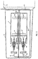
- the suction delivery device may include a pair of shell glass vials 2 and 2a connected by a pair of adaptors 4 and 4a which are in turn connected to lengths of tubing 12 and 12a.
- the tubing 12 and 12a are joined via a Y-shaped junction member (not shown).
- Each shell glass vial 2, 2a is mounted within the housing 13 on support clips 21, 21a and 21' and 21a' respectively, between detent means 22 and 22a.
- the housing 13 completely encloses the suction delivery device. Replacement of empty shell glass vials is achieved by removal of the housing from the pump body 14. The housing is then opened and the empty shell glass vials 2 and 2a detached from the adaptors 4 and 4a and replaced.
- the tubing may be sealed via an O-ring at the point where the tubing exits the pump body.
- cylindrical medicament vials are shown in vertical orientation.
- the cylindrical medicament vials may be mounted horizontally if desired.
Landscapes
- Health & Medical Sciences (AREA)
- Heart & Thoracic Surgery (AREA)
- Hematology (AREA)
- Engineering & Computer Science (AREA)
- Anesthesiology (AREA)
- Biomedical Technology (AREA)
- Life Sciences & Earth Sciences (AREA)
- Animal Behavior & Ethology (AREA)
- General Health & Medical Sciences (AREA)
- Public Health (AREA)
- Veterinary Medicine (AREA)
- Pulmonology (AREA)
- Vascular Medicine (AREA)
- Infusion, Injection, And Reservoir Apparatuses (AREA)
- Acyclic And Carbocyclic Compounds In Medicinal Compositions (AREA)
Claims (15)
- Aufbau zum Gebrauch mit Pumpmitteln (14), um eine Medikamentenabgabevorrichtung für den Gebrauch mit einem Medikamentenfläschchen (2) zu bilden, das an einem Ende durch einen durchdringbaren Kolben (7) verschlossen ist, der in das Fläschchen bewegbar ist, um das innere Volumen um einen Betrag zu reduzieren, welcher dem aus dem Fläschchen gezogenen Medikamentenvolumen entspricht, wobei der Aufbau aufweist: ein Gehäuse (13);einen vorbestimmten Fläschchenaufnahmebereich innerhalb des Gehäuses mit einer vorbestimmten Länge zur Aufnahme des Fläschchens innerhalb des Gehäuses;einen Adapter (1, 4) mit einer Verbindungsmuffe (5) für die Verbindung mit dem Kolben (7) des Fläschchens, einer Verbindungsdüse (10) für die Verbindung mit von dem Adapter führenden Rohrmitteln (12) und einer rohrförmigen Spitze (9) zum Durchdringen des Kolbens (7), wenn der Kolben mit der Verbindungsmuffe (5) verbunden ist, um dadurch das Fläschchen (2) mit einem Fluidweg in Fließverbindung zu bringen, der sich durch den Adapter erstreckt;
dadurch gekennzeichnet, daß:das Gehäuse (13) eine Druckplatte (23) aufweist, die eine Grenzfläche für ein Pumpenmittel bestimmt;
und der Aufbau ferner aufweist:Befestigungsmittel (16; 21, 21a) für die Befestigung eines Fläschchens (2) in einer im wesentlichen festen Position in dem Fläschchenaufnahmebereich innerhalb des Gehäuses;flexible Rohrmittel (12), deren eines Ende mit der Verbindungsdüse (10) gekoppelt ist, einen peristaltisch pumpbaren ersten Abschnitt (20'), der auf der Druckplatte in einer im wesentlichen festen Position bezüglich des Gehäuses (13) gestützt wird, um mit den Pumpmitteln (14) in Verbindung zu stehen, wenn das Gehäuse daran gekoppelt ist, und einen Spulenabschnitt (20) zwischen dem Ende und dem pumpbaren Abschnitt 20', um dem Adapter zu erlauben, sich bezüglich des Gehäuses (13) im wesentlichen entlang der Länge des Fläschchenaufnahmebereichs zu bewegen, wodurch im Gebrauch, wenn der Aufbau an die Pumpmittel (14) und das Fläschchen (2) gekoppelt ist, der Spulenabschnitt (20) der Rohrmittel dem Adapter (1, 4) erlaubt, sich mit dem Kolben (7) des Fläschchens in das Fläschchen zu bewegen, wenn das Medikament durch das Saugen herausgezogen wird, welches in den Rohrmitteln durch die Pumpmittel erzeugt wird. - Aufbau nach Anspruch 1, wobei das Gehäuse (13) einen hohlen Körper (15) und einen hohlen, länglichen äußeren Mantel (16) aufweist, der lösbar mit einer Basiswand (17) des hohen Körpers verbunden ist und ein geschlossenes und ein offenes Ende hat, wobei der hohle äußere Mantel aufgebaut ist, um das Medikamentenfläschchen aufzunehmen und einzuschließen.
- Aufbau nach Anspruch 1, wobei das Befestigungsmittel eine Klammer zum lösbaren Halten des Fläschchens aufweist.
- Aufbau nach Anspruch 1, 2 oder 3, der ferner einen zweiten Fläschchenadapter (1a) für die Kupplung an den Kolben eines weiteren Medikamentenfläschchens aufweist, wobei die Rohrmittel ferner eine Verbindung zwischen den ersten und zweiten Abschnitten (20', 20) des Rohres aufweisen und sich ein dritter Rohrabschnitt (20a) von der Verbindung zu dem zweiten Adapter erstreckt, um Medikamentenabgabe parallel aus zwei Fläschchen zu ermöglichen.
- Medikamentenabgabevorrichtung für den Gebrauch mit einem Medikamentenfläschchen, das an einem Ende durch einen durchdringbaren Kolben geschlossen ist, der in das Fläschchen bewegbar ist, um das innere Volumen um einen Betrag zu reduzieren, welcher dem aus dem Fläschchen gezogenen Medikamentenvolumen entspricht, wobei die Vorrichtung betriebsfähig ist, das Medikament aus dem Fläschchen abzugeben, und aufweist:ein Gehäuse (13);einen vorbestimmten Fläschchenaufnahmebereich innerhalb des Gehäuses mit einer vorbestimmten Länge für die Aufnahme des Fläschchens innerhalb des Gehäuses;einen Adapter (1, 4) mit einer Verbindungsmuffe (5) für die Verbindung mit dem Kolben (7) des Fläschchens, eine Verbindungsdüse (10) für die Verbindung mit einem von dem Adapter führenden Rohrmittel (12) und eine rohrförmige Spitze (9), um den Kolben zu durchdringen, wenn der Kolben (7) mit der Verbindungsmuffe (5) verbunden ist, um dadurch das Fläschchen (2) mit einem Fluidweg in Fließverbindung zu bringen, der sich durch den Adapter erstreckt;
gekennzeichnet durch:Befestigungsmittel (16; 21, 21a) für die Befestigung des Fläschchens (2) in einer im wesentlichen festen Position in dem Fläschchenaufnahmebereich innerhalb des Gehäuses (13);flexible Rohrmittel (12) mit einem Ende das an die Verbindungsdüse (10) gekoppelt ist, einem ersten Abschnitt (20'), der in einer im wesentlichen festen Position bezüglich des Gehäuses zurückgehalten ist, um mit einem Pumpmittel in Verbindung zu stehen, und einem zweiten Spulenabschnitt (20) zwischen dem Ende und dem ersten Abschnitt (20'), um die Bewegung des Adapters (1, 4) bezüglich des Gehäuses im wesentlichen entlang der Länge des Fläschchenaufnahmebereichs anzupassen; undPumpmittel (14), die mit dem ersten Abschnitt(20') der Rohrmittel in Verbindung stehen, um deren Pumpen durch Aufbringen von Druck auf das Äußere der Rohrmittel zu bewirken, um Medikament entlang der Rohrmittel vorwärts zu treiben;wodurch in Gebrauch der Spulenabschnitt (20) dem Adapter (1, 4) erlaubt, sich mit dem Kolben (7) des Fläschchens (2) in das Fläschchen zu bewegen, wenn Medikament durch die Tätigkeit der Pumpmittel (14) an den Rohrmitteln herausgezogen wird. - Vorrichtung nach Anspruch 5, wobei die rohrförmige Spitze ein zugespitztes freies Ende und ein Basisende aufweist, das zentral innerhalb der Muffe befestigt ist.
- Vorrichtung nach Anspruch 6, wobei die Muffe eine zylindrische Ausnehmung (5) aufweist, die Muffe ferner ein nach innen gekehrtes Schraubengewinde aufweist, um mit dem Teil des Kolbens (7) in Gewindeeingriff zu kommen, der bei Gebrauch in der Ausnehmung aufgenommen werden soll.
- Vorrichtung nach einem der Ansprüche 5 bis 7, wobei das Gehäuse (13) lösbar an den Pumpmitteln (14) befestigt ist.
- Vorrichtung nach einem der Ansprüche 5 bis 8, wobei das Gehäuse eine Druckplatte aufweist, auf welcher der erste Abschnitt des Rohres gestützt ist, und die Druckplatte eine Grenzfläche zwischen dem Gehäuse und dem Pumpmittel bildet.
- Vorrichtung nach Anspruch 8 oder 9, wobei das Gehäuse (13) einen hohlen Körper (15) und einen hohen, länglichen Außenmantel (16) aufweist, der lösbar mit einer Basiswand (17) des hohlen Körpers verbunden ist, und ein geschlossenes und ein offenes Ende hat, wobei der hohle Außenmantel so aufgebaut ist, daß er das Medikamentenfläschchen aufnimmt und einschließt.
- Vorrichtung nach einem der Ansprüche 5 bis 9, wobei das Mittel zur Befestigung des Fläschchens eine Klammer (21, 21a) aufweist.
- Vorrichtung nach einem der Ansprüche 5 bis 11 wobei das Pumpmittel eine peristaltische Pumpe (14) aufweist, die längs auf dem ersten Abschnitt (20') des Rohrmittels arbeitet, um auf diesem eine lineare Pumptätigkeit herzustellen.
- Vorrichtung nach einem der Ansprüche 5 bis 12, ferner mit einem zweiten Fläschchenadapter (1a) zum Koppeln an den Kolben eines weiteren Medikamentenfläschchens, wobei das Rohr ferner eine Verbindung zwischen den ersten und zweiten Abschnitten (20', 20) des Rohres aufweist und ein dritter Rohrabschnitt (20a) sich von der Verbindung zu dem zweiten Adapter erstreckt, um die Medikamentenabgabe parallel von zwei Fläschchen zu ermöglichen.
- Medikamentenabgabesystem mit einer Vorrichtung nach einem der Ansprüche 5 bis 13 und einem Medikamentenfläschchen (2), das an einem Ende durch einen durchdringbaren Kolben (7) geschlossen ist, der in das Fläschchen bewegbar ist, um das innere Volumen um einen Betrag zu reduzieren, welcher dem Medikamentenvolumen entspricht, das aus dem Fläschchen gezogen wurde, wobei der Kolben mit der Verbindungsmuffe des Adapters verbunden ist.
- Medikamentenabgabesystem mit einer Vorrichtung nach Anspruch 13 und ersten und zweiten Medikamentenfläschchen (2, 2a), von denen jedes an einem Ende durch einen durchdringbaren Kolben (7) verschlossen ist, der mit einem entsprechenden Adapter verbunden ist, wobei jeder Kolben in das entsprechende Fläschchen bewegbar ist, um das innere Volumen um einen Betrag zu reduzieren, welcher dem Medikamentenvolumen entspricht, das aus dem Fläschchen gezogen wurde.
Applications Claiming Priority (3)
| Application Number | Priority Date | Filing Date | Title |
|---|---|---|---|
| AU611/92 | 1992-01-30 | ||
| AUPL061192 | 1992-01-30 | ||
| AU61192 | 1992-01-30 |
Publications (2)
| Publication Number | Publication Date |
|---|---|
| EP0555007A1 EP0555007A1 (de) | 1993-08-11 |
| EP0555007B1 true EP0555007B1 (de) | 1999-12-15 |
Family
ID=3775958
Family Applications (1)
| Application Number | Title | Priority Date | Filing Date |
|---|---|---|---|
| EP93300602A Expired - Lifetime EP0555007B1 (de) | 1992-01-30 | 1993-01-28 | Medikamentenabgabesystem |
Country Status (8)
| Country | Link |
|---|---|
| US (1) | US5324258A (de) |
| EP (1) | EP0555007B1 (de) |
| AT (1) | ATE187655T1 (de) |
| CA (1) | CA2088174A1 (de) |
| DE (1) | DE69327261T2 (de) |
| NZ (1) | NZ245778A (de) |
| PT (1) | PT555007E (de) |
| SG (1) | SG43019A1 (de) |
Families Citing this family (34)
| Publication number | Priority date | Publication date | Assignee | Title |
|---|---|---|---|---|
| US5540561A (en) * | 1993-10-28 | 1996-07-30 | Sims Deltec, Inc. | Reservoir enclosure arrangements |
| US5567119A (en) * | 1993-10-28 | 1996-10-22 | Sims Deltec, Inc. | Bag/syringe enclosure arrangements and methods |
| US5879143A (en) * | 1996-04-26 | 1999-03-09 | Sims Deltec, Inc. | Reservoir enclosure adaptors and methods |
| US6186982B1 (en) | 1998-05-05 | 2001-02-13 | Elan Corporation, Plc | Subcutaneous drug delivery device with improved filling system |
| US6500150B1 (en) | 1997-06-16 | 2002-12-31 | Elan Pharma International Limited | Pre-filled drug-delivery device and method of manufacture and assembly of same |
| US6551298B1 (en) * | 2000-11-21 | 2003-04-22 | Jack Y. Zhang | Controlled medicament security enclosure system |
| US6610036B2 (en) | 2001-02-06 | 2003-08-26 | Vista Innovations, Inc. | Eye drop dispensing system |
| EP1511528A4 (de) * | 2002-05-16 | 2008-07-02 | Scott Lab Inc | Arzneimittelbehälter-eingangsmechanismen und verfahren |
| US20050159708A1 (en) * | 2002-07-24 | 2005-07-21 | Rudolf Sidler | Infusion pump, control program, semiconductor means and method for the dosed administration of a medicinal liquid |
| EP1639286B1 (de) * | 2003-06-17 | 2014-12-03 | Filtertek Inc. | Fluidhandhabungsvorrichtung |
| US7806265B2 (en) * | 2006-07-12 | 2010-10-05 | Mobius Therapeutics, Llc | Apparatus and method for reconstituting a pharmaceutical and preparing the reconstituted pharmaceutical for transient application |
| US9539241B2 (en) | 2006-07-12 | 2017-01-10 | Mobius Therapeutics, Llc | Apparatus and method for reconstituting a pharmaceutical and preparing the reconstituted pharmaceutical for transient application |
| US9205075B2 (en) | 2006-07-12 | 2015-12-08 | Mobius Therapeutics, Llc | Apparatus and method for reconstituting a pharmaceutical and preparing the reconstituted pharmaceutical for transient application |
| US20080119782A1 (en) * | 2006-10-25 | 2008-05-22 | Steinman Christopher P | Method for delivering solutions to a patient |
| US8545440B2 (en) | 2007-12-21 | 2013-10-01 | Carticept Medical, Inc. | Injection system for delivering multiple fluids within the anatomy |
| EP2231230A4 (de) * | 2007-12-21 | 2013-01-23 | Carticept Medical Inc | Gelenkinjektionssystem |
| US9044542B2 (en) | 2007-12-21 | 2015-06-02 | Carticept Medical, Inc. | Imaging-guided anesthesia injection systems and methods |
| MX2012000100A (es) | 2009-07-01 | 2012-04-02 | Fresenius Med Care Hldg Inc | Dispositivos de suministro de farmaco y sistemas y metodos relacionados. |
| CA2786013C (en) * | 2010-01-29 | 2018-08-07 | Kci Licensing, Inc. | Systems and methods for positioning fluid supply system |
| CA2812774A1 (en) | 2010-10-01 | 2012-04-05 | Zevex, Inc. | Method for improving accuracy in a peristaltic pump system based on tubing material properties |
| EP2671176B1 (de) | 2011-01-31 | 2019-01-09 | Fresenius Medical Care Holdings, Inc. | Verhinderung von übermässiger freisetzung eines arzneistoffs |
| EP2673018B1 (de) | 2011-02-08 | 2019-04-10 | Fresenius Medical Care Holdings, Inc. | Magnetische sensoren und zugehörige systeme und verfahren |
| WO2013119482A1 (en) * | 2012-02-06 | 2013-08-15 | Michael Friedman | Apparatus and methods for controlled delivery of heated fluids to a subject |
| US9144646B2 (en) | 2012-04-25 | 2015-09-29 | Fresenius Medical Care Holdings, Inc. | Vial spiking devices and related assemblies and methods |
| US9987416B2 (en) | 2015-01-09 | 2018-06-05 | BioQuiddity Inc. | Sterile assembled liquid medicament dosage control and delivery device |
| ES2985905T3 (es) | 2016-11-22 | 2024-11-07 | Lts Device Tech Ltd | Aparato para suministrar una sustancia terapéutica |
| US10994116B2 (en) | 2018-06-30 | 2021-05-04 | Bioq Pharma Incorporated | Drug cartridge-based infusion pump |
| EP3632487B1 (de) | 2018-10-05 | 2024-06-12 | LTS Device Technologies Ltd | Auslösesequenz |
| EP3924014B1 (de) * | 2019-02-12 | 2024-10-16 | Amgen Inc. | System zur verabreichung von medikamenten zuhause |
| US11338082B2 (en) | 2019-09-04 | 2022-05-24 | BloQ Pharma, Inc. | Variable rate dispenser with aseptic spike connector assembly |
| CN110687102B (zh) * | 2019-10-10 | 2022-03-01 | 四川轻化工大学 | 一种供液集液组件及其气液相化学发光检测系统 |
| WO2022224656A1 (ja) * | 2021-04-22 | 2022-10-27 | 京セラ株式会社 | 筒体キットおよびガスケット |
| MX2023013113A (es) | 2021-07-01 | 2024-02-09 | Kairish Innotech Private Ltd | Dispensador de liquido por bombeo que incluye un adaptador para vial. |
| US11957326B2 (en) * | 2022-04-19 | 2024-04-16 | Ethicon, Inc. | Variable length telescoping application tips for flowable hemostats and sealants application |
Family Cites Families (13)
| Publication number | Priority date | Publication date | Assignee | Title |
|---|---|---|---|---|
| US3321098A (en) * | 1965-06-29 | 1967-05-23 | Safti Vial Corp | Vial |
| BE759374A (fr) * | 1970-06-08 | 1971-04-30 | Ims Ltd | Emballage pour medicament |
| US3994296A (en) * | 1972-08-10 | 1976-11-30 | Nosco Plastics, Inc. | Syringe |
| CA1015237A (en) * | 1972-09-20 | 1977-08-09 | Harold S. Cloyd | Syringe |
| US4199307A (en) * | 1977-07-05 | 1980-04-22 | Andros Incorporated | Medical infusion system |
| US4169475A (en) * | 1977-12-08 | 1979-10-02 | Abbott Laboratories | Additive transfer unit |
| FI67024C (fi) * | 1982-09-01 | 1985-01-10 | Labsystems Oy | Anordning foer subkutan dosering av laekemedel |
| US4657486A (en) * | 1984-01-13 | 1987-04-14 | Stempfle Julius E | Portable infusion device |
| US4650469A (en) * | 1984-10-19 | 1987-03-17 | Deltec Systems, Inc. | Drug delivery system |
| US4559038A (en) * | 1984-10-19 | 1985-12-17 | Deltec Systems, Inc. | Drug delivery system |
| US4565542A (en) * | 1984-10-19 | 1986-01-21 | Deltec Systems, Inc. | Locking mechanism for a drug delivery system |
| US4662878A (en) * | 1985-11-13 | 1987-05-05 | Patents Unlimited Ltd. | Medicine vial adaptor for needleless injector |
| IT217359Z2 (it) * | 1989-06-20 | 1991-12-03 | Tomellini Giorgio E Rollandi G | Dispositivo di somministrazione di farmaci |
-
1993
- 1993-01-22 US US08/007,619 patent/US5324258A/en not_active Expired - Fee Related
- 1993-01-27 CA CA002088174A patent/CA2088174A1/en not_active Abandoned
- 1993-01-28 PT PT93300602T patent/PT555007E/pt unknown
- 1993-01-28 AT AT93300602T patent/ATE187655T1/de not_active IP Right Cessation
- 1993-01-28 DE DE69327261T patent/DE69327261T2/de not_active Expired - Fee Related
- 1993-01-28 EP EP93300602A patent/EP0555007B1/de not_active Expired - Lifetime
- 1993-01-28 SG SG1996002534A patent/SG43019A1/en unknown
- 1993-01-28 NZ NZ245778A patent/NZ245778A/en unknown
Also Published As
| Publication number | Publication date |
|---|---|
| DE69327261D1 (de) | 2000-01-20 |
| EP0555007A1 (de) | 1993-08-11 |
| CA2088174A1 (en) | 1993-07-31 |
| US5324258A (en) | 1994-06-28 |
| DE69327261T2 (de) | 2000-08-03 |
| PT555007E (pt) | 2000-06-30 |
| SG43019A1 (en) | 1997-10-17 |
| NZ245778A (en) | 1995-12-21 |
| ATE187655T1 (de) | 2000-01-15 |
Similar Documents
| Publication | Publication Date | Title |
|---|---|---|
| EP0555007B1 (de) | Medikamentenabgabesystem | |
| US8840586B2 (en) | Systems and methods allowing for reservoir filling and infusion medium delivery | |
| US7794434B2 (en) | Systems and methods allowing for reservoir filling and infusion medium delivery | |
| US5032117A (en) | Tandem syringe | |
| US7828764B2 (en) | Systems and methods allowing for reservoir filling and infusion medium delivery | |
| US7811262B2 (en) | Systems and methods allowing for reservoir filling and infusion medium delivery | |
| US8393357B2 (en) | Reservoir filling systems and methods | |
| EP2061536B1 (de) | Systeme und verfahren zur füllung von behältern und zur ausgabe eines infusionsmediums | |
| US8356645B2 (en) | Transfer guard systems and methods | |
| US5135500A (en) | Self-driven pump device | |
| EP0577354B1 (de) | Spritzenantriebseinrichtung | |
| US8512289B2 (en) | Reservoir filling systems and methods | |
| US20080051765A1 (en) | Systems and methods allowing for reservoir filling and infusion medium delivery | |
| US6245041B1 (en) | Fluid dispenser with fill adapter | |
| US5624407A (en) | Medication injecting device and accessories therefor | |
| US8142398B1 (en) | Fluid dispenser | |
| AU657074B2 (en) | Drug delivery system | |
| JPH0313908B2 (de) | ||
| JPS61234872A (ja) | 使捨て可能な貯溜カセツト |
Legal Events
| Date | Code | Title | Description |
|---|---|---|---|
| PUAI | Public reference made under article 153(3) epc to a published international application that has entered the european phase |
Free format text: ORIGINAL CODE: 0009012 |
|
| AK | Designated contracting states |
Kind code of ref document: A1 Designated state(s): AT BE CH DE DK ES FR GB GR IE IT LI LU MC NL PT SE |
|
| 17P | Request for examination filed |
Effective date: 19940203 |
|
| RAP1 | Party data changed (applicant data changed or rights of an application transferred) |
Owner name: F.H. FAULDING & CO. LIMITED |
|
| 17Q | First examination report despatched |
Effective date: 19950322 |
|
| GRAG | Despatch of communication of intention to grant |
Free format text: ORIGINAL CODE: EPIDOS AGRA |
|
| GRAG | Despatch of communication of intention to grant |
Free format text: ORIGINAL CODE: EPIDOS AGRA |
|
| GRAH | Despatch of communication of intention to grant a patent |
Free format text: ORIGINAL CODE: EPIDOS IGRA |
|
| GRAH | Despatch of communication of intention to grant a patent |
Free format text: ORIGINAL CODE: EPIDOS IGRA |
|
| GRAA | (expected) grant |
Free format text: ORIGINAL CODE: 0009210 |
|
| AK | Designated contracting states |
Kind code of ref document: B1 Designated state(s): AT BE CH DE DK ES FR GB GR IE IT LI LU MC NL PT SE |
|
| PG25 | Lapsed in a contracting state [announced via postgrant information from national office to epo] |
Ref country code: SE Free format text: THE PATENT HAS BEEN ANNULLED BY A DECISION OF A NATIONAL AUTHORITY Effective date: 19991215 Ref country code: NL Free format text: LAPSE BECAUSE OF FAILURE TO SUBMIT A TRANSLATION OF THE DESCRIPTION OR TO PAY THE FEE WITHIN THE PRESCRIBED TIME-LIMIT Effective date: 19991215 Ref country code: LI Free format text: LAPSE BECAUSE OF FAILURE TO SUBMIT A TRANSLATION OF THE DESCRIPTION OR TO PAY THE FEE WITHIN THE PRESCRIBED TIME-LIMIT Effective date: 19991215 Ref country code: GR Free format text: LAPSE BECAUSE OF NON-PAYMENT OF DUE FEES Effective date: 19991215 Ref country code: ES Free format text: THE PATENT HAS BEEN ANNULLED BY A DECISION OF A NATIONAL AUTHORITY Effective date: 19991215 Ref country code: CH Free format text: LAPSE BECAUSE OF FAILURE TO SUBMIT A TRANSLATION OF THE DESCRIPTION OR TO PAY THE FEE WITHIN THE PRESCRIBED TIME-LIMIT Effective date: 19991215 Ref country code: AT Free format text: LAPSE BECAUSE OF FAILURE TO SUBMIT A TRANSLATION OF THE DESCRIPTION OR TO PAY THE FEE WITHIN THE PRESCRIBED TIME-LIMIT Effective date: 19991215 |
|
| REF | Corresponds to: |
Ref document number: 187655 Country of ref document: AT Date of ref document: 20000115 Kind code of ref document: T |
|
| REG | Reference to a national code |
Ref country code: CH Ref legal event code: EP |
|
| REF | Corresponds to: |
Ref document number: 69327261 Country of ref document: DE Date of ref document: 20000120 |
|
| PG25 | Lapsed in a contracting state [announced via postgrant information from national office to epo] |
Ref country code: LU Free format text: LAPSE BECAUSE OF NON-PAYMENT OF DUE FEES Effective date: 20000128 |
|
| PG25 | Lapsed in a contracting state [announced via postgrant information from national office to epo] |
Ref country code: MC Free format text: THE PATENT HAS BEEN ANNULLED BY A DECISION OF A NATIONAL AUTHORITY Effective date: 20000215 |
|
| REG | Reference to a national code |
Ref country code: IE Ref legal event code: FG4D |
|
| PGFP | Annual fee paid to national office [announced via postgrant information from national office to epo] |
Ref country code: PT Payment date: 20000313 Year of fee payment: 8 |
|
| ITF | It: translation for a ep patent filed | ||
| PG25 | Lapsed in a contracting state [announced via postgrant information from national office to epo] |
Ref country code: DK Free format text: LAPSE BECAUSE OF FAILURE TO SUBMIT A TRANSLATION OF THE DESCRIPTION OR TO PAY THE FEE WITHIN THE PRESCRIBED TIME-LIMIT Effective date: 20000315 |
|
| PGFP | Annual fee paid to national office [announced via postgrant information from national office to epo] |
Ref country code: FR Payment date: 20000329 Year of fee payment: 8 Ref country code: DE Payment date: 20000329 Year of fee payment: 8 Ref country code: BE Payment date: 20000329 Year of fee payment: 8 |
|
| ET | Fr: translation filed | ||
| NLV1 | Nl: lapsed or annulled due to failure to fulfill the requirements of art. 29p and 29m of the patents act | ||
| REG | Reference to a national code |
Ref country code: CH Ref legal event code: PL |
|
| REG | Reference to a national code |
Ref country code: PT Ref legal event code: SC4A Free format text: AVAILABILITY OF NATIONAL TRANSLATION Effective date: 20000313 |
|
| PLBE | No opposition filed within time limit |
Free format text: ORIGINAL CODE: 0009261 |
|
| 26N | No opposition filed | ||
| PGFP | Annual fee paid to national office [announced via postgrant information from national office to epo] |
Ref country code: IE Payment date: 20001206 Year of fee payment: 9 |
|
| PG25 | Lapsed in a contracting state [announced via postgrant information from national office to epo] |
Ref country code: BE Free format text: LAPSE BECAUSE OF NON-PAYMENT OF DUE FEES Effective date: 20010131 |
|
| BERE | Be: lapsed |
Owner name: F.H. FAULDING & CO. LTD Effective date: 20010131 |
|
| PG25 | Lapsed in a contracting state [announced via postgrant information from national office to epo] |
Ref country code: PT Free format text: LAPSE BECAUSE OF NON-PAYMENT OF DUE FEES Effective date: 20010731 |
|
| PG25 | Lapsed in a contracting state [announced via postgrant information from national office to epo] |
Ref country code: FR Free format text: LAPSE BECAUSE OF NON-PAYMENT OF DUE FEES Effective date: 20010928 |
|
| PG25 | Lapsed in a contracting state [announced via postgrant information from national office to epo] |
Ref country code: DE Free format text: LAPSE BECAUSE OF NON-PAYMENT OF DUE FEES Effective date: 20011101 |
|
| REG | Reference to a national code |
Ref country code: FR Ref legal event code: ST |
|
| REG | Reference to a national code |
Ref country code: PT Ref legal event code: MM4A Free format text: LAPSE DUE TO NON-PAYMENT OF FEES Effective date: 20010731 |
|
| REG | Reference to a national code |
Ref country code: GB Ref legal event code: IF02 |
|
| PGFP | Annual fee paid to national office [announced via postgrant information from national office to epo] |
Ref country code: GB Payment date: 20020109 Year of fee payment: 10 |
|
| PG25 | Lapsed in a contracting state [announced via postgrant information from national office to epo] |
Ref country code: IE Free format text: LAPSE BECAUSE OF NON-PAYMENT OF DUE FEES Effective date: 20020128 |
|
| REG | Reference to a national code |
Ref country code: GB Ref legal event code: 732E |
|
| REG | Reference to a national code |
Ref country code: IE Ref legal event code: MM4A |
|
| PG25 | Lapsed in a contracting state [announced via postgrant information from national office to epo] |
Ref country code: GB Free format text: LAPSE BECAUSE OF NON-PAYMENT OF DUE FEES Effective date: 20030128 |
|
| GBPC | Gb: european patent ceased through non-payment of renewal fee | ||
| PG25 | Lapsed in a contracting state [announced via postgrant information from national office to epo] |
Ref country code: IT Free format text: LAPSE BECAUSE OF NON-PAYMENT OF DUE FEES;WARNING: LAPSES OF ITALIAN PATENTS WITH EFFECTIVE DATE BEFORE 2007 MAY HAVE OCCURRED AT ANY TIME BEFORE 2007. THE CORRECT EFFECTIVE DATE MAY BE DIFFERENT FROM THE ONE RECORDED. Effective date: 20050128 |