EP0555105B1 - Instrument de chirurgie endoscopique ayant des effecteurs terminaux pivotables - Google Patents
Instrument de chirurgie endoscopique ayant des effecteurs terminaux pivotables Download PDFInfo
- Publication number
- EP0555105B1 EP0555105B1 EP93300906A EP93300906A EP0555105B1 EP 0555105 B1 EP0555105 B1 EP 0555105B1 EP 93300906 A EP93300906 A EP 93300906A EP 93300906 A EP93300906 A EP 93300906A EP 0555105 B1 EP0555105 B1 EP 0555105B1
- Authority
- EP
- European Patent Office
- Prior art keywords
- push rod
- bore
- tube
- handle
- relative
- Prior art date
- Legal status (The legal status is an assumption and is not a legal conclusion. Google has not performed a legal analysis and makes no representation as to the accuracy of the status listed.)
- Expired - Lifetime
Links
- 239000012636 effector Substances 0.000 title claims abstract description 64
- 230000033001 locomotion Effects 0.000 claims abstract description 44
- 238000007373 indentation Methods 0.000 claims 1
- 230000000694 effects Effects 0.000 abstract description 3
- 229910052751 metal Inorganic materials 0.000 description 46
- 239000002184 metal Substances 0.000 description 46
- 230000007246 mechanism Effects 0.000 description 27
- 230000008878 coupling Effects 0.000 description 9
- 238000010168 coupling process Methods 0.000 description 9
- 238000005859 coupling reaction Methods 0.000 description 9
- 230000002093 peripheral effect Effects 0.000 description 9
- 230000013011 mating Effects 0.000 description 8
- 238000000034 method Methods 0.000 description 8
- 230000009471 action Effects 0.000 description 4
- 229910052782 aluminium Inorganic materials 0.000 description 4
- XAGFODPZIPBFFR-UHFFFAOYSA-N aluminium Chemical compound [Al] XAGFODPZIPBFFR-UHFFFAOYSA-N 0.000 description 4
- 210000005224 forefinger Anatomy 0.000 description 4
- 238000003780 insertion Methods 0.000 description 4
- 230000037431 insertion Effects 0.000 description 4
- 210000003811 finger Anatomy 0.000 description 3
- 238000002357 laparoscopic surgery Methods 0.000 description 3
- 239000000463 material Substances 0.000 description 3
- 210000000056 organ Anatomy 0.000 description 3
- 210000003813 thumb Anatomy 0.000 description 3
- 210000003815 abdominal wall Anatomy 0.000 description 2
- 230000004913 activation Effects 0.000 description 2
- 230000008859 change Effects 0.000 description 2
- 230000006835 compression Effects 0.000 description 2
- 238000007906 compression Methods 0.000 description 2
- 238000010276 construction Methods 0.000 description 2
- 238000001839 endoscopy Methods 0.000 description 2
- 239000004033 plastic Substances 0.000 description 2
- 229910001220 stainless steel Inorganic materials 0.000 description 2
- 239000010935 stainless steel Substances 0.000 description 2
- 238000001356 surgical procedure Methods 0.000 description 2
- 229910001369 Brass Inorganic materials 0.000 description 1
- 238000004026 adhesive bonding Methods 0.000 description 1
- 230000005540 biological transmission Effects 0.000 description 1
- 239000010951 brass Substances 0.000 description 1
- 238000002788 crimping Methods 0.000 description 1
- 238000010586 diagram Methods 0.000 description 1
- 230000003292 diminished effect Effects 0.000 description 1
- 238000006073 displacement reaction Methods 0.000 description 1
- 230000002708 enhancing effect Effects 0.000 description 1
- 210000000232 gallbladder Anatomy 0.000 description 1
- 230000036512 infertility Effects 0.000 description 1
- 230000004048 modification Effects 0.000 description 1
- 238000012986 modification Methods 0.000 description 1
- 239000002991 molded plastic Substances 0.000 description 1
- 210000001672 ovary Anatomy 0.000 description 1
- 238000005192 partition Methods 0.000 description 1
- 230000008569 process Effects 0.000 description 1
- 230000000452 restraining effect Effects 0.000 description 1
- 230000001954 sterilising effect Effects 0.000 description 1
- 210000004291 uterus Anatomy 0.000 description 1
- 210000001835 viscera Anatomy 0.000 description 1
Images





Classifications
-
- A—HUMAN NECESSITIES
- A61—MEDICAL OR VETERINARY SCIENCE; HYGIENE
- A61B—DIAGNOSIS; SURGERY; IDENTIFICATION
- A61B17/00—Surgical instruments, devices or methods
- A61B17/28—Surgical forceps
- A61B17/29—Forceps for use in minimally invasive surgery
-
- A—HUMAN NECESSITIES
- A61—MEDICAL OR VETERINARY SCIENCE; HYGIENE
- A61B—DIAGNOSIS; SURGERY; IDENTIFICATION
- A61B18/00—Surgical instruments, devices or methods for transferring non-mechanical forms of energy to or from the body
- A61B18/04—Surgical instruments, devices or methods for transferring non-mechanical forms of energy to or from the body by heating
- A61B18/12—Surgical instruments, devices or methods for transferring non-mechanical forms of energy to or from the body by heating by passing a current through the tissue to be heated, e.g. high-frequency current
- A61B18/14—Probes or electrodes therefor
- A61B18/1442—Probes having pivoting end effectors, e.g. forceps
-
- A—HUMAN NECESSITIES
- A61—MEDICAL OR VETERINARY SCIENCE; HYGIENE
- A61B—DIAGNOSIS; SURGERY; IDENTIFICATION
- A61B17/00—Surgical instruments, devices or methods
- A61B2017/0046—Surgical instruments, devices or methods with a releasable handle; with handle and operating part separable
-
- A—HUMAN NECESSITIES
- A61—MEDICAL OR VETERINARY SCIENCE; HYGIENE
- A61B—DIAGNOSIS; SURGERY; IDENTIFICATION
- A61B17/00—Surgical instruments, devices or methods
- A61B17/28—Surgical forceps
- A61B17/2812—Surgical forceps with a single pivotal connection
- A61B17/2833—Locking means
- A61B2017/2837—Locking means with a locking ratchet
-
- A—HUMAN NECESSITIES
- A61—MEDICAL OR VETERINARY SCIENCE; HYGIENE
- A61B—DIAGNOSIS; SURGERY; IDENTIFICATION
- A61B17/00—Surgical instruments, devices or methods
- A61B17/28—Surgical forceps
- A61B17/29—Forceps for use in minimally invasive surgery
- A61B17/2909—Handles
- A61B2017/2912—Handles transmission of forces to actuating rod or piston
- A61B2017/2919—Handles transmission of forces to actuating rod or piston details of linkages or pivot points
- A61B2017/292—Handles transmission of forces to actuating rod or piston details of linkages or pivot points connection of actuating rod to handle, e.g. ball end in recess
-
- A—HUMAN NECESSITIES
- A61—MEDICAL OR VETERINARY SCIENCE; HYGIENE
- A61B—DIAGNOSIS; SURGERY; IDENTIFICATION
- A61B17/00—Surgical instruments, devices or methods
- A61B17/28—Surgical forceps
- A61B17/29—Forceps for use in minimally invasive surgery
- A61B2017/2926—Details of heads or jaws
- A61B2017/2927—Details of heads or jaws the angular position of the head being adjustable with respect to the shaft
-
- A—HUMAN NECESSITIES
- A61—MEDICAL OR VETERINARY SCIENCE; HYGIENE
- A61B—DIAGNOSIS; SURGERY; IDENTIFICATION
- A61B17/00—Surgical instruments, devices or methods
- A61B17/28—Surgical forceps
- A61B17/29—Forceps for use in minimally invasive surgery
- A61B2017/2926—Details of heads or jaws
- A61B2017/2927—Details of heads or jaws the angular position of the head being adjustable with respect to the shaft
- A61B2017/2929—Details of heads or jaws the angular position of the head being adjustable with respect to the shaft with a head rotatable about the longitudinal axis of the shaft
-
- A—HUMAN NECESSITIES
- A61—MEDICAL OR VETERINARY SCIENCE; HYGIENE
- A61B—DIAGNOSIS; SURGERY; IDENTIFICATION
- A61B17/00—Surgical instruments, devices or methods
- A61B17/28—Surgical forceps
- A61B17/29—Forceps for use in minimally invasive surgery
- A61B2017/2926—Details of heads or jaws
- A61B2017/2927—Details of heads or jaws the angular position of the head being adjustable with respect to the shaft
- A61B2017/2929—Details of heads or jaws the angular position of the head being adjustable with respect to the shaft with a head rotatable about the longitudinal axis of the shaft
- A61B2017/293—Details of heads or jaws the angular position of the head being adjustable with respect to the shaft with a head rotatable about the longitudinal axis of the shaft with means preventing relative rotation between the shaft and the actuating rod
-
- A—HUMAN NECESSITIES
- A61—MEDICAL OR VETERINARY SCIENCE; HYGIENE
- A61B—DIAGNOSIS; SURGERY; IDENTIFICATION
- A61B17/00—Surgical instruments, devices or methods
- A61B17/28—Surgical forceps
- A61B17/29—Forceps for use in minimally invasive surgery
- A61B2017/2926—Details of heads or jaws
- A61B2017/2932—Transmission of forces to jaw members
- A61B2017/2939—Details of linkages or pivot points
Definitions
- the present invention broadly relates to endoscopic surgical instruments. More particularly, the invention relates to disposable endoscopic instruments having end effectors and actuation means for effecting movement of the end effectors where the end effectors are rotatable relative to the actuation means as specified in the preamble of Claim 1.
- Such an instrument is known e.g. from DE-U-9007356.
- the endoscopy and laparoscopy procedures have recently become widely practiced surgical procedures.
- the endoscopy and laparoscopy procedures involve incising through body walls (e.g., such as the abdominal wall) for examining, viewing and/or operating on the ovaries, uterus, gall bladder, bowels, appendix, etc.
- body walls e.g., such as the abdominal wall
- trocars are utilized for creating the incisions.
- Trocar tubes are left in place in the abdominal wall so that the endoscopic or laparoscopic surgical tools may be inserted through the tube.
- a camera or magnifying lens is often inserted through a relatively large diameter trocar tube (e.g.
- a cutter, dissector, extractor, or other surgical instrument is inserted through a typically smaller diameter trocar tube (e.g. 5 mm diameter) for purposes of manipulating and/or cutting the internal organ.
- a typically smaller diameter trocar tube e.g. 5 mm diameter
- organ or tissue may be grasped with one surgical instrument, and simultaneously may be cut or stitched with another surgical instrument; all under view of the surgeon via the camera in place in the navel trocar tube.
- the endoscopic and laparoscopic tools of the prior art are primarily reusable stainless steel tools. Between each use of a stainless steel tool, the tool must be soaked, scrubbed, and disinfected. The usual procedure is then to dry the tool, wrap it, and put it in a steam autoclave. The tool is kept sterile until just prior to use when it is removed from the autoclave and unwrapped in the locale of the sterile field of use.
- actuating apparatus usually a handle and lever arrangement
- the actuating apparatus can be rotated about the longitudinal axis of the instrument relative to the end effector thus enhancing the usefulness of the instrument in surgical procedures.
- DE-U-9007356 discloses a medical instrument which may be described as comprising:
- the grip means is provided with an electrically conductive electrode having a first end extending through the grip means, the contract element being electrically conductive and being the second end of the electrode.
- a sleeve means comprising the actuating apparatus surrounds a proximal portion of the tube, and is movable along the longitudinal axis of the tube.
- the handle means surrounds the proximal end of the tube.
- the lever arm is pivotally engaged to the handle means and is also positioned at the proximal end portion of the tube.
- the sleeve means (at its proximal end) and the handle means (at its distal end) have opposing rim portions with respective mating surface configurations.
- the sleeve means is resiliently held in mating engagement with the handle means by a resilient means coupled to the sleeve and to the tube.
- the sleeve member When it is desired to change the rotational orientation of the end effector means relative to the actuating apparatus, the sleeve member is moved axially along the tube away from the handle member, against the restraining force exerted by the resilient means. Such movement disengages the mating portions of the sleeve and the handle member and leaves the sleeve free to rotate with the metal tube, and clevis means, and the end effectors relative to the handle means and the lever arm.
- three hundred sixty degree rotation is available, and the resolution to which rotation may be obtained is only limited by the resolution of the mating portions of the sleeve and handle; i.e. the finer the teeth and grooves of each, the finer the resolution.
- a rotating push rod engaging element is provided in the lever arm to couple the lever arm and the push rod.
- the rotating push rod engaging element is preferably generally spherical with a hole along a first axis for the push rod, and a hole along a second perpendicular axis for a set screw.
- the rotating push rod engaging element sits in a recess of the lever arm and rotates with the push rod, the outer tube, the end effectors etc., when they are rotated relative to the handle means and the lever arm.
- the actuating apparatus is preferably provided with a ratchet mechanism for adjustably holding the end effectors in a plurality of predetermined positions.
- the ratchet mechanism includes a resilient member, suitably in the form of a metal strip, attached at a first end, i.e. cantilevered, to either the handle means or the lever arm of the actuating apparatus, with the second end of the resilient member having a locking element for engagement with one of a tandem array of teeth positioned on an elongate member which extends from the other of said handle member or lever arm.
- a cammed latching means is provided adjacent the cantilevered end of the resilient strip to resiliently displace the resilient strip so as to engage the locking element of the resilient strip with the teeth. Because the teeth and locking element are angled, activation of the cammed latching means permits movement of the lever arm towards the handle, but does not permit movement of the lever arm away from the handle. Release of the latching means permits disengagement.
- a disposable endoscopic or laparoscopic surgical instrument is indicated at 10.
- the disposable surgical instrument 10 broadly comprises an aluminum tube 20 having a longitudinal axis 185, end effectors 22, 24, a clevis means 30, actuating apparatus 50, and a push rod 60.
- the clevis means 30 is advantageously a separately formed aluminum piece which fixedly engages aluminum tube 20 at the distal end 21 of the aluminum tube, e.g., by crimping of tube 20 as indicated at 32.
- distal end of the instrument 10 or any part thereof is the end closest to the surgical site and distant from the surgeon, while the “proximal end” of the instrument 10 or any part thereof, is the end most proximate the surgeon and distant the surgical site.
- the clevis 30 also engages the end effectors 22, 24 at pivot pin or screw 40, as the end effectors pivot around the pivot pin 40.
- the end effectors are also coupled at their proximal ends to the distal end of push rod 60 via coupling elements 62, 64.
- the clevis effectively translates the reciprocal motion (shown as 65) of the push rod 60 into the end effector means action indicated at 67, 68.
- metal tube 20 is provided with an insulating plastic shrink wrap layer 97 which provides protection when electrical energy is applied at terminal 99, e.g. for cauterization procedures.
- end effector elements 22, 24 are of the grasper type.
- the invention applies to any single or double acting instruments which are intended for insertion through a trocar tube.
- different types of end effectors can be utilized.
- different embodiments of the coupling elements, the clevis means, and the push rod as described in the parent applications hereto may be utilized in conjunction with the preferred aspects of the present invention.
- Figure 2a shows end effectors 22, 24 in a closed position
- Figure 2b is a front elevation view of the configuration of Figure 2a showing the actuating mechanism 50 (in phantom) which is more fully illustrated in Figure 1b and described hereinbelow.
- the reciprocal motion 65 of push rod 60 is effected by the lever action motion 70 of lever arm 75, of the actuating apparatus 50, which is pivotally engaged by means of pivot rod 80 to handle member 85.
- Handle member 85 and lever arm 75 are configured for one-hand operation as shown.
- the orientation of the actuating apparatus 50 i.e. handle 85 and lever arm 75, with respect to end effectors 22, 24 was fixed. That is, if a surgeon desired to rotate the handle and lever arm to a more convenient position, the end effectors 22, 24 would also be rotated correspondingly.
- the actuating apparatus 50 can be rotated to any convenient orientation, and back and forth, through 360°, without causing any rotational movement of the end effectors 22, 24.
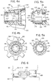
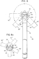
- the details of the actuating apparatus which permit rotation according to a first preferred embodiment are more fully understood with reference to Figures 1b, 3, 4a, 4b, 5a, 5b, and 6.
- the actuating apparatus generally comprises a sleeve (ferrule) member 90, the handle means 85 and the lever arm 75.
- the sleeve member 90 surrounds a portion of metal tube 20 which is remote from the end effectors 22, 24, and which is just forwardly adjacent the proximal end 23 of metal tube 20.
- sleeve member 90 is movable axially back and forth along metal tube 20 as indicated at 101 of Fig. 3.
- sleeve member 90 is restrained in its movement by a resilient spring or biasing means 103.
- Resilient spring 103 is shown as a coil spring peripherally surrounding metal tube 20 and seated in an inner peripheral slot or undercut section 105 of sleeve 90.
- the resilient spring 103 is held in compression by a retaining ring 107 and an inwardly projecting portion 95 of the sleeve member 90.
- the retaining ring 107 is seated in peripheral slot 109 of metal tube 20.
- the retaining ring 107 can be fixedly engaged to the metal tube 20 in the absence of such a peripheral slot.
- metal tube 20 is preferably provided with a plurality of axially extending peripherally spaced apart disposed slots 145 (although only one such slot is required) in a portion of the tube 20 surrounded by sleeve 90.
- One or more guide rods or inwardly extending protrusions 150 are seated in sleeve 90 and extend therethrough to slideably engage the axial slots 145. With the aforedescribed mating engagement (indicated as 140), sleeve 90 is restrained from rotation about metal tube 20, but is movable axially as indicated at 101 in Figure 1b and Figure 3.
- sleeve 90 has an engagement configuration 111 in the form of an integral peripheral proximal rim 114 of toothlike elements 113 and slots 115.
- the engagement configuration 111 is preferably enclosed by a flange portion 117 of sleeve 90 which extends around toothlike elements 113 and slots 115.
- Flange portion 117 preferably includes a series of ribs 138 which are circumferentially placed around the sleeve 90, which run in a manner substantially parallel the longitudinal axis of the surgical instrument, and which permit easy manipulation with the forefinger of the practitioner.
- the ribs 138 preferably taper downward as they extend toward the distal end of the sleeve 90.
- handle member 85 has a hollow distal portion 120 in the form of a bore coaxial with metal tube 20. Attached internally to the distal portion of handle 85 is a ring 124 which extends loosely around the tube 20. Ring 124 has a peripheral outer surface portion 122, (shown in Figures 5a and 5b) having integral ribs 123 which engage and are preferably sealed (e.g., by gluing) in slots 126 of hollow-bore portion 120 of handle 85. Thus, ring 124 is fixed relative to the handle 85. In order to prevent handle 85 from sliding off the proximal end of tube 20, a retaining ring 160 is provided.
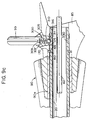
- Retaining ring 160 is seated in slot 165 of metal tube 20 and sits adjacent the proximal end of ring 124 (and in slot 170 of handle member 85 as shown best in Fig. 9). As aforementioned, metal tube 20 is free to rotate in ring 124 as it is only slideably engaged therewith and slightly spaced therefrom as indicated at 175.
- Ring 124 of handle member 85 has an engagement configuration 130 corresponding to engagement configuration 111 of sleeve 90 in the form of toothlike elements 133 and slots 135.
- toothlike elements 133 and slots 135 matingly engage (as indicated at 140 in Figure 1b) the teeth 113 and slots 115 of sleeve 90 due to the force exerted by resilient coil spring 103 on sleeve 90 toward the proximal end 23 of metal tube 20.
- a force 137 is applied to the outward radially extending ribs 138 of sleeve 90, the teeth 113 and slots 115 are disengaged from the teeth 133 and slots 135 of the handle member 85.
- metal tube 20 which is slidably engaged with the handle member 85 is free to rotate relative to the handle member.
- a first embodiment of a push rod coupling means is shown for accomplishing the relative rotation.
- the push rod coupling means is shown as a generally spherically surfaced element 190.
- Spherical element 190 is coaxial to push rod 60 and includes a diametrically located bore 191 through which push rod 60 extends.
- Push rod 60 is coupled to the spherical element 190 suitably by means of a recessed set screw 192 which threadably engages spherically surfaced element 190 and bears against and frictionally engages push rod 60 at 194.
- the lever arm 75 is provided with a cylindrical bore 200.
- Bore 200 is parallel to pivot rod 80 which engages the handle member 85 to the lever arm 75, and is transverse to the push rod 60 and the longitudinal axis 185 of metal tube 20.
- Cylindrical bore 200 has a diameter just slightly larger than that of element 190 and closely encloses spherically surface element 190.
- a slot 210 is provided in lever arm 75. Slot 210 transversely intersects the cylindrical bore 200 and receives push rod 60. The slot 210 is dimensioned to accommodate the displacement indicated at 215 of push rod 60 during movement of lever arm 75 and the spherically surfaced element 190.
- the bore 200 in lever arm 75 is suitably open at least on one side of the lever arm 75 as indicated at 220 to facilitate assembly and engagement of the push rod 60 with spherically surfaced element 190.
- a closely fitting cap 225 is preferably provided to close the bore and closely secure the spherical element 190 therein.
- lever arm 75 In operation, the pivotal movement of lever arm 75 as indicated at 70 in Fig. 1b causes the spherically surfaced element 190 to slidably bear against and contact the forward surface 230 of bore 200, or the rearward surface 240 of bore 200. In this manner, the engaged push rod 60 is moved backward and forward to impart the rotational motion to end effectors 22, 24 shown at 67, 68 in Figure 1a.
- the engaged arrangement of Fig. 1b (and also Fig. 9) is changed to the disengaged arrangement of Fig. 3.
- sleeve 90 In a typical operation, with the third and fourth fingers of the practitioner's hand in handle ring 910 of handle member 85, and with the thumb in lever ring 914 of the lever 75, sleeve 90 is moved away (i.e., disengaged) from handle member 85 by use of the forefinger of the hand, and is rotated using the same finger. Once desired rotation is achieved, the forefinger releases the sleeve 90, and handle 85 once again is engaged with sleeve 90 due to the resilient force of spring 103. It will be appreciated, that if desired, movement of the sleeve 90 forward, and rotation thereof may be accomplished by slipping the thumb out of ring 914, and using the forefinger and thumb together.
- the tube 20 (and sleeve if desired) can be held in one hand, while the actuating mechanism 50 is rotated with the other hand to the desired position. Regardless of how rotation is effected, when the desired amount of rotation is obtained, sleeve 90 is released, and spring 103 forces sleeve 90 back into engagement with handle member 85 with the respective tooth-like elements and slots of the ring and the sleeve mating with each other. It will be appreciated that because only a finite number of tooth-like elements and slots are provided, the final locked position will not necessarily be exactly the rotation position which was obtained in the unengaged position. However, by providing numerous tooth-like elements and slots, fine resolution of final rotation position will be obtainable.
- Coupling element 190' is shown as a truncated sphere as opposed to sphere element 190 of Figure 7.
- bore 200' is shown as a truncated sphere as opposed to the cylindrical transverse bore 200 of Figure 7. It will be appreciated that the truncated spherical element 190' and the truncated spherical bore 200' can function appropriately, as the travel of lever arm 75 is most commonly 30° or less.
- the push rod engaging element shown at 190'' is essentially spherical and has a narrowed circumferential band 600.
- the radius of the band 600 is less than the radius, R, of the element 190'' at its unnarrowed surfaces by an incremental distance L.
- the projection of the element 190'' transverse to the band 600 has a radius of R-L as shown in Fig. 11b which can be received and closely fit and slid in a bore 200 of similar radius. As seen in Fig.
- the unnarrowed radius R of element 190'' is greater than that of bore 200 so that only the narrowed band portion can be received in bore 200.
- spherical element 190'' is provided with an axial diametrically located bore 191 for receiving push rod 60.
- bore 191 is transverse to the narrowed circumferential band 600.
- a recessed radial set screw 192 passes through the narrow circumferential band 600 to intersect bore 191 for securing the push rod therein.
- the push rod coupling element 190'' is first positioned with its narrowed circumferential, cylindrically shaped band portion 600 transverse to the longitudinal axis 207 of cylindrical bore 200 of lever arm 75 and element 190''.
- the element 190'' is advanced into the bore 200 so that its circumferential band 600 bridges slot 210 in lever arm 75 as shown in Figure 11d, with the width of band 600 being slightly wider than slot 210.
- the element 190''' With element 190'' in the bridging position of Fig. 11d, the element 190'' is rotated so that the circumferential band portion 600 is aligned with the longitudinal axis 207 of cylindrical bore 200 as shown in the front sectional view of Fig.
- slot 210 partitions the bore and results in two circular spaced apart, opposed apertures 700, 701.
- Apertures 700, 701 slidably engage opposite surface portions of element 190'' as shown, and restrain movement of element 190'' along longitudinal axis 207 of bore 200 as the diameter (2R-2L) of the bore 200 and hence apertures 700, 701 is less than the diameter 2R of the unnarrowed, i.e. spherical portion of element 190''.
- element 190'' is free to rotate in bearing contact with apertures 700, 701 during reciprocal movement of push rod 60.
- the peripheral band 600 which permits insertion of element 190'' into the bore 200, preferably subtends an arc "A" of about 20 to 65 degrees.
- the aforedescribed embodiment enables secure engagement of element 190'' in handle 75 during all operational motions, e.g. back and forth motion of push rod 60 during movement of the end effectors, and rotational motion of push rod 60 relative to handle 75.
- Typical dimensions for the preferred push rod engaging element of Figs. 11a-h are as follows:
- Electrode 99 is adapted to receive electrical power for transmission to metal tube 20 and thence to end effectors 22, 24 (for cauterization procedures).
- the electrodes of the art are fixedly coupled to both the handle member and to the metal tube.
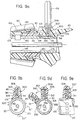
- an electrical contact arrangement 300 is utilized which ensures that power is not interrupted regardless of the rotational orientation of handle member 85.
- the electrical contact arrangement 300 comprises the electrode 99, a resilient metal spring element 305, and a metal contact element 311.
- the resilient metal spring element 305 is seated in a bore 310 in the handle member 85.
- the bore 310 is perpendicular to the longitudinal axis of the metal tube 20.
- Bore 310 includes a closed end 307 which forms the base 309 of electrode 99, and the resilient spring 305 bears against base 309. Because the resilient metal spring 305 is in compression, it is biased to urge the spherical metal contact 311, partially enclosed in bore 310, through a bore opening 316 and against the outer peripheral surface 313 of metal tube 20.
- metal element 311 will roll or slide along in contact with the outer periphery 313 of metal tube 20 such that continuous electrical contact between metal tube 20 and electrode 99 is maintained.
- a plurality of recesses, 330 are provided in a row 332 around the circumference 313 of metal tube 20.
- the recesses 330 preferably have a shape generally conforming to that of contact element 311 so that the contact element 311 securely seats in a recess 330 until handle 85 is rotated, e.g. as indicated at 340 in Figure 9d.
- handle 85 is rotated, contact element 311 moves up out of a recess 330 and over the peripheral outer surface 313 of metal tube 20 to another recess 330 until rotation is discontinued.
- the recesses 330 are preferably evenly spaced about the periphery of metal tube 20 so that a preselected angular rotation can be established by travel of element 311 over a particular number of recesses 330.
- the entire sleeve arrangement of the instrument can be simplified as it is the contact element 311 in conjunction with spring 305 which keeps the handle 85 from rotating relative to the tube 20.
- neither sleeve 90, inner sleeve or ferrule 90a, nor handle 84 includes the teeth and slot arrangement of Figure 9a. Also missing are the spring (103), the ring (124), etc.
- retaining ring 160 which prevents the handle (with the integral sleeve 90 and ferrule 90a which is fixed to sleeve 90) from sliding off of the tube 20, but which allows rotation of the handle 85 relative to the tube 20.
- a ferrule such as disclosed in copending application EP-A-0507622 can be utilized in conjunction with the step rotation mechanism of the electrode 99.
- protrusions and alternately shaped contact elements could be utilized.
- improved ratchet mechanisms for endoscopic tools are provided.
- the improved ratchet mechanism which can be used in conjunction with any medical tool and not just endoscopic tools enables end effectors 22, 24 to be locked in any of many positions (two such positions being shown in Fig. 10d) such that further movement of the end effectors toward each other is permitted, but further movement of the end effectors away from each other is not permitted except if the ratchet mechanism is purposely unlocked.
- Such a ratchet mechanism finds particular use in clamping devices, although it is not limited thereto.
- the ratchet mechanism comprises a cantilevered resilient strip 400 with a locking barb 412, where the strip 400 is located on one of the handle 85 and lever 75 of the surgical instrument, a ratchet element 499 located on the other of the handle 85 and lever 75 of the surgical instrument and having a plurality of teeth 419 radially displaced from a pivot 80 coupling the handle and lever, with each tooth 419 having an edge surface 498 on parallel axes which are parallel to the axis of the pivot 80, and a camming lever means 440 which in a first position forces the locking barb 412 into contact with the ratchet 499, and in a second position does not force the locking barb 412 into contact with the ratchet 499, wherein the barb 412 preferably also has an edge surface on an axis parallel to the axis of the pivot.
- the edge of the teeth 419 of the ratchet 499 are preferably located along an arc of a circle having its center point being the pivot
- the cantilevered resilient strip or leaf spring 400 (shown also in Figure 10c) has a downwardly extending punched out barb 401 for fixing the resilient strip 400 in the handle 85 of the surgical instrument, and an upwardly extending barb or locking element 412 for mating with the ratchet 499 in the lever member 75.
- Locking element 412 is preferably punched out of the resilient strip 400 and preferably makes a forty-five degree angle relative thereto.
- Locking element 412 preferably has an edge surface 497 which is parallel to the axis of pivot 80.
- the resilient strip 400 is inserted into a slot 402 in handle member 85 with the downwardly extending barb 401 extending into slot 403 of the handle member 85.
- the resilient strip 400 is engaged in the handle member 85 at a first location by a fixing post or surface 404 which establishes a cantilever engagement at the end portion 406 of strip 400; i.e. end portion 408 of resilient strip 400 is a "free" end.
- the fixing surface 404 is located substantially closer to barb 401 than to barb 412, and thereby provides a springy action.
- the springy action permits the teeth on the hereinafter described ratchet of the lever means to ride pass the barb in the direction of the barb such that further movement of the end effectors toward each other is permitted even after activation of the ratchet mechanism.
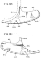
- the leaf spring 400 is maintained in the handle 85 via use of a handle cover 610 (shown in Figs. 10h and 10i) which includes several posts 612a, 614a which mate with post holes 612b and 614b on the handle 85 (seen in Fig. 10), and several mating surfaces 615a, 617a which mate with opposed surfaces or slots 615b, 617b on handle 85.
- a handle cover 610 shown in Figs. 10h and 10i
- the leaf spring 400 is maintained in the handle 85 via use of a handle cover 610 (shown in Figs. 10h and 10i) which includes several posts 612a, 614a which mate with post holes 612b and 614b on the handle 85 (seen in Fig. 10), and several mating surfaces 615a, 617a which mate with opposed surfaces or slots 615b, 617b on handle 85.
- the resilient strip 400 is preferably positioned at the portion 410 of handle member 85 which extends furthest and is most remote from the pivotal engagement 80 of lever arm 75 with handle member 85. Likewise, the resilient strip 400 extends at its free end portion 408 toward the portion 414 of the lever arm 75 which is most remote from pivotal engagement 80.
- the ratchet mechanism of the invention includes a ratchet 499 including teeth 419 and grooves 418 in the lever arm 75.
- an elongate arm 416 extends from lever arm 75 adjacent its remote portion 414.
- the elongate arm 416 includes the plurality of teeth 419 and grooves 418.
- a tandem array of teeth 419 are formed from the same material as the lever arm 75 in a recessed cutout fashion with the teeth traversing a portion of the width of elongate arm 416 (as seen in Fig. 10b), but with support edges 495 being kept intact.
- the width of the teeth 419 is just slightly wider than the width of the barb 412 to provide close lateral constraint for the locking barb 412.
- thirteen teeth are provided.
- the thirteen teeth traverse an arc of approximately seventeen degrees (i.e., one tooth every 1.3 degrees).
- the teeth are angled (as shown in Fig. 10-1 by angle "B") at forty-five degrees relative to the radius defined by pivot point 80, and the back edge of the teeth are provided with a ten degree re-entry angle (as shown in Fig. 10-1 by angle "C”) relative to the radius.
- the teeth edges 498 are formed so that they are located on an arc D which has a curving radius based on the distance between the edges 498 of the teeth 418 and the pivot pin 80; i.e., the edges of the teeth are located along an arc having the pivot pin as its center point.
- the teeth 419 With the teeth 419 at the provided angle B and preferably along the arc D, and with the barb 412 of the leaf spring 400 at a similar angle, when the barb 412 is mated into a groove 418 between the teeth 419 as hereinafter described, the teeth 419 can still ride pass the barb 412 in the direction of the barb such that further movement of the end effectors 22, 24 toward each other is obtained. However, movement in the opposite direction is not obtainable.
- the third element of the ratchet mechanism is the camming lever or latching means pivot arm 440.
- the camming lever has an integral post 442 intermediate its trigger end 450 and its cammed bearing end 451.
- the post 442 fits into post cutout holes 443a and 443b on the handle 85 and the handle cover 610 (seen in Fig. 10h and 10i) and thereby fixes the camming lever bearing end 451 adjacent the resilient strip 400 at a location adjacently forward the leaf spring fixing surface 404 towards the free end of resilient strip 400.
- Bearing end 451 of camming lever 440 has two distinct intersecting planar bearing faces 444 and 446.
- elongate arm 416 moves upon rotational movement of lever arm 75.
- the elongate arm 416 is arranged so that the ratchet comprised of the teeth 418 and groove 419 is brought into a closely adjacent opposed relationship with the resilient strip 400.
- the camming lever 440 may be advanced to the position 440F shown in Figure 1a and Figure 10 to lock the lever arm 75 relative to the handle 85 (and hence to lock the end effectors at a set position).
- the lever arm 75 and handle 85 may then be squeezed and moved closer together if desired, with the barb 412 riding over each tooth 419 and into another groove 418.
- Each locking position corresponds to a respective position of the end effector elements 22, 24 (two such positions being indicated in Figure 10d). However, unless the camming lever is returned to position 440, barb 412 will not disengage from the ratchet 499 in the transverse arm 416 to permit the end effectors to move away from each other.
- the transverse elongate arm 416' of lever member 75 is formed with an elongate open slot 800 extending along most of its length.
- the preformed slot 800 is formed with longitudinally spaced apart key ways 805, 807.
- a separately formed metal bar 850 is provided having a tandem array of integral toothlike elements 419' and grooves 418', and integral longitudinally spaced apart key elements 860, 861 on the side of metal bar 850 which is opposite to the toothlike members 419'.
- the metal bar 850 is inserted into slot 800 of elongate arm 416' to fit closely therein and securely engage elongate arm 416' by the forcible insertion of key elements 860, 861 into key ways 805, 807.
- the edges 498' of the toothlike members 419' of metal bar 850 are substantially coextensive with the outer edge 875 of elongate arm 416'.
- the metal bar 850 is preferably formed with the teeth edges located in an arc D which has a curving radius based on the distance between the edges 498 of the teeth 419' and the pivot pin 80; i.e., the edges 498' of the teeth 419' are located along an arc D having the pivot pin as its center point.
- Figure 1b and Figure 10 shows the preferred embodiment of the invention vis-a-vis the ratchet mechanism
- the resilient strip 400 can be engaged to the lever arm 75 instead of the handle member 85, and the elongate transverse arm 416 can be affixed to handle member 85 instead of elongate arm 416 (i.e., the parts are reversed).
- the elements of the preferred embodiment are located at the remote portions of lever arm 75 and handle member 85, they can be positioned instead at a location intermediate the pivotal engagement 80 and the remote extensions as indicated in phantom at 900 in Figure 1b.
- the arc D' on the ratchet teeth will have to be of proportionally diminished radius. Also, because movement in degrees along the arc defines movement of the end effectors, if fine adjustment is required, then proportionally much finer teeth and grooves (and hence a finer barb) are required in the intermediate location than the preferred location. Additionally, in order to accommodate the ratchet mechanism, either the handles must be much wider so that the ratchet teeth, leaf spring, camming lever, etc. can be inserted in the handle and the lever without compromising the structural integrity of the handle and lever, or the ratchet mechanism must be moved out of the plane of the handle and lever. If the ratchet mechanism is moved out of the plane of the handle and lever, care must be taken to still provide an arrangement where the pivot point 80 is still the center of the arc for the ratchet teeth.
Landscapes
- Health & Medical Sciences (AREA)
- Surgery (AREA)
- Life Sciences & Earth Sciences (AREA)
- Medical Informatics (AREA)
- Nuclear Medicine, Radiotherapy & Molecular Imaging (AREA)
- Engineering & Computer Science (AREA)
- Biomedical Technology (AREA)
- Heart & Thoracic Surgery (AREA)
- Ophthalmology & Optometry (AREA)
- Molecular Biology (AREA)
- Animal Behavior & Ethology (AREA)
- General Health & Medical Sciences (AREA)
- Public Health (AREA)
- Veterinary Medicine (AREA)
- Surgical Instruments (AREA)
- Endoscopes (AREA)
Claims (10)
- Instrument médical comprenant:(a) un tube extérieur creux (20) ayant une extrémité proximale, une extrémité distale et un axe longitudinal (185), ledit tube extérieur ayant une portion située de façon proximale présentant une pluralité d'irrégularités de surface (330) essentiellement identiques, espacées les unes des autres sur la périphérie;(b) une tige de poussoir (60) s'étendant à travers ledit tube extérieur (20) et ayant des extrémités proximales et distales;(c) des moyens de commande (50) pour transmettre un mouvement axial réciproque à ladite tige de poussoir par rapport audit tube extérieur, lesdits moyens de commande comprenant des moyens de blocage (85) s'accouplant de façon rotative avec ledit tube extérieur et un moyen de levier (75) s'accouplant de façon mobile avec ledit moyen de blocage et couplé autour de ladite extrémité proximale de ladite tige de poussoir;
lesdits moyens de blocage incluant un élément de contact (311) chargé à ressort, ayant une forme lui permettant de s'adapter auxdites irrégularités de surface (330), au niveau de ladite portion dudit tube extérieur située de façon proximale, selon une pluralité de premières positions de réglage de rotation, et de maintenir lesdits moyens de commande (50) fixés de façon rotative, par rapport audit tube extérieur (20), dans l'une desdites premières positions de réglage de rotation jusqu'à ce qu'une force de rotation suffisante soit transmise audit tube extérieur pour faire tourner ledit moyen de commande par rapport audit tube extérieur, en passant par une pluralité de secondes positions et vers une autre desdites premières positions de réglage;(d) des moyens effecteurs terminaux (22, 24) couplés à ladite tige de poussoir au niveau de ladite extrémité distale de ladite tige de poussoir (60) et couplés de façon pivotante audit tube extérieur, permettent de transformer ledit mouvement axial réciproque de ladite tige de poussoir en mouvement pivotant desdits moyens effecteurs terminaux;
caractérisé en ce que ledit moyen de blocage (85) est muni d'une électrode électriquement conductrice (99, 305, 311) ayant une première extrémité (99) s'étendant à travers ledit moyen de blocage, ledit élément de contact (311) étant électriquement conducteur et constituant la seconde extrémité de l'électrode. - Instrument médical selon la revendication 1, dans lequel lesdites irrégularités de surface (330) comprennent des indentations ou des évidements dans ledit tube extérieur (20), ledit élément de contact (311) ayant une forme lui permettant de s'adapter avec lesdites irrégularités de surface, et dans lequel ladite électrode inclut un ressort hélicoïdal (305).
- Instrument médical selon la revendication 2, dans lequel ledit moyen de blocage (85) comprend une poignée, dans lequel ladite poignée est couplée de façon pivotante audit moyen de levier (75), et ladite poignée (85) inclut une première portion creuse (120) entourant ladite première portion dudit tube extérieur (20) située de façon proximale, avec ladite première extrémité de ladite électrode (99) s'étendant à travers ladite poignée d'une façon perpendiculaire audit axe longitudinal, ladite poignée ayant de préférence un alésage perpendiculaire audit axe longitudinal pour recevoir de façon fixe ladite première extrémité de ladite électrode, et un évidement (310) partant dudit alésage pour recevoir ledit ressort hélicoïdal (305).
- Instrument médical selon l'une quelconque des revendications 1 à 3, dans lequel ledit élément de contact (311) est essentiellement de forme sphérique.
- Instrument médical selon la revendication 4, dans lequel ledit élément de blocage (85) comprend une poignée s'accouplant de façon pivotante avec ledit moyen de levier (75), et dans lequel ladite première extrémité de ladite électrode (99) est positionnée de façon fixe dans ladite poignée, avec ladite première extrémité de ladite électrode s'étendant vers l'extérieur depuis ladite poignée.
- Instrument médical selon l'une quelconque des revendications précédentes, dans lequel lesdites irrégularités (330) sont espacées radialement sur la surface radiale extérieure du tube (20), ladite électrode (99) étant prévue de façon perpendiculaire à l'axe longitudinal du tube.
- Instrument médical selon l'une quelconque des revendications précédentes, dans lequel ledit instrument médical comprend en outre des moyens (180) s'accouplant avec la tige de poussoir, ces moyens (180) s'accouplant avec la tige de poussoir comprenant un élément (190) dont la surface est au moins partiellement sphérique, ledit élément dont la surface est partiellement sphérique ayant un premier alésage (191) coaxial avec ladite tige de poussoir (60) et recevant celle-ci, dans lequel ledit moyen de levier (75) possède un second alésage (200) qui reçoit de façon serrée, coulissante et rotative ledit élément dont la surface est partiellement sphérique, dans lequel la rotation dudit moyen de levier (75) par rapport audit tube extérieur (20) provoque la rotation dudit moyen de levier (75) par rapport auxdits moyens (180) s'accouplant avec la tige de poussoir.
- Instrument médical selon la revendication 7, dans lequel ledit second alésage (200) s'étend au moins partiellement à travers ledit moyen de levier (75) et est en sens transversal audit axe longitudinal (185), ledit moyen de levier possédant un troisième alésage (210) prévu en sens transversal audit second alésage, et recevant ladite tige de poussoir et de façon à permettre le libre mouvement de ladite tige de poussoir durant le mouvement de pivotement dudit moyen de levier, par rapport auxdits moyens de blocage, et dans lequel ledit élément (190) dont la surface est partiellement sphérique est une sphère essentiellement complète ayant un alésage recevant une vis sans tête (192), perpendiculaire audit premier alésage, et dans lequel ledit instrument médical comprend en outre une vis sans tête (192) s'étendant dans ledit alésage recevant la vis sans tête et orientant ledit élément (190) recevant la tige de poussoir par rapport à ladite tige de poussoir, et dans lequel ladite vis sans tête est essentiellement contenue dans ledit alésage recevant la vis sans tête.
- Instrument médical selon la revendication 7 ou la revendication 8, dans lequel ledit élément (190) dont la surface est au moins partiellement sphérique est une sphère essentiellement complète, présentant un premier rayon avec une portion de cercle de forme cylindrique présentant un second rayon plus petit que ledit premier rayon, ladite portion de cercle étant essentiellement coaxiale avec ledit premier alésage, dans lequel ledit second alésage possède un troisième rayon plus petit que ledit premier rayon et au moins aussi grand que ledit second rayon.
- Instrument médical selon la revendication 9, dans lequel ladite sphère essentiellement complète (190) ayant une portion de cercle de forme cylindrique possède un alésage recevant une vis sans tête (192), perpendiculaire audit premier alésage et s'étendant depuis à travers ladite portion de cercle de forme cylindrique vers ledit premier alésage, et ledit instrument médical comprend en outre une vis sans tête (192) s'étendant dans ledit alésage recevant la vis sans tête et orientant ledit élément (190) recevant la tige de poussoir par rapport à ladite tige de poussoir (60), dans lequel ladite vis sans tête (192) est essentiellement contenue dans ledit alésage recevant la vis sans tête.
Applications Claiming Priority (2)
| Application Number | Priority Date | Filing Date | Title |
|---|---|---|---|
| US83384292A | 1992-02-07 | 1992-02-07 | |
| US833842 | 1992-02-07 |
Publications (2)
| Publication Number | Publication Date |
|---|---|
| EP0555105A1 EP0555105A1 (fr) | 1993-08-11 |
| EP0555105B1 true EP0555105B1 (fr) | 1997-08-06 |
Family
ID=25265415
Family Applications (1)
| Application Number | Title | Priority Date | Filing Date |
|---|---|---|---|
| EP93300906A Expired - Lifetime EP0555105B1 (fr) | 1992-02-07 | 1993-02-05 | Instrument de chirurgie endoscopique ayant des effecteurs terminaux pivotables |
Country Status (8)
| Country | Link |
|---|---|
| EP (1) | EP0555105B1 (fr) |
| JP (1) | JP2573783B2 (fr) |
| AT (1) | ATE156342T1 (fr) |
| AU (2) | AU3656993A (fr) |
| CA (1) | CA2088868A1 (fr) |
| DE (1) | DE69312754T2 (fr) |
| IL (1) | IL104593A0 (fr) |
| WO (1) | WO1993015663A1 (fr) |
Families Citing this family (16)
| Publication number | Priority date | Publication date | Assignee | Title |
|---|---|---|---|---|
| US5472439A (en) * | 1993-10-06 | 1995-12-05 | American Cyanamid Company | Endoscopic surgical instrument with rotatable inner shaft |
| AU1176195A (en) * | 1993-11-09 | 1995-05-29 | Innovative Surgical, Inc. | Minimally-invasive surgical instrument and modified ratchet |
| US5562655A (en) * | 1994-08-12 | 1996-10-08 | United States Surgical Corporation | Surgical apparatus having a universal handle for actuating various attachments |
| US5609601A (en) * | 1994-09-23 | 1997-03-11 | United States Surgical Corporation | Endoscopic surgical apparatus with rotation lock |
| DE4442439C2 (de) * | 1994-11-29 | 1997-09-04 | Aesculap Ag | Chirurgisches Rohrschaftinstrument |
| US5713505A (en) * | 1996-05-13 | 1998-02-03 | Ethicon Endo-Surgery, Inc. | Articulation transmission mechanism for surgical instruments |
| US5823066A (en) * | 1996-05-13 | 1998-10-20 | Ethicon Endo-Surgery, Inc. | Articulation transmission mechanism for surgical instruments |
| DE19852682C2 (de) | 1998-11-16 | 2000-11-16 | Robert Mueller | Chirurgisches Schienenschaftinstrument |
| NO322695B1 (no) * | 2004-12-29 | 2006-11-27 | Surgitech Norway As | Instrument, saerlig til bruk ved laparoskopisk kirurgisk inngrep |
| US7846177B2 (en) | 2006-06-26 | 2010-12-07 | Carefusion 2200, Inc. | Surgical device |
| GB2460392B (en) * | 2008-02-29 | 2012-08-01 | Surgical Innovations Ltd | Handle |
| US8197501B2 (en) | 2008-03-20 | 2012-06-12 | Medtronic Xomed, Inc. | Control for a powered surgical instrument |
| GB2466180B (en) * | 2008-12-05 | 2013-07-10 | Surgical Innovations Ltd | Surgical instrument, handle for a surgical instrument and surgical instrument system |
| US10918393B2 (en) * | 2017-11-05 | 2021-02-16 | Grena Usa Llc | Surgical appliance |
| AU2019271230B2 (en) * | 2018-05-17 | 2025-01-30 | Smith & Nephew Asia Pacific Pte Limited | Tissue repair device and method |
| RU206775U1 (ru) * | 2020-12-15 | 2021-09-28 | Федеральное государственное бюджетное образовательное учреждение высшего образования "Саратовский государственный технический университет имени Гагарина Ю.А." (СГТУ имени Гагарина Ю.А.) | Электрод для электрокоагуляции биологических тканей |
Family Cites Families (6)
| Publication number | Priority date | Publication date | Assignee | Title |
|---|---|---|---|---|
| US3506012A (en) * | 1967-08-01 | 1970-04-14 | Ivan E Brown | Polyp clamp and applier therefor |
| US5066295A (en) * | 1986-05-13 | 1991-11-19 | Mill-Rose Laboratories, Inc. | Rotatable surgical snare |
| US4760848A (en) * | 1986-11-03 | 1988-08-02 | Hasson Harrith M | Rotational surgical instrument |
| US4950273A (en) * | 1987-10-26 | 1990-08-21 | Briggs Jeffrey M | Cable action instrument |
| US5035696A (en) * | 1990-02-02 | 1991-07-30 | Everest Medical Corporation | Electrosurgical instrument for conducting endoscopic retrograde sphincterotomy |
| DE9007356U1 (de) * | 1990-05-18 | 1991-05-16 | Olympus Winter & Ibe Gmbh, 22045 Hamburg | Medizinisch endoskopisches Greif- bzw. Schneidwerkzeug |
-
1993
- 1993-02-02 AU AU36569/93A patent/AU3656993A/en not_active Abandoned
- 1993-02-02 WO PCT/US1993/000910 patent/WO1993015663A1/fr not_active Ceased
- 1993-02-03 IL IL93104593A patent/IL104593A0/xx unknown
- 1993-02-05 AT AT93300906T patent/ATE156342T1/de not_active IP Right Cessation
- 1993-02-05 EP EP93300906A patent/EP0555105B1/fr not_active Expired - Lifetime
- 1993-02-05 AU AU32833/93A patent/AU655530B2/en not_active Ceased
- 1993-02-05 CA CA002088868A patent/CA2088868A1/fr not_active Abandoned
- 1993-02-05 JP JP5019082A patent/JP2573783B2/ja not_active Expired - Lifetime
- 1993-02-05 DE DE69312754T patent/DE69312754T2/de not_active Expired - Fee Related
Also Published As
| Publication number | Publication date |
|---|---|
| DE69312754D1 (de) | 1997-09-11 |
| DE69312754T2 (de) | 1998-03-12 |
| AU3283393A (en) | 1993-08-12 |
| AU3656993A (en) | 1993-09-03 |
| AU655530B2 (en) | 1994-12-22 |
| JP2573783B2 (ja) | 1997-01-22 |
| EP0555105A1 (fr) | 1993-08-11 |
| WO1993015663A1 (fr) | 1993-08-19 |
| ATE156342T1 (de) | 1997-08-15 |
| IL104593A0 (en) | 1993-06-10 |
| CA2088868A1 (fr) | 1993-08-07 |
| JPH0614876A (ja) | 1994-01-25 |
Similar Documents
| Publication | Publication Date | Title |
|---|---|---|
| EP0555104B1 (fr) | Instrument de chirurgie endoscopique ayant des effecteurs terminaux pivotables | |
| US5293878A (en) | Endoscopic surgical instruments having stepped rotatable end effectors | |
| US5176702A (en) | Ratchet locking mechanism for surgical instruments | |
| EP0555105B1 (fr) | Instrument de chirurgie endoscopique ayant des effecteurs terminaux pivotables | |
| US10537381B2 (en) | Surgical instrument having a bipolar end effector assembly and a deployable monopolar assembly | |
| US5133735A (en) | Thumb-activated actuating member for imparting reciprocal motion to push rod of a disposable laparoscopic surgical instrument | |
| KR101561366B1 (ko) | 안정화 가능한 관절 액추에이터를 갖는 관절운동 가능한 전기수술 기구 | |
| US5171256A (en) | Single acting disposable laparoscopic scissors | |
| US11911015B2 (en) | Methods and devices for auto return of articulated end effectors | |
| US5618304A (en) | Surgical instrument | |
| US5342390A (en) | Thumb-activated actuating member for imparting reciprocal motion to a push rod of a disposable laparoscopic surgical instrument | |
| EP2227149A1 (fr) | Instrument chirurgical | |
| WO1992017120A2 (fr) | Virole d'isolation d'instrument chirurgical endoscopique | |
| EP3383286B1 (fr) | Dispositifs pour augmenter le couple de rotation pendant l'articulation d'un effecteur d'extrémité | |
| IL101494A (en) | Thumb activated actuating member for imparting reciprocal motion to push rod of an endoscopic surgical instrument |
Legal Events
| Date | Code | Title | Description |
|---|---|---|---|
| PUAI | Public reference made under article 153(3) epc to a published international application that has entered the european phase |
Free format text: ORIGINAL CODE: 0009012 |
|
| AK | Designated contracting states |
Kind code of ref document: A1 Designated state(s): AT BE CH DE DK ES FR GB GR IE IT LI LU MC NL PT SE |
|
| 17P | Request for examination filed |
Effective date: 19940126 |
|
| 17Q | First examination report despatched |
Effective date: 19951108 |
|
| GRAG | Despatch of communication of intention to grant |
Free format text: ORIGINAL CODE: EPIDOS AGRA |
|
| GRAH | Despatch of communication of intention to grant a patent |
Free format text: ORIGINAL CODE: EPIDOS IGRA |
|
| GRAH | Despatch of communication of intention to grant a patent |
Free format text: ORIGINAL CODE: EPIDOS IGRA |
|
| GRAA | (expected) grant |
Free format text: ORIGINAL CODE: 0009210 |
|
| AK | Designated contracting states |
Kind code of ref document: B1 Designated state(s): AT BE CH DE DK ES FR GB GR IE IT LI LU MC NL PT SE |
|
| PG25 | Lapsed in a contracting state [announced via postgrant information from national office to epo] |
Ref country code: NL Free format text: LAPSE BECAUSE OF FAILURE TO SUBMIT A TRANSLATION OF THE DESCRIPTION OR TO PAY THE FEE WITHIN THE PRESCRIBED TIME-LIMIT Effective date: 19970806 Ref country code: LI Effective date: 19970806 Ref country code: IT Free format text: LAPSE BECAUSE OF FAILURE TO SUBMIT A TRANSLATION OF THE DESCRIPTION OR TO PAY THE FEE WITHIN THE PRESCRIBED TIME-LIMIT;WARNING: LAPSES OF ITALIAN PATENTS WITH EFFECTIVE DATE BEFORE 2007 MAY HAVE OCCURRED AT ANY TIME BEFORE 2007. THE CORRECT EFFECTIVE DATE MAY BE DIFFERENT FROM THE ONE RECORDED. Effective date: 19970806 Ref country code: GR Free format text: LAPSE BECAUSE OF FAILURE TO SUBMIT A TRANSLATION OF THE DESCRIPTION OR TO PAY THE FEE WITHIN THE PRESCRIBED TIME-LIMIT Effective date: 19970806 Ref country code: ES Free format text: THE PATENT HAS BEEN ANNULLED BY A DECISION OF A NATIONAL AUTHORITY Effective date: 19970806 Ref country code: DK Free format text: LAPSE BECAUSE OF NON-PAYMENT OF DUE FEES Effective date: 19970806 Ref country code: CH Effective date: 19970806 Ref country code: BE Effective date: 19970806 Ref country code: AT Effective date: 19970806 |
|
| REF | Corresponds to: |
Ref document number: 156342 Country of ref document: AT Date of ref document: 19970815 Kind code of ref document: T |
|
| REG | Reference to a national code |
Ref country code: CH Ref legal event code: EP |
|
| REF | Corresponds to: |
Ref document number: 69312754 Country of ref document: DE Date of ref document: 19970911 |
|
| PG25 | Lapsed in a contracting state [announced via postgrant information from national office to epo] |
Ref country code: SE Effective date: 19971106 |
|
| PG25 | Lapsed in a contracting state [announced via postgrant information from national office to epo] |
Ref country code: PT Effective date: 19971111 |
|
| ET | Fr: translation filed | ||
| NLV1 | Nl: lapsed or annulled due to failure to fulfill the requirements of art. 29p and 29m of the patents act | ||
| PG25 | Lapsed in a contracting state [announced via postgrant information from national office to epo] |
Ref country code: LU Free format text: LAPSE BECAUSE OF NON-PAYMENT OF DUE FEES Effective date: 19980205 |
|
| REG | Reference to a national code |
Ref country code: CH Ref legal event code: PL |
|
| PLBE | No opposition filed within time limit |
Free format text: ORIGINAL CODE: 0009261 |
|
| STAA | Information on the status of an ep patent application or granted ep patent |
Free format text: STATUS: NO OPPOSITION FILED WITHIN TIME LIMIT |
|
| 26N | No opposition filed | ||
| PG25 | Lapsed in a contracting state [announced via postgrant information from national office to epo] |
Ref country code: MC Free format text: LAPSE BECAUSE OF NON-PAYMENT OF DUE FEES Effective date: 19980831 |
|
| REG | Reference to a national code |
Ref country code: GB Ref legal event code: IF02 |
|
| PGFP | Annual fee paid to national office [announced via postgrant information from national office to epo] |
Ref country code: GB Payment date: 20020108 Year of fee payment: 10 |
|
| PGFP | Annual fee paid to national office [announced via postgrant information from national office to epo] |
Ref country code: IE Payment date: 20020122 Year of fee payment: 10 |
|
| PGFP | Annual fee paid to national office [announced via postgrant information from national office to epo] |
Ref country code: FR Payment date: 20020131 Year of fee payment: 10 |
|
| PGFP | Annual fee paid to national office [announced via postgrant information from national office to epo] |
Ref country code: DE Payment date: 20020228 Year of fee payment: 10 |
|
| PG25 | Lapsed in a contracting state [announced via postgrant information from national office to epo] |
Ref country code: IE Free format text: LAPSE BECAUSE OF NON-PAYMENT OF DUE FEES Effective date: 20030205 Ref country code: GB Free format text: LAPSE BECAUSE OF NON-PAYMENT OF DUE FEES Effective date: 20030205 |
|
| PG25 | Lapsed in a contracting state [announced via postgrant information from national office to epo] |
Ref country code: DE Free format text: LAPSE BECAUSE OF NON-PAYMENT OF DUE FEES Effective date: 20030902 |
|
| GBPC | Gb: european patent ceased through non-payment of renewal fee | ||
| PG25 | Lapsed in a contracting state [announced via postgrant information from national office to epo] |
Ref country code: FR Free format text: LAPSE BECAUSE OF NON-PAYMENT OF DUE FEES Effective date: 20031031 |
|
| REG | Reference to a national code |
Ref country code: FR Ref legal event code: ST |
|
| REG | Reference to a national code |
Ref country code: IE Ref legal event code: MM4A |