EP0555156B1 - Automatikgurt für Handwerkzeuge, insbesondere Eispickel - Google Patents
Automatikgurt für Handwerkzeuge, insbesondere Eispickel Download PDFInfo
- Publication number
- EP0555156B1 EP0555156B1 EP19930420017 EP93420017A EP0555156B1 EP 0555156 B1 EP0555156 B1 EP 0555156B1 EP 19930420017 EP19930420017 EP 19930420017 EP 93420017 A EP93420017 A EP 93420017A EP 0555156 B1 EP0555156 B1 EP 0555156B1
- Authority
- EP
- European Patent Office
- Prior art keywords
- strap
- section
- tool
- handle
- loop
- Prior art date
- Legal status (The legal status is an assumption and is not a legal conclusion. Google has not performed a legal analysis and makes no representation as to the accuracy of the status listed.)
- Expired - Lifetime
Links
- 210000000707 wrist Anatomy 0.000 claims description 36
- 238000006073 displacement reaction Methods 0.000 claims description 3
- 239000004744 fabric Substances 0.000 claims description 3
- 230000002787 reinforcement Effects 0.000 claims description 2
- 230000014759 maintenance of location Effects 0.000 claims 1
- XEEYBQQBJWHFJM-UHFFFAOYSA-N Iron Chemical compound [Fe] XEEYBQQBJWHFJM-UHFFFAOYSA-N 0.000 description 2
- 238000000034 method Methods 0.000 description 2
- 230000000717 retained effect Effects 0.000 description 2
- 230000006978 adaptation Effects 0.000 description 1
- 238000013459 approach Methods 0.000 description 1
- 239000008280 blood Substances 0.000 description 1
- 210000004369 blood Anatomy 0.000 description 1
- 230000000694 effects Effects 0.000 description 1
- 239000011521 glass Substances 0.000 description 1
- 229910052742 iron Inorganic materials 0.000 description 1
- 238000012423 maintenance Methods 0.000 description 1
- 239000000463 material Substances 0.000 description 1
- 238000011144 upstream manufacturing Methods 0.000 description 1
Images
Classifications
-
- A—HUMAN NECESSITIES
- A63—SPORTS; GAMES; AMUSEMENTS
- A63B—APPARATUS FOR PHYSICAL TRAINING, GYMNASTICS, SWIMMING, CLIMBING, OR FENCING; BALL GAMES; TRAINING EQUIPMENT
- A63B29/00—Apparatus for mountaineering
- A63B29/08—Hand equipment for climbers
Definitions
- the present invention relates to traction straps adaptable to a hand tool such as an ice ax provided with a handle, one free end of which forms a gripping zone and the opposite end of which is connected to a tool head.
- the strap is provided with means for hooking to the handle in the vicinity of the tool head.
- the strap forms a loop in the vicinity of the gripping area to allow the passage and maintenance of the wrist with one hand of the user holding the tool by said gripping area.
- the ice ax comprises a tool head provided with a blade extending in a generally transverse direction relative to the axis of the handle.
- the user by a striking movement, plants the tool head blade in the wall of ice he wants to climb, the handle developing downstream.
- the user can then pull on the handle to move upstream. He then releases the tool head blade from the glass wall, and replants it higher to start the traction movement again.
- the traction can naturally be supported by the hand, surrounding the grip part of the handle.
- straps have been provided in certain known ice axes, as in other mountaineering tools as described in document FR-A-2 134 953, to surround the wrist with the hand passed around the handle, the strap being likely to support all or part of the tool holding effort, to relieve the hand.
- the strap forms a loop surrounding the wrist, this loop having to be tightened when the wrist is in the traction position with the hand passed around the grip part of the handle.
- the user must therefore adapt the length of the strap loop to the circumference dimension of the wrist.
- a first maneuver is necessary to adjust this length and put the strap in the pulling position.
- a second maneuver is necessary when the user wants to completely release his hand from the strap.
- traditional means for adjusting the strap length are provided for this, the operation of which requires the intervention of the other hand of the user or his teeth.
- the problem proposed by the present invention is to design a new traction strap structure for a hand tool such as an ice ax in which the adaptation and tightening of the strap around the wrist in the traction position can be done by movement of the only hand whose wrist and passed through the strap, and in which the complete release of the hand out of the blood can also be done by moving the only hand whose wrist and passed through the strap, without ever require the intervention of the other hand of the user or his teeth. Simultaneously, in the pulling position, the strap, passing around the wrist, must not have a noose effect tending to tighten the wrist excessively. The strap should just tighten the wrist so that it cannot come out, and thus avoid the loss of the tool.
- the strap should be adjustable to accommodate common ice ax lengths.
- the strap length is adjustable, to adapt to the length of the tool handle portion located between the tool head and the gripping area.
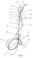
- the hand tool receiving a strap is a technical ice ax provided with a handle 1 with a grip zone 2 in the vicinity of its free end 3.
- the end opposite 4 of the handle is connected to a tool head 5 by a junction zone 6.
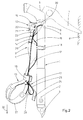
- the tool head 5 comprises in particular a blade 7 intended to be planted in an ice wall 8, the handle 1 then developing towards the 'downstream as shown in Figure 2.
- the strap 9 is provided, at a first end, with hooking means 10 for its attachment to the tool head 5. At its second end, the strap 9 forms a holding loop 13 shaped to surround the wrist of a user.
- the strap 9 is formed of a first strand 11 and a second strand 12 generally parallel to one another.
- the first ends 14 and 15 of the two strands are secured by the hooking means 10.
- these first ends of strands 11 and 12 are secured by a transverse seam 33.
- the second opposite ends of the two strands 11 and 12 are integral with one another in continuity to form the retaining loop 13, as shown in the figures.
- the two strands 11 and 12 pass simultaneously in the same pass 16.
- the first strand 11 slides freely in the pass 16.
- the pass 16 is secured to the second strand 12 by fastening means 17, at the base of the loop. holding 13.
- the holding loop 13 is formed by the strap part connecting the two strands 11 and 12 and leaving the passer-by 16 opposite the attachment means 10.
- the second strand 12 further cooperates with a holding means 18, in an intermediate zone of the second strand 12 between its first end 15 and the loop 16.
- the holding means 18 is shaped to be fixed in a chosen intermediate zone of the handle 1 of tool, and to thus secure said intermediate zone of second strand 12 to said chosen intermediate zone of handle 1 of tool.
- the retaining loop 13 is of adjustable length by sliding the first strand 11 of strap in the pass 16. The sliding is obtained automatically on opening and closing by simple movement of the user's wrist passed through the holding loop 13.
- the attachment means 10 comprise length adjustment means, making it possible to adapt the length of the strap 9 to the length of the tool handle 1, in order to position the holding loop 13 at the level of the gripping area 2 of the tool handle 1.
- the hooking means 10 comprise a strap extension 19, extending the second strand 12 beyond its first end 15.
- the extension 19 is intended to pass through a lumen 20 provided in the tool head 5.
- Two rings 21 and 22 are fixed to the first end 14 of the first strap strand 11 by a strap loop 23. After passing through the opening 20, the extension 19 can be wedged in known manner in the two rings 21 and 22, to ensure the attachment of the strap 9 to the tool head 5 and its length adjustment.
- the fastening means 17 of the loop 16 comprises a pull tab 24 secured to the loop 16 and provided with a hooking face cooperating with a corresponding face of the second strand 12 of strap.
- the two hooking faces constitute a removable hooking zone 25 of the hook-fabric-loop fabric type. It is thus possible, by displacement of the pull tab 24 on the second strand 12, the circumference of the holding loop 13 to adapt it to the circumference of the wrist of the user.
- the holding means 18 may advantageously be a holding tongue secured transversely to the second strand 12, and shaped to surround and tighten the tool handle 1.
- the two ends of the retaining tab are shaped to hang one on the other in a removable manner, by providing, for example, faces of the hook-fabric-loop fabric type.
- the holding means 18 may include a hole in the appropriate intermediate part of the tool handle 1, hole through which the second strap strand 12 passes.
- the connection function between the second strand intermediate zone 12 and the intermediate handle region 1 of the tool is thus provided in an equivalent manner.
- the first strand 11 advantageously comprises, in the vicinity of its first end 14, an extra thickness 26 constituting a brake to oppose the sliding of the first strand 11 in the loop 16 when the strap is in the open position.
- the additional thickness may simply consist of the strap return after the loop 23, secured to the first strand 11 by seams.
- the holding loop 13 can advantageously be provided with a secondary self-insurance loop 28, as shown in the figures.
- the self-insurance loop 28 is shaped to allow the passage of a carabiner.
- the holding loop 13 is advantageously provided with a reinforcement 27, increasing the bearing surface of the strap in this holding zone, to increase the comfort of the user.
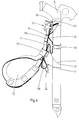
- the operation of the strap 9 according to the invention is as follows: the strap is shown in FIG. 4 in the open position, position in which the holding loop 13 has a circumference which substantially exceeds the circumference of a user's wrist. In this position, the user can therefore easily pass his hand through the holding loop 13.
- the tightening of the holding loop is then limited.
- the strap is then in the pulling position, its two strands 11 and 12 being stretched between the hooking means 10 and the holding loop 13, the holding loop 13 being fitted tightly around the wrist of the user whose hand is holding simultaneously the gripping zone 2 of the tool, the circumference of the holding loop 13 being determined by the chosen position of the pull tab 24 for fastening the loop 16 to the second strand 12.
- the user can simply exert a pulling movement of the wrist engaged in the holding loop 13, the pulling being carried out away from the handle 1 in a direction not parallel to the handle 1 and not directed opposite the tool head 5.
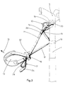
- traction can be effected by rotational movement illustrated in FIG. 3 according to arrow 31.
- the passer-by 16 is retained by the second strand 12, at constant distance from the retaining tongue 18, while the entire retaining loop approaches the hooking means 10.
- the first strand 11 is then relaxed, so that a pull of the wrist on the holding loop 13 causes the first strand 11 to slide in the loop 16 as shown by arrow 32, which increases the circumference of the holding loop 13 and allows the hand to be released from the holding loop 13.
- the user can interrupt the movement in the intermediate position, the strap then remaining in the open position shown in FIG. 4.
- the first strand 11 slides in the loop 16, and can advantageously slide to a fully open position in which the loop reaches the region of the first end of the first strand 11, zone occupied by the extra thickness 26. If the user releases the strap 9 in this fully open position, the passer-by 16 is braked by the extra thickness 26, so that the retaining loop 13 remains more securely in the open position, in which its diameter is much greater than that of the user's wrist.
- the user can very easily iron his hand in the holding loop 13, which has retained a circumference much greater than that of the wrist.
- the strands 11 and 12 can be produced by a cord, a strap, a cable or any other form of link.
- the retaining loop 13 can advantageously be made of a material and in a form suitable for receiving the wrist and forming a sufficient bearing surface.
- the retaining loop 13 may have a form of strap of greater width, increasing the comfort of the user.
Landscapes
- Health & Medical Sciences (AREA)
- Pulmonology (AREA)
- General Health & Medical Sciences (AREA)
- Physical Education & Sports Medicine (AREA)
- Purses, Travelling Bags, Baskets, Or Suitcases (AREA)
Claims (11)
- Zuggurt, der an ein Handwerkzeug, wie einen Eispickel, anpaßbar ist, welches mit einem Griff (1) mit einer Greifzone (2) in der Nähe eines freien Endes (3) versehen ist, wobei sich das entgegengesetzte Ende (4) des Griffes (1) mit einem Werkzeugkopf (5) über eine Verbindungszone (6) verbindet, der Gurt (9) mit Mitteln (10) zum Anhängen an den Werkzeugkopf (5) versehen ist, und der Gurt (9) in der Nähe der Greifzone (2) eine Halteschlaufe (13) für das Hindurchführen und das Halten eines Handgelenks des Benutzers bildet, um die besagte Greifzone zu halten, dadurch gekennzeichnet, daß:- der Gurt zwischen den Anhängemitteln (10) und der Halteschlaufe (13) mit einer ersten (11) und mit einer zweiten (12) Teillänge gebildet ist, die generell parallel zueinander verlaufen,- die ersten Enden (14, 15) der beiden Teillängen durch die Anhängemittel (10) verbunden sind,- die entgegengesetzten zweiten Enden der beiden Teillängen miteinander fortlaufend verbunden sind, um die Halteschlaufe (13) zu bilden,- die beiden Teillängen gleichzeitig durch eine und dieselbe Schlaufe (16) hindurchgehen, wobei die erste Teillänge (11) in der besagten Schlaufe (16) frei verschiebbar ist,- die Schlaufe (16) mit der zweiten Teillänge (12) durch Verbindungsmittel (17) mit der Basis der Halteschlaufe (13) verbunden ist,- ein Haltemittel (18) die Verbindung zwischen einer mittleren Zone der zweiten Teillänge (12) und einer ausgewählten mittleren Zone des Griffs (1) des Werkzeuges sichert,- derart, daß die Halteschlaufe (13) durch ein Verschieben der ersten Teillänge (11) des Gurtes in der Schlaufe (16) eine regelbare Länge aufweist, wobei die Verschiebung durch eine einfache Verlagerung des in der Halteschlaufe (13) hindurchgeführten Handgelenks des Benutzers bei der Öffnung und bei der Schließung automatisch erhalten wird.
- Gurt nach Anspruch 1, dadurch gekennzeichnet, daß die beiden zwischen den Anhängemitteln (10) und der Halteschlaufe (13) verlaufenden Teillängen (11, 12) eine solche Länge haben, daß die Halteschlaufe (13) in der Ebene der Greifzone (2) des Griffs (1) des Werkzeuges angeordnet ist.
- Gurt nach einem der Ansprüche 1 oder 2, dadurch gekennzeichnet, daß die Anhängemittel (10) Mittel zum Regeln der Länge aufweisen, um die Gurtlänge an die Länge des Griffs (1) des Werkzeuges anzupassen und um die Halteschlaufe (13) in der Ebene der Greifzone (2) des Griffes (1) des Werkzeuges zu positionieren.
- Gurt nach Anspruch 3, dadurch gekennzeichnet, daß die Anhängemittel (10) bestehen aus:- einer Verlängerung (19) des Gurtes, welche die zweite Teillänge (12) über ihr erstes Ende (15) hinaus verlängert und dazu bestimmt ist, ein in dem Werkzeugkopf (5) vorgesehenes Loch (20) zu durchqueren,- zwei Ringen (21, 22), die an dem ersten Ende (14) der ersten Teillänge (11) durch eine Gurtschlaufe (23) befestigt sind und in welchen sich das Ende der Verlängerung (19) des Gurtes verklemmen kann, um das Anhängen des Gurtes an den Werkzeugkopf (5) und seine Längenregelung zu sichern.
- Gurt nach einem der Ansprüche 1 bis 4, dadurch gekennzeichnet, daß das Verbindungsmittel (17) der Schlaufe (16) eine Zuglasche (24) aufweist, die mit der Schlaufe verbunden und mit einer Anhängefläche versehen ist, die mit einer entsprechenden Fläche der zweiten Teillänge (12) zusammenwirkt, um eine lösbare Anhängezone (25) des Typs eines Gewebeklettverschlusses zu bilden.
- Gurt nach einem der Ansprüche 1 bis 5, dadurch gekennzeichnet, daß das Haltemittel (18) eine Haltezunge ist, die an der zweiten Teillänge (12) quer verlaufend befestigt und dafür vorgesehen ist, den Griff (1) des Werkzeuges zu umgeben und einzuspannen und um sich in einer zu sich selbst mit ihren beiden Enden lösbaren Art und Weise anzuhängen.
- Gurt nach einem der Ansprüche 1 bis 6, dadurch gekennzeichnet, daß die erste Teillänge (11) in der Nähe ihres ersten Endes (14) eine Überdicke (26) aufweist, die eine Bremse bildet, welche der Verschiebung der ersten Teillänge in der Schlaufe (16) entgegenwirkt, um den Gurt in der geöffneten Position zu halten.
- Gurt nach einem der Ansprüche 1 bis 7, dadurch gekennzeichnet, daß die Halteschlaufe (13) mit einer zweiten selbstsichernden Schlaufe (28) versehen ist.
- Gurt nach einem der Ansprüche 1 bis 8, dadurch gekennzeichnet, daß die Halteschlaufe (13) mit einer Verstärkung (27) versehen ist, welche die Tragefläche des Gurts vergrößert.
- Handwerkzeug, wie ein Eispickel, dadurch gekennzeichnet, daß es einen Zuggurt (9) gemäß einem der Ansprüche 1 bis 9 aufweist.
- Handwerkzeug mit einem Zuggurt (9), wie ein Eispickel, das mit einem Griff (1) mit einer Greifzone (2) in der Nähe eines freien Endes (3) versehen ist, wobei sich das entgegengesetzte Ende (4) des Griffes (1) mit einem Werkzeugkopf (5) verbindet, wobei der Zuggurt (9) eine erste Gurtteillänge (11) und eine zweite Gurtteillänge (12) aufweist, die generell parallel zueinander verlaufen und an ihren zweiten Enden zueinander fortlaufend verbunden sind, um eine Halteschlaufe (13) zu bilden, mit Anhängemitteln (10) die eine Verlängerung (19) aufweisen, welche die zweite Gurtteillänge (12) über ihr erstes Ende (15) hinaus verlängert und ein Loch (20) durchquert, das in der Zone des Werkzeugkopfes (5) vorgesehen ist, um sich an das erste Ende (14) der ersten Gurtteillänge (11) anzuhängen, wobei bei diesem Werkzeug:- eine Schlaufe (16) an der zweiten Gurtteillänge (12) durch Befestigungsmittel (17) an der Basis der Halteschlaufe (13) befestigt ist,- die erste Gurtteillänge (11) sich in der Schlaufe (16) frei verschiebt,- die zweite Gurtteillänge (12) ein Loch durchquert, das in einer geeigneten mittleren Zone des Griffes (1) angebracht ist,derart, daß die Halteschlaufe (13) durch ein Verschieben der ersten Gurtteillänge (11) in der Schlaufe (16) eine regelbare Länge aufweist, wobei die Verschiebung durch eine einfache Verlagerung des in der Halteschlaufe (13) hindurchgeführten Handgelenks des Benutzers bei der Öffnung und bei der Schließung automatisch erhalten wird.
Applications Claiming Priority (2)
| Application Number | Priority Date | Filing Date | Title |
|---|---|---|---|
| FR9200904 | 1992-01-23 | ||
| FR9200904A FR2686518B1 (fr) | 1992-01-23 | 1992-01-23 | Sangle automatique pour outils a main tels que piolets. |
Publications (2)
| Publication Number | Publication Date |
|---|---|
| EP0555156A1 EP0555156A1 (de) | 1993-08-11 |
| EP0555156B1 true EP0555156B1 (de) | 1995-03-08 |
Family
ID=9426060
Family Applications (1)
| Application Number | Title | Priority Date | Filing Date |
|---|---|---|---|
| EP19930420017 Expired - Lifetime EP0555156B1 (de) | 1992-01-23 | 1993-01-18 | Automatikgurt für Handwerkzeuge, insbesondere Eispickel |
Country Status (3)
| Country | Link |
|---|---|
| EP (1) | EP0555156B1 (de) |
| DE (1) | DE69300072D1 (de) |
| FR (1) | FR2686518B1 (de) |
Families Citing this family (6)
| Publication number | Priority date | Publication date | Assignee | Title |
|---|---|---|---|---|
| FR2709971B1 (fr) * | 1993-09-13 | 1995-10-27 | Charlet Moser Sa | Piolet pour l'alpinisme équipé d'une poignée de préhension. |
| FR2730415B1 (fr) * | 1995-02-15 | 1997-04-25 | Charlet Moser | Piolet a glace equipe de moyens d'attache d'une dragonne |
| FR2794659B1 (fr) * | 1999-06-10 | 2001-09-28 | Bourhis Andre Pierre Gabrie Le | Dispositif pour solidariser un piolet au poignet de son utilisateur |
| FR2864792A1 (fr) * | 2004-01-06 | 2005-07-08 | Zedel | Piolet ou marteau piolet a manche creux equipe d'une butee |
| CN102513977B (zh) * | 2011-12-30 | 2015-08-12 | 北京联合大学 | 一种双保险手动器械 |
| ES2755135B2 (es) * | 2020-01-21 | 2021-06-15 | Arjona Sergio Yus | Freno manual de emergencia para caidas y accidentes sobre hielo |
Family Cites Families (3)
| Publication number | Priority date | Publication date | Assignee | Title |
|---|---|---|---|---|
| FR2134953A5 (de) * | 1971-04-22 | 1972-12-08 | Charlet Moser | |
| FR2145124A5 (de) * | 1971-07-02 | 1973-02-16 | Charlet Moser | |
| ATE13812T1 (de) * | 1981-01-14 | 1985-07-15 | Kerma Sa | Skistock-eispickel. |
-
1992
- 1992-01-23 FR FR9200904A patent/FR2686518B1/fr not_active Expired - Fee Related
-
1993
- 1993-01-18 EP EP19930420017 patent/EP0555156B1/de not_active Expired - Lifetime
- 1993-01-18 DE DE69300072T patent/DE69300072D1/de not_active Expired - Lifetime
Also Published As
| Publication number | Publication date |
|---|---|
| FR2686518B1 (fr) | 1995-04-14 |
| FR2686518A1 (fr) | 1993-07-30 |
| EP0555156A1 (de) | 1993-08-11 |
| DE69300072D1 (de) | 1995-04-13 |
Similar Documents
| Publication | Publication Date | Title |
|---|---|---|
| FR2742489A1 (fr) | Attaches flexibles et, plus particulierement, des attaches du type a entree parallele | |
| EP0047024B1 (de) | Verschluss für Sportschuhe | |
| EP0242549A1 (de) | Verschlussvorrichtung für Schuhe | |
| EP0236240A1 (de) | Vorrichtung zur Befestigung einer Atemschutzmaske auf einem Sicherheitshelm | |
| EP0085612B1 (de) | Zaumzeug ohne Mundstück | |
| EP1195109A1 (de) | Befestigungselement für Rucksack | |
| CA1059018A (fr) | Pince de coupe pour collier de serrage | |
| EP0300955B1 (de) | Spannvorrichtung für einen Seilzug in einem Schischuh | |
| FR2549923A1 (fr) | Serre-cable de frettage | |
| FR2649618A1 (fr) | Cuissard ou harnais d'encordement a ceinture ajustable | |
| EP0555156A1 (de) | Automatikgurt für Handwerkzeuge, insbesondere Eispickel | |
| FR2693652A1 (fr) | Préservatif perfectionné du type condom. | |
| EP0202287B1 (de) | Skistock mit einer vorrichtung zum längenveränderlichen festlegen der handschlaufe | |
| EP0315722B1 (de) | Verschluss | |
| FR2946258A1 (fr) | Dispositif de freinage de corde a levier rapporte. | |
| EP0705545B1 (de) | Schliess- und Spannvorrichtung für einen Schischuh | |
| FR2801364A1 (fr) | Collier de serrage et de fixation pour tube ou analogue | |
| FR2850541A1 (fr) | Pince amovible pour une sangle de casque. | |
| FR2785506A1 (fr) | Chaussure de sport a tige haute a lacet | |
| EP1810584B1 (de) | Klemme für Schnürband | |
| FR2483791A1 (fr) | Perfectionnements aux mousquetons pour la pratique de la varappe et autres applications analogues | |
| FR2671689A1 (fr) | Elagueur. | |
| CH686275A5 (fr) | Chaussure de ski. | |
| FR2849146A1 (fr) | Collier de serrage debrayable | |
| FR2559655A1 (fr) | Chausson de danse |
Legal Events
| Date | Code | Title | Description |
|---|---|---|---|
| PUAI | Public reference made under article 153(3) epc to a published international application that has entered the european phase |
Free format text: ORIGINAL CODE: 0009012 |
|
| AK | Designated contracting states |
Kind code of ref document: A1 Designated state(s): CH DE ES FR IT LI |
|
| ITCL | It: translation for ep claims filed |
Representative=s name: MODIANO & ASSOCIATI S.R.L. |
|
| 17P | Request for examination filed |
Effective date: 19930929 |
|
| 17Q | First examination report despatched |
Effective date: 19940621 |
|
| GRAA | (expected) grant |
Free format text: ORIGINAL CODE: 0009210 |
|
| AK | Designated contracting states |
Kind code of ref document: B1 Designated state(s): CH DE ES FR IT LI |
|
| PG25 | Lapsed in a contracting state [announced via postgrant information from national office to epo] |
Ref country code: IT Free format text: LAPSE BECAUSE OF FAILURE TO SUBMIT A TRANSLATION OF THE DESCRIPTION OR TO PAY THE FEE WITHIN THE PRESCRIBED TIME-LIMIT;WARNING: LAPSES OF ITALIAN PATENTS WITH EFFECTIVE DATE BEFORE 2007 MAY HAVE OCCURRED AT ANY TIME BEFORE 2007. THE CORRECT EFFECTIVE DATE MAY BE DIFFERENT FROM THE ONE RECORDED. Effective date: 19950308 Ref country code: ES Free format text: THE PATENT HAS BEEN ANNULLED BY A DECISION OF A NATIONAL AUTHORITY Effective date: 19950308 |
|
| REF | Corresponds to: |
Ref document number: 69300072 Country of ref document: DE Date of ref document: 19950413 |
|
| PG25 | Lapsed in a contracting state [announced via postgrant information from national office to epo] |
Ref country code: DE Effective date: 19950609 |
|
| PGFP | Annual fee paid to national office [announced via postgrant information from national office to epo] |
Ref country code: FR Payment date: 19951227 Year of fee payment: 4 |
|
| PLBE | No opposition filed within time limit |
Free format text: ORIGINAL CODE: 0009261 |
|
| STAA | Information on the status of an ep patent application or granted ep patent |
Free format text: STATUS: NO OPPOSITION FILED WITHIN TIME LIMIT |
|
| PG25 | Lapsed in a contracting state [announced via postgrant information from national office to epo] |
Ref country code: LI Effective date: 19960131 Ref country code: CH Effective date: 19960131 |
|
| 26N | No opposition filed | ||
| REG | Reference to a national code |
Ref country code: CH Ref legal event code: PL |
|
| PG25 | Lapsed in a contracting state [announced via postgrant information from national office to epo] |
Ref country code: FR Effective date: 19970930 |
|
| REG | Reference to a national code |
Ref country code: FR Ref legal event code: ST |