EP0555314B1 - Chariot de camera - Google Patents
Chariot de camera Download PDFInfo
- Publication number
- EP0555314B1 EP0555314B1 EP91919517A EP91919517A EP0555314B1 EP 0555314 B1 EP0555314 B1 EP 0555314B1 EP 91919517 A EP91919517 A EP 91919517A EP 91919517 A EP91919517 A EP 91919517A EP 0555314 B1 EP0555314 B1 EP 0555314B1
- Authority
- EP
- European Patent Office
- Prior art keywords
- steering
- dolly
- leg
- sprocket
- drive member
- Prior art date
- Legal status (The legal status is an assumption and is not a legal conclusion. Google has not performed a legal analysis and makes no representation as to the accuracy of the status listed.)
- Expired - Lifetime
Links
Images





Classifications
-
- F—MECHANICAL ENGINEERING; LIGHTING; HEATING; WEAPONS; BLASTING
- F16—ENGINEERING ELEMENTS AND UNITS; GENERAL MEASURES FOR PRODUCING AND MAINTAINING EFFECTIVE FUNCTIONING OF MACHINES OR INSTALLATIONS; THERMAL INSULATION IN GENERAL
- F16M—FRAMES, CASINGS OR BEDS OF ENGINES, MACHINES OR APPARATUS, NOT SPECIFIC TO ENGINES, MACHINES OR APPARATUS PROVIDED FOR ELSEWHERE; STANDS; SUPPORTS
- F16M11/00—Stands or trestles as supports for apparatus or articles placed thereon ; Stands for scientific apparatus such as gravitational force meters
- F16M11/20—Undercarriages with or without wheels
- F16M11/24—Undercarriages with or without wheels changeable in height or length of legs, also for transport only, e.g. by means of tubes screwed into each other
- F16M11/26—Undercarriages with or without wheels changeable in height or length of legs, also for transport only, e.g. by means of tubes screwed into each other by telescoping, with or without folding
- F16M11/28—Undercarriages for supports with one single telescoping pillar
-
- F—MECHANICAL ENGINEERING; LIGHTING; HEATING; WEAPONS; BLASTING
- F16—ENGINEERING ELEMENTS AND UNITS; GENERAL MEASURES FOR PRODUCING AND MAINTAINING EFFECTIVE FUNCTIONING OF MACHINES OR INSTALLATIONS; THERMAL INSULATION IN GENERAL
- F16M—FRAMES, CASINGS OR BEDS OF ENGINES, MACHINES OR APPARATUS, NOT SPECIFIC TO ENGINES, MACHINES OR APPARATUS PROVIDED FOR ELSEWHERE; STANDS; SUPPORTS
- F16M11/00—Stands or trestles as supports for apparatus or articles placed thereon ; Stands for scientific apparatus such as gravitational force meters
- F16M11/02—Heads
- F16M11/04—Means for attachment of apparatus; Means allowing adjustment of the apparatus relatively to the stand
- F16M11/06—Means for attachment of apparatus; Means allowing adjustment of the apparatus relatively to the stand allowing pivoting
- F16M11/08—Means for attachment of apparatus; Means allowing adjustment of the apparatus relatively to the stand allowing pivoting around a vertical axis, e.g. panoramic heads
-
- F—MECHANICAL ENGINEERING; LIGHTING; HEATING; WEAPONS; BLASTING
- F16—ENGINEERING ELEMENTS AND UNITS; GENERAL MEASURES FOR PRODUCING AND MAINTAINING EFFECTIVE FUNCTIONING OF MACHINES OR INSTALLATIONS; THERMAL INSULATION IN GENERAL
- F16M—FRAMES, CASINGS OR BEDS OF ENGINES, MACHINES OR APPARATUS, NOT SPECIFIC TO ENGINES, MACHINES OR APPARATUS PROVIDED FOR ELSEWHERE; STANDS; SUPPORTS
- F16M11/00—Stands or trestles as supports for apparatus or articles placed thereon ; Stands for scientific apparatus such as gravitational force meters
- F16M11/02—Heads
- F16M11/18—Heads with mechanism for moving the apparatus relatively to the stand
-
- F—MECHANICAL ENGINEERING; LIGHTING; HEATING; WEAPONS; BLASTING
- F16—ENGINEERING ELEMENTS AND UNITS; GENERAL MEASURES FOR PRODUCING AND MAINTAINING EFFECTIVE FUNCTIONING OF MACHINES OR INSTALLATIONS; THERMAL INSULATION IN GENERAL
- F16M—FRAMES, CASINGS OR BEDS OF ENGINES, MACHINES OR APPARATUS, NOT SPECIFIC TO ENGINES, MACHINES OR APPARATUS PROVIDED FOR ELSEWHERE; STANDS; SUPPORTS
- F16M11/00—Stands or trestles as supports for apparatus or articles placed thereon ; Stands for scientific apparatus such as gravitational force meters
- F16M11/42—Stands or trestles as supports for apparatus or articles placed thereon ; Stands for scientific apparatus such as gravitational force meters with arrangement for propelling the support stands on wheels
- F16M11/425—Stands or trestles as supports for apparatus or articles placed thereon ; Stands for scientific apparatus such as gravitational force meters with arrangement for propelling the support stands on wheels along guiding means
-
- F—MECHANICAL ENGINEERING; LIGHTING; HEATING; WEAPONS; BLASTING
- F16—ENGINEERING ELEMENTS AND UNITS; GENERAL MEASURES FOR PRODUCING AND MAINTAINING EFFECTIVE FUNCTIONING OF MACHINES OR INSTALLATIONS; THERMAL INSULATION IN GENERAL
- F16M—FRAMES, CASINGS OR BEDS OF ENGINES, MACHINES OR APPARATUS, NOT SPECIFIC TO ENGINES, MACHINES OR APPARATUS PROVIDED FOR ELSEWHERE; STANDS; SUPPORTS
- F16M2200/00—Details of stands or supports
- F16M2200/04—Balancing means
- F16M2200/048—Balancing means for balancing translational movement of the undercarriage
Definitions
- the application relates to the field of mobile wheeled equipment and specifically to camera dollies and cranes used in the television and motion picture industries.
- the required camera movement may include elevating and lowering the camera as well as lateral and longitudinal movement between the camera and subject. Continuous translation of the camera, i.e., to follow an action or moving sequence is also occasionally called for.
- Camera cranes and dollies are employed to support the camera and perform the desired camera movement.
- a compact camera dolly For filming in close quarters, a compact camera dolly is desired. For example, to fit through narrow doorways, the length and width of the camera dolly should be limited. With the advent of widespread "on location" filming, the camera dolly may have to be hand carried, e.g., up narrow stairways, across uneven outdoor terrain, etc. Accordingly, it is desirable for the camera dolly to be lightweight and easily carried.
- the camera dolly should preferably also be capable of readily supporting not only a camera of substantial weight, but also a camera operator and a second individual such as a cinematographer, director, lighting specialist, etc.
- the camera dolly is able to quickly, but silently and smoothly translate, rotate and elevate the camera. Quiet operation of all aspects of dolly movement, such as rolling, steering, turning and elevating or lowering a camera is especially important during the production of live television wherein even intermittent low or muffled equipment noise can be disruptive.
- the camera dolly should be capable of both conventional steering and crab steering.
- a conventional steering corrector or transmission is required.
- the corrector adjusts the steering angle of the camera dolly wheels to allow the camera dolly to properly track a curved path. This prevents any scraping or scrubbing of the wheels against the floor or supporting surface which would tend to vibrate and disturb the camera and filming sequence as well as increasing rolling friction or resistance.
- track rails can be laid to provide a smooth rolling surface for the camera dolly.
- the camera dolly should accordingly be able to be quickly and easily set up for use on track rails.
- a steering compensator comprising:
- an improved camera dolly has a novel steering compensator using an offset shaft.
- First and second sprockets are pivotally attached to the offset shaft.
- a central disk is pivotally attached to a central offset shaft section in between the first and second sprockets.
- a pivotal link connects the first and second sprockets, through the central disk, to allow relative angular displacement between the sprockets.
- a steering wheel angle corrector comprising:
- a camera dolly having a compensator or corrector as mentioned above.
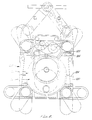
- the dolly 102 includes a dolly chassis 104 having a generally round pedestal opening 106 (Figs. 2 and 8) extending through the dolly chassis 104 for receiving and supporting the pedestal 101. Three or four recessed mounting positions with threaded holes are provided around the opening 106 for accepting and securing the pedestal 101 into the dolly 102, while maintaining a generally flat dolly deck surface.
- pivotally attached to the dolly chassis 104 are chassis legs, described herein as the front left leg 108; the front right leg 110; the rear right leg 112; and the rear left leg 114.
- the rear legs 112 and 114 can be pivoted on the dolly chassis 104 into leg positions A, B, and C.
- the front legs 108 and 110 may be pivoted into leg positions D, E and F. Other leg positions may also be used.
- the dolly With the rear dolly legs in position B and the front dolly legs in position D, the dolly is in the straight ahead or narrowest width dolly configuration. With the rear dolly legs in position C and the front dolly legs in position E, the dolly is in the track position, i.e., the dolly is configured to roll on standard track having 24.56 inch (62.38 cm) centers. With the rear dolly legs in position A and the front dolly legs in position F, the dolly is in a simulated three-point suspension configuration, i.e., the camera dolly approximates a tripod suspension.
- the left rear-wheel king pin assembly 116 is described herein in detail.
- the wheel king pin assembly 116 generally comprises the structure to the left of line W-W in Fig. 3).
- the other wheel assemblies on the dolly 102 will have similar construction.
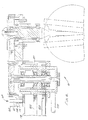
- a king pin 118 includes axles 119 extending at a dihedral angle. Wheels 120 are rotatably mounted on the axles 119. The wheels 120 are configured to roll either on the ground 122 or on a standard industry track rail.
- a king pin shaft 128 extends through a king pin shaft bearing 130 supported by a king pin ferrule 133.
- a spacer sleeve 127 spaces apart bearings 130 and 131 separating the bearings slightly more than the housing shoulder dimensions.
- a king pin sprocket 132 is mounted over a king pin sprocket bearing 134 on the king pin shaft 128.
- a wheel assembly steering locking bolt 136 preferably a socket head cap screw, extends through a cover plate 138 into a threaded hole in the top end of the king pin shaft 128.
- Cap 139 bears upon the cover plate 138 held by the locking bolt 136. As shown in Fig. 5, orientation of the plate 138 and its rotation is determined by the square end of the shaft 128 and the corresponding square hole in the plate 138.
- the wheels are steered to a straight ahead position.
- the cover plate 138 has three grooves or markings corresponding to the three leg settings. With the locking bolt 136 loosened, the king pin 118 is turned to align the appropriate marking on the cover plate 138 with a reference mark on the upper leg frame 142. The locking bolt 136 is then retightened.
- Each leg 108, 110, 112 and 114 comprises a lower leg frame 140 and an upper leg frame 142.
- the lower leg frame 140 has an elongated or oval opening 150 and slotted holes 152 for securing the king pin armature 154 to the lower leg frame 140.
- the slotted holes 152 allow the king pin armature 154 to be slidably positioned to adjust the appropriate tension in the leg belt 148.
- the king pin ferrule 133 is clamped into position using clamping bolts 146 after the position of the king pin ferrule 133 has been adjusted for proper tensioning of the leg belts, e.g. belt 148.
- Spacer sleeve 127 is of correct length to prevent the alignment clamping forces to be placed on the bearing balls thus preventing added friction.
- a hardened inner bearing frame 178 pivotally supports the leg 114 (and legs 108, 110, and 112) on the dolly chassis 104.
- the outer bearing frame 180 with the hardened sleeve 179 is fitted over the inner bearing frame 178 to form the bearing to pivotally mount the leg 114.
- Balls 182 are positioned within upper and lower annular openings 181 and 183 formed by the inner bearing frames 178 and the hardened sleeve 179 on the outer bearing frame 180.
- the shift assembly 160 can be made lightweight and compact. Seals 185 maintain lubricant within the bearings and keep contaminants out.
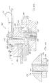
- a conventional steering sprocket 186 is rotatably mounted on the axle 173 by a bearing 187.
- a crab sprocket 194 is rotatably mounted on the axle 173 by crab sprocket bearings 196.
- a shaft drive sprocket 188 is irrotatably mounted on and fixed to the axle 173.
- a drive sleeve 189 is welded to the drive sprocket 188 and to the crab sprocket 194, or the sleeve 189 and sprockets 188 and 194 can be a single piece unit.
- Plate bearings 184 and 198 support the axle 173 within the inner bearing frame 178 and lower support plate 197.
- Retaining rings 202 secure the axle 173 vertically within the shift assembly 160 on the inner races of bearings 198 and 184.
- a lower plate 200 is secured to the lower end of the shaft 170 by cap screw 2G8.
- Lower shift pins 210 resting against the lower plate 200 extend through the lower support 197 and butt against middle shift pins 212 which extend through holes in the crab steering sprocket 194 and drive sprocket 188.
- Upper shift pins 214 rest against the middle shift pins 212 and extend through the conventional steering drive sprocket 186.
- the upper ends of the upper shift pins 214 are secured to the upper plate 172 which can rotate on a disc 175 that is secured to axle 173 by a pin 176.
- the shift pins 210, 212 and 214 preferably have tapered ends so that they can drive into and align the sprockets even when the holes in the sprockets are not yet perfectly aligned. This provides a larger "shifting window" in time, for shifting steering modes. As shown in Fig. 3, 2 sets of shift pins are provided 180° apart.
- a pivoting fork shift assembly 204 allows the lower plate 200 to be shifted from a lower or crab steering position (as shown in Fig. 3) wherein the middle shift pins 212 cause the drive sprocket 188 to be mechanically linked to the crab steering sprocket 194 -- to implement crab steering; to a second or conventional steering position wherein the lower plate 200 is shifted upwardly such that the crab sprocket 194 is mechanically linked to the fixed lower support 197 by the lower shift pins 210, and wherein the middle shift pins 212 cause the drive sprocket 188 to link up with and rotate with the conventional steering sprocket 186 -- to implement conventional steering.
- the drive sprocket 188 turns with the crab sprocket 194, while the conventional steering sprocket 186 remains fixed.
- the crab sprocket 194 remains fixed while the conventional steering sprocket 186 rotates with and is driven by the drive sprocket 188.
- Poke holes 215 through sprocket 166 and plate 172 allow the shift pins to be pushed out of the shift assembly 160 during maintenance.
- the lower plate 200 in both the left and right shift assemblies 160 and 161 are in the lower or crab position such that the conventional steering sprockets 186 and 187 are deactivated and the crab sprockets 194 and 195 are driven by the steering system 201.
- the shift knob 271 With the shift knob 271 in the "up" position, the plates 200 in the shift assemblies 160 and 161 are displaced upwardly such that the crab sprockets 194 and 195 are deactivated and the conventional steering sprockets 186 and 187 come into play.
- the conventional shift knob 270 and the crab shift knob 271 are on the rocker 272 linked to an extension shaft 273 extending through the dolly chassis to an arm linkage joined to a pivot shaft 275.
- the ends of the pivot shaft 275 are attached to a fork assembly 204 at the left and right shift assemblies 160 and 161.
- the fork assemblies 204 are pivotally joined to the (vertical) shafts 170 in the shift assemblies 160 and 161. Consequently angular rotation of the shaft 275 causes the vertical shafts 170 to shift between conventional and crab steering modes.
- the shaft 275 is positioned between the crab and conventional steering knobs 271 and 270. As one knob is depressed, the other is raised on the rocker 272 fixed to the top deck, as the dolly is shifted between conventional and crab modes.
- the rocker is preferably operated by foot.
- the steering shift assembly 160 and 161 allows the dolly 102 to be shifted from conventional steering, i.e., wherein the front wheels of the dolly would remain fixed in a "straight ahead" position with the rear wheels performing the steering, to a crab steering mode wherein all wheels remain parallel to each other and in the same direction, such that the dolly can "crab".
- FIGS 2 and 7 illustrate the steering system 201 of the dolly unit 102.
- the crab belt 220 continuously loops around and drivingly engages the crab sprockets 194 and front chassis sprockets 226, all of which are contained within the dolly chassis 104.
- the front chassis sprockets 226 are fixed to a shaft which drives the drive sprockets 106 in the front legs 108 and 110.
- Idler pulleys 250 are provided along the sides of the chassis for tensioning the crab belt 220.
- All of the belts in the steering system 201 are toothed rubber belts and have a flat back surface, such as Gates Rubber Co. POLYCHAIN GT belts.
- a primary sprocket 262 has a through square receptacle 260 adopted to receive a telescoping steering drive shaft 250 linked to the steering assembly of the pedestal, as further described below.
- a first ratio belt 224 drivably connects the primary sprocket 262 to an outer or second sprocket 236 on a two stage idler 232.
- a first or inner sprocket 234 of the two stage idler 232 is linked by the drive belt 218 to the shaft drive sprocket 188, as shown in Fig. 3.
- the conventional steering sprocket 186 is connected by the left conventional steering belt 216 to a steering corrector unit 300, and specifically to a first sprocket 312 on the corrector 300.
- a second sprocket 320 on the corrector 300 is linked by a right side conventional steering belt 242 to a right side conventional steering sprocket 187 within a right side shift assembly 161, as shown in Fig. 6.
- Idler pulleys are provided as shown in Fig. 2 to provide proper belt tensioning and for alignment purposes during manufacture or maintenance.
- the ratio between the steering wheel and the wheels, therefor, is 1 to 1.
- These sprockets can be machined down in height to maintain a compact and streamlined dolly chassis.
- Use of these sprockets with the Gates POLYCHAIN GT belts provides for exceptionally precise movement and handling of the steering system 201 which is very noticeable and desirable to the dolly grip or user.
- This steering system is also very quiet in operation permitting it to be freely used on sound stages without interfering with the audio aspects of television or motion picture production.
- the present embodiment uses toothed belts, chains, if made suitably quiet, could also be used.
- a leg locking pin system 163 is provided for each leg to lock the leg into its selected position.
- a crescent shaped handle 165 is joined to a pin 167 in a pin frame 169.
- a bushing or O-ring 171 in the frame 169 surrounds the pin 167 and provides damping to its movement.
- the pin 167 is releasably engageable through a bore in a flange of the hardened innerbearing frame 178 overlying the dolly chassis.
- An alternative arrangement, operated from underneath the dolly chassis, is shown in Fig. 11.
- the dolly chassis may be made as generally square or rectangular weldment with removable top and bottom plates 280 and 282 spaced apart by the frame 277, tubes 279, and ribs 284 (Fig. 8). Accessory pockets 285 are provided at the front and sides of the chassis to hold seats, platforms, pushbars, etc.
- a steering corrector or transmission unit 300 sets the proper relative angles of the rear wheels to achieve proper steering geometry.
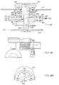
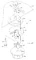
- the corrector unit 300 includes an eccentric hardened shaft 302 having an upper or first shaft section 304, a central section 324 and a lower or second shaft section 326 offset from the first shaft section 304.
- a threaded bore 306 extends into the first shaft section 304.
- a threaded bore 330 extends into the second shaft section 326.
- a top sprocket 312 is rotatably mounted onto the first shaft section 304 through a needle bearing 308.
- a belt flange 310 is integral with the top sprocket 312 and the top sprocket is held onto the first shaft section 304 by a snap ring 305.
- a top plate section 314 is rigidly attached to or integral with the top sprocket 312.
- a bottom sprocket 320 of the same size and pitch as the top sprocket 312 is rotatably mounted on the second shaft section 326 by a bearing 322.
- a belt flange 328 is integral with the bottom sprocket 320 which is held onto the second shaft section 326 by a snap ring 327.
- a lower plate 318 is rigidly attached to or integral with the bottom sprocket 320.
- a correction disk 316 is rotatably mounted on the central section 324 of the eccentric shaft 302 on a Glacier DU bushing or suitable alternate and between the upper plate 314 and lower plate 318.
- FIG. 10 402 represents the axis of the first section 304, 404 represents the axis of the central section 324, and 406 represents the axis of the second section 326 of the shaft 302. 408 is shown 90° to the alignment position.
- sprockets and disk oriented to the position 410 in Fig. 10, there is 0 correction, i.e. the wheels are straight ahead (the shifting position).
- Positions P1-P8 in Fig. 10 corresponds to the angular movements shown in Fig. 12A and 12B.
- Fig. 12B also shows the relationships of the intermediate wheel positions designated in Figs. 10 and 12A.
- the corrector 300 operates continuously to correct steering regardless of the increments shown or steering angle.
- the angles selected in Figs. 8 and 12 are examples selected for illustration purposes.
- an adjustable steering corrector 440 has a knob 442 on top of the dolly chassis.
- a shaft 446 has a first section 448, a central section 450 and a second section 452 offset from the central and first shaft sections.
- An eccentric drive collar 444 is rotatably mounted on the first shaft section 448.
- a central plate 454 is fixed to a floating hub 456 which is rotatably mounted onto the central shaft section 450.
- a top sprocket 458 is rotatably positioned over the eccentric drive collar 444.
- a bottom sprocket 460 is rotatably mounted on the lower shaft section 452.
- Upper and lower spacers 464 and 462 secure the corrector 440 within the dolly chassis.
- a pin 465 interconnects sliding dogs 466 and 468 which are radially slidable in slots in the plate sections 470 and 472 of the upper and lower sprockets 458 and 460.
- a collar pin 474 extends from the eccentric drive collar 444 into the floating hub 456.
- Fig. 16 shows a steering corrector 530 identical to the steering corrector 500 in Fig. 14, except for the design and mounting of the lower end.
- steering corrector 530 has an extended bottom cam 532 and extended hub 534, with the extended bottom cam 532 secured within a bearing 536.
- the bearing 536 is rigidly mounted within the dolly chassis.
- the chassis top deck surrounding the transmission 530 is slotted (.212 in. in the preferred design).
- a bushing having a square outside shape is provided around the transmission 530 to guide the upper end of the transmission in the slotted chassis deck.
- both the front wheels and back wheels are steered at the same angle, such that the camera support dolly can be steered and pushed laterally to the side, front or back, or at any desired angle, without changing the orientation of the camera 50.
Landscapes
- Engineering & Computer Science (AREA)
- General Engineering & Computer Science (AREA)
- Mechanical Engineering (AREA)
- Studio Devices (AREA)
- Steering-Linkage Mechanisms And Four-Wheel Steering (AREA)
- Catching Or Destruction (AREA)
- Handcart (AREA)
- Closed-Circuit Television Systems (AREA)
- Apparatus For Radiation Diagnosis (AREA)
- Filling Or Discharging Of Gas Storage Vessels (AREA)
- Fittings On The Vehicle Exterior For Carrying Loads, And Devices For Holding Or Mounting Articles (AREA)
Claims (13)
- Compensateur de guidage (300 ; 440 ; 500) comportant :un arbre (302 ; 446 ; 514) ayant un premier tronçon d'arbre (304 ; 448), un tronçon d'arbre central (324 ; 450) décalé du premier tronçon d'arbre, et un second tronçon d'arbre (326 ; 452) décalé du premier tronçon d'arbre et du tronçon d'arbre central ;un premier élément d'entraínement (312 ; 458 ; 508) fixé de manière rotative sur le premier tronçon d'arbre (302 ; 448) ;un second élément d'entraínement (320 ; 460 ; 526) fixé de manière rotative sur le second tronçon d'arbre (326 ; 452) ;un élément central (316 ; 454 ; 510) fixé de manière rotative sur le tronçon d'arbre central (324 ; 450) entre les premier et second éléments d'entraínement (312, 320 ; 458, 460 ; 508, 526) ; etdes moyens (336, 338, 340 ; 464, 466, 468 ; 512 ; 520) pour relier de manière pivotante lesdits premier et second éléments d'entraínement (312, 320 ; 458, 460 ; 508, 526) pour permettre un déplacement angulaire relatif entre eux.
- Compensateur de guidage selon la revendication 1, dans lequel lesdits premier et second éléments d'entraínement (312, 320 ; 458, 460) ont des diamètres approximativement égaux.
- Compensateur de guidage selon la revendication 1 ou 2, comportant de plus une première plaque d'élément d'entraínement (314 ; 470) reliée au premier élément d'entraínement (312 ; 458) et une seconde plaque d'élément d'entraínement (318 ; 472) reliée au second élément d'entraínement (316 ; 454).
- Compensateur de guidage selon la revendication 3, dans lequel lesdits moyens pour relier de manière pivotante comportent un ergot (340 ; 464 ; 520) s'étendant à partir d'un premier bloc de coulisseau (336 ; 468 ; 512) pouvant coulisser radialement dans une gorge (332) de la première plaque d'élément d'entraínement (314 ; 470), à travers un alésage de l'élément central (316 ; 454 ; 510) et relié à un second bloc de coulisseau (338 ; 466 ; 512) pouvant coulisser radialement dans une gorge (332) de la seconde plaque d'élément d'entraínement (318 ; 472).
- Compensateur de guidage selon la revendication 3 ou 4, dans lequel l'élément central est un disque (316 ; 454 ; 510) ayant un diamètre approximativement égal au diamètre des première et seconde plaques (314, 318 ; 470, 472).
- Compensateur de guidage selon l'une quelconque des revendications précédentes, dans lequel le premier élément d'entraínement et le second élément d'entraínement sont des roues dentées (312, 320 ; 458, 460 ; 508, 526).
- Compensateur de guidage selon l'une quelconque des revendications précédentes, dans lequel les premier et second éléments d'entraínement (312, 320) sont fixés sur l'arbre à l'aide d'anneaux d'encliquetage (305).
- Compensateur de guidage selon l'une quelconque des revendications précédentes, comportant de plus une caractéristique de correction d'angle réglable, comportant :un collier excentré (444) supporté de manière rotative sur le premier tronçon d'arbre (450), le premier élément d'entraínement (458) étant supporté de manière rotative autour du collier excentré (444) ;un moyeu (456) supporté de manière rotative sur le tronçon central (450) ; etune liaison (474) entre le collier excentré (444) et le moyeu (456).
- Compensateur de guidage selon la revendication 8, comportant de plus une plaque centrale (440) fixée sur le moyeu (456).
- Compensateur de guidage selon la revendication 8 ou 9, comportant de plus un bouton (442) fixé sur le collier excentré (444).
- Compensateur de guidage selon la revendication 10, comportant de plus un plateau supérieur de chariot (277), et dans lequel le bouton (442) est positionné sur le plateau supérieur de chariot.
- Correcteur d'angle de roue de guidage comportant :un moyeu décalé (514) ayant une première patte reliée à un premier côté d'un tronçon central et une seconde patte reliée à un second côté du tronçon central opposé au premier côté et décalée de la première patte ;une première came (506) supportée de manière pivotante autour de la première patte du moyeu décalé (514) ;une seconde came (522) supportée de manière pivotante autour de la seconde patte de moyeu décalé (514) ;une première roue dentée (508) supportée sur la première came (506) ;une seconde roue dentée (526) supportée sur la seconde came (522)un disque (510) supporté de manière rotative autour du tronçon central du moyeu décalé (514) entre les première et seconde roues dentées (508, 526) ;une liaison (520) s'étendant de manière coulissante entre les première et seconde roues dentées (508, 526) et à travers le disque (510) ;un montant d'engrenage (516) ayant une première extrémité et une seconde extrémité s'étendant à travers la première patte du moyeu décalé (514) ;des moyens (504) pour faire tourner le montant d'engrenage, agencés sur la première extrémité du montant d'engrenage ;un premier engrenage (518) situé sur la seconde extrémité du montant d'engrenage ; etun second engrenage (524) situé sur la seconde came (522) en prise avec le premier engrenage (518), de telle sorte que le déplacement des moyens (504) pour faire tourner entraíne la première came (506) à tourner et la seconde came (522) à tourner simultanément d'une quantité égale dans une direction opposée.
- Chariot de caméra (100) comportant un compensateur de guidage selon l'une quelconque des revendications 1 à 11 ou un correcteur de guidage selon la revendication 12.
Priority Applications (1)
| Application Number | Priority Date | Filing Date | Title |
|---|---|---|---|
| EP97106153A EP0785390A3 (fr) | 1990-10-01 | 1991-09-16 | Colonne de support de caméra |
Applications Claiming Priority (7)
| Application Number | Priority Date | Filing Date | Title |
|---|---|---|---|
| US07/591,525 US5197700A (en) | 1990-10-01 | 1990-10-01 | Camera pedestal |
| US07/591,524 US5174593A (en) | 1990-10-01 | 1990-10-01 | Camera dolly |
| US591525 | 1990-10-01 | ||
| US591524 | 1990-10-01 | ||
| US686823 | 1991-04-17 | ||
| US07/686,823 US5176401A (en) | 1990-10-01 | 1991-04-17 | Telescoping column |
| PCT/US1991/006708 WO1992006034A1 (fr) | 1990-10-01 | 1991-09-16 | Chariot de camera |
Related Child Applications (1)
| Application Number | Title | Priority Date | Filing Date |
|---|---|---|---|
| EP97106153A Division EP0785390A3 (fr) | 1990-10-01 | 1991-09-16 | Colonne de support de caméra |
Publications (3)
| Publication Number | Publication Date |
|---|---|
| EP0555314A1 EP0555314A1 (fr) | 1993-08-18 |
| EP0555314A4 EP0555314A4 (en) | 1995-11-02 |
| EP0555314B1 true EP0555314B1 (fr) | 1998-05-06 |
Family
ID=27416613
Family Applications (2)
| Application Number | Title | Priority Date | Filing Date |
|---|---|---|---|
| EP97106153A Ceased EP0785390A3 (fr) | 1990-10-01 | 1991-09-16 | Colonne de support de caméra |
| EP91919517A Expired - Lifetime EP0555314B1 (fr) | 1990-10-01 | 1991-09-16 | Chariot de camera |
Family Applications Before (1)
| Application Number | Title | Priority Date | Filing Date |
|---|---|---|---|
| EP97106153A Ceased EP0785390A3 (fr) | 1990-10-01 | 1991-09-16 | Colonne de support de caméra |
Country Status (6)
| Country | Link |
|---|---|
| EP (2) | EP0785390A3 (fr) |
| AT (1) | ATE165793T1 (fr) |
| AU (3) | AU654304B2 (fr) |
| CA (1) | CA2093121A1 (fr) |
| DE (1) | DE69129369T2 (fr) |
| WO (1) | WO1992006034A1 (fr) |
Cited By (2)
| Publication number | Priority date | Publication date | Assignee | Title |
|---|---|---|---|---|
| DE102007020980A1 (de) * | 2007-04-27 | 2008-10-30 | Vincent Botsch | Akkufach/Tiefplattform für Kamerawagen |
| US11097757B2 (en) | 2019-08-28 | 2021-08-24 | Filemon Aguirre | Load-bearing assembly |
Families Citing this family (30)
| Publication number | Priority date | Publication date | Assignee | Title |
|---|---|---|---|---|
| GB2274176B (en) * | 1993-01-12 | 1996-01-24 | Vinten Group Plc | Improvements in or relating to camera pedestals |
| EP0775664A2 (fr) | 1993-07-23 | 1997-05-28 | Leonard Studio Equipment Inc. | Chariot de caméra |
| GB9322770D0 (en) * | 1993-11-04 | 1993-12-22 | Grip House Ltd | Dolly |
| FR2725050A1 (fr) * | 1994-09-23 | 1996-03-29 | Ogusta | Chariot mobile pour camera de prise de vue cinematographique |
| WO2005039477A1 (fr) * | 2003-10-27 | 2005-05-06 | Robert John Tough | Dispositif a roues et systeme de direction associe |
| DE102004063563B4 (de) * | 2004-12-30 | 2022-05-25 | Grip Factory Munich Gmbh | Kamerawagen mit Lenkgetriebe |
| US9211895B2 (en) * | 2013-12-19 | 2015-12-15 | Chapman/Leonard Studio Equipment, Inc. | Camera dolly |
| CN104061407B (zh) * | 2014-06-13 | 2017-01-25 | 联想(北京)有限公司 | 一种移动机器人 |
| CN106555920B (zh) * | 2015-09-18 | 2019-08-23 | 广东实联医疗器械有限公司 | 一种医用万向摄像移动台车设备 |
| WO2018157396A1 (fr) * | 2017-03-03 | 2018-09-07 | 核动力运行研究所 | Dispositif d'inspection vidéo à utiliser avec des consoles de support suspendu |
| CN107575708A (zh) * | 2017-07-18 | 2018-01-12 | 响水县恒泰纺织有限公司 | 一种纺织机械支撑架 |
| CN107900990B (zh) * | 2017-11-06 | 2020-06-23 | 上海理工大学 | 基于视觉的智能机械臂物体抓取移动工作台 |
| CN111254066B (zh) * | 2018-12-03 | 2023-05-05 | 长春长光华大智造测序设备有限公司 | 一种成像调节装置和高通量基因测序仪 |
| CN110375166A (zh) * | 2019-06-26 | 2019-10-25 | 苏州金螳螂怡和科技有限公司 | 一种行人卡口抓拍系统 |
| CN111365586A (zh) * | 2020-03-05 | 2020-07-03 | 商洛学院 | 一种便于调节的机器学习的数据采集设备支架及方法 |
| DE102020118079A1 (de) | 2020-07-09 | 2022-01-13 | SINECTRO Ltd. | Fahrbare Einrichtung zum Bewegen eines Aufnahmegeräts |
| CN112061196A (zh) * | 2020-07-28 | 2020-12-11 | 李咏梅 | 一种医院用手推车 |
| CN114838269A (zh) * | 2021-02-01 | 2022-08-02 | 南京浦和数据有限公司 | 一种新型地铁员工执岗行为视频采集装置 |
| CN112923214A (zh) * | 2021-03-10 | 2021-06-08 | 中国科学院长春光学精密机械与物理研究所 | 一种车载光电测量设备落地对中装置 |
| CN113719732A (zh) * | 2021-09-18 | 2021-11-30 | 姚益林 | 一种户外斜坡自动平衡设备 |
| CN114135772B (zh) * | 2021-12-09 | 2022-06-17 | 山东柏远复合材料科技股份有限公司 | 一种多地形自适应测绘设备 |
| CN114216029B (zh) * | 2022-02-21 | 2022-05-03 | 金田产业发展(山东)集团有限公司 | 一种建筑设计用现场勘测装置 |
| CN114673893B (zh) * | 2022-04-21 | 2024-08-13 | 环胜电子(深圳)有限公司 | 定位模块及支架装置 |
| CN114542922A (zh) * | 2022-04-26 | 2022-05-27 | 国网山东省电力公司潍坊市寒亭区供电公司 | 一种变电站巡检装置 |
| KR102723796B1 (ko) * | 2022-05-23 | 2024-10-29 | 김태웅 | 3d 스캔 장치 |
| CN114791298B (zh) * | 2022-06-17 | 2022-09-16 | 江苏普达迪泰科技有限公司 | 一种升降式视觉测量车 |
| CN115031117B (zh) * | 2022-08-10 | 2022-10-28 | 徐州太平洋印务有限公司 | 一种用于印刷机的可调节支撑底座 |
| CN116471385B (zh) * | 2023-06-20 | 2023-09-08 | 四川三思德科技有限公司 | 一种野生动物保护区的行踪监控方法及系统 |
| CN118564806A (zh) * | 2024-07-03 | 2024-08-30 | 新疆疆天航空科技有限公司 | 一种农业遥感观测系统 |
| CN119155531B (zh) * | 2024-11-18 | 2025-01-07 | 厦门软云网络科技有限公司 | 一种自带补光功能的实时直播设备 |
Family Cites Families (21)
| Publication number | Priority date | Publication date | Assignee | Title |
|---|---|---|---|---|
| DD39462A (fr) * | ||||
| US2842376A (en) * | 1954-08-13 | 1958-07-08 | Krilanovich Steve | Wheel steering mechanism for camera dollies and the like |
| DE1555084A1 (de) * | 1966-03-07 | 1971-02-04 | Renato Castellani | Schirmstaender fuer Kraftfahrzeuge |
| DE1555048A1 (de) * | 1966-10-26 | 1970-10-08 | Colortran Ind Inc | Camera Crab Dolly |
| CH447839A (de) * | 1967-02-08 | 1967-11-30 | Sig Schweiz Industrieges | Lenkeinrichtung für Flurfördergeräte |
| US3682424A (en) * | 1969-07-16 | 1972-08-08 | Winton C Strumpell | Transportable camera pedestal |
| US4003584A (en) * | 1974-09-03 | 1977-01-18 | Sante Zelli | Dolly with articulated and steerable wheels |
| GB1530332A (en) * | 1976-03-13 | 1978-10-25 | Vinten Ltd | Balanced portable pedestals |
| US4257619A (en) * | 1978-09-26 | 1981-03-24 | Fisher James L | Variable ratio rotary positioning mechanism and camera dolly steering mechanism embodying same |
| SU977370A1 (ru) * | 1979-07-30 | 1982-11-30 | Предприятие П/Я Г-4617 | Гидравлический домкрат |
| IT1164702B (it) * | 1979-09-18 | 1987-04-15 | Sante Zelli | Perfezionamento nei dispositivo elevatori telescopici particolarmente per carrelli per riprese cinetelevisive |
| HU186104B (en) * | 1982-08-10 | 1985-06-28 | Arpad Beres | Energy storing frame suitable for moving equipments |
| DE3434386A1 (de) * | 1984-09-19 | 1986-03-27 | Sachtler GmbH Filmtechnische Geräte, 8046 Garching | Film- oder fernsehkamerastativ |
| DE3600971A1 (de) * | 1985-02-08 | 1987-07-16 | Sachtler Filmtech Geraete | Hoehenverstellbare saeule, insbesondere mittelsaeule fuer ein stativ zur aufnahme einer film- oder fernsehkamera |
| DE3504362C1 (de) * | 1985-02-08 | 1986-06-12 | Sachtler GmbH Filmtechnische Geräte, 8046 Garching | Hoehenverstellbare Saeule,insbesondere Mittelsaeule fuer ein Stativ zur Aufnahme einer Film- oder Fernsehkamera |
| JPS61256055A (ja) * | 1985-05-09 | 1986-11-13 | Toshiba Corp | 駆動機構 |
| US4757970A (en) * | 1985-05-17 | 1988-07-19 | Shotoku Ltd. | Balancing mechanism in pedestal carrying television camera |
| JPH0833632B2 (ja) * | 1987-04-10 | 1996-03-29 | コニカ株式会社 | 形成される色素の分光吸収特性が良好なハロゲン化銀写真感光材料 |
| GB8821791D0 (en) * | 1988-09-16 | 1988-10-19 | Vinten Ltd | Pneumatic spring |
| US5318313A (en) * | 1990-10-01 | 1994-06-07 | Leonard Studio Equipment, Inc. | Camera dally and pedestal |
| GB9601249D0 (en) * | 1996-01-23 | 1996-03-27 | Vitec Group Plc | Improvements in or relating to camera pedestals |
-
1991
- 1991-09-16 AT AT91919517T patent/ATE165793T1/de not_active IP Right Cessation
- 1991-09-16 DE DE69129369T patent/DE69129369T2/de not_active Expired - Fee Related
- 1991-09-16 WO PCT/US1991/006708 patent/WO1992006034A1/fr not_active Ceased
- 1991-09-16 AU AU88654/91A patent/AU654304B2/en not_active Ceased
- 1991-09-16 EP EP97106153A patent/EP0785390A3/fr not_active Ceased
- 1991-09-16 CA CA002093121A patent/CA2093121A1/fr not_active Abandoned
- 1991-09-16 EP EP91919517A patent/EP0555314B1/fr not_active Expired - Lifetime
-
1994
- 1994-11-07 AU AU77680/94A patent/AU677439B2/en not_active Ceased
-
1997
- 1997-07-23 AU AU30138/97A patent/AU688243B2/en not_active Ceased
Cited By (2)
| Publication number | Priority date | Publication date | Assignee | Title |
|---|---|---|---|---|
| DE102007020980A1 (de) * | 2007-04-27 | 2008-10-30 | Vincent Botsch | Akkufach/Tiefplattform für Kamerawagen |
| US11097757B2 (en) | 2019-08-28 | 2021-08-24 | Filemon Aguirre | Load-bearing assembly |
Also Published As
| Publication number | Publication date |
|---|---|
| WO1992006034A1 (fr) | 1992-04-16 |
| DE69129369D1 (de) | 1998-06-10 |
| AU688243B2 (en) | 1998-03-05 |
| AU654304B2 (en) | 1994-11-03 |
| AU3013897A (en) | 1997-10-02 |
| DE69129369T2 (de) | 1999-01-21 |
| AU8865491A (en) | 1992-04-28 |
| AU677439B2 (en) | 1997-04-24 |
| EP0555314A1 (fr) | 1993-08-18 |
| EP0555314A4 (en) | 1995-11-02 |
| AU7768094A (en) | 1995-02-02 |
| ATE165793T1 (de) | 1998-05-15 |
| EP0785390A3 (fr) | 1998-04-29 |
| CA2093121A1 (fr) | 1992-04-02 |
| EP0785390A2 (fr) | 1997-07-23 |
Similar Documents
| Publication | Publication Date | Title |
|---|---|---|
| EP0555314B1 (fr) | Chariot de camera | |
| US5174593A (en) | Camera dolly | |
| CA2327089C (fr) | Chariot de camera | |
| US5490684A (en) | Split chassis camera pedestal | |
| CA2936425C (fr) | Chariot de camera | |
| US5375863A (en) | Electronic steering mode shifter | |
| US5492353A (en) | Wheel suspension for a camera dolly | |
| US7891888B2 (en) | Camera slider system | |
| US6478427B1 (en) | Crane for a camera | |
| US9050985B1 (en) | Camera dolly | |
| CA2946239C (fr) | Base mobile destinee a une grue de camera | |
| CA2151744A1 (fr) | Chariot pour fleche de grue de camera | |
| CA2443596C (fr) | Systeme de roues pour chariot de camera | |
| US5730450A (en) | Push/steering bar for a camera pedestal | |
| US11733595B2 (en) | Mobile device for moving a recording apparatus | |
| US5609108A (en) | Track wheel kingpin system for a camera dolly | |
| US20060049593A1 (en) | Angle adjustable camber | |
| EP1068097B1 (fr) | Bras de chariot de camera | |
| AU681301B2 (en) | Camera dolly arm attachment | |
| WO2007145543A1 (fr) | Appareil de support de caméra |
Legal Events
| Date | Code | Title | Description |
|---|---|---|---|
| PUAI | Public reference made under article 153(3) epc to a published international application that has entered the european phase |
Free format text: ORIGINAL CODE: 0009012 |
|
| 17P | Request for examination filed |
Effective date: 19930401 |
|
| AK | Designated contracting states |
Kind code of ref document: A1 Designated state(s): AT BE CH DE DK ES FR GB GR IT LI LU NL SE |
|
| A4 | Supplementary search report drawn up and despatched | ||
| AK | Designated contracting states |
Kind code of ref document: A4 Designated state(s): AT BE CH DE DK ES FR GB GR IT LI LU NL SE |
|
| 17Q | First examination report despatched |
Effective date: 19960430 |
|
| GRAG | Despatch of communication of intention to grant |
Free format text: ORIGINAL CODE: EPIDOS AGRA |
|
| GRAG | Despatch of communication of intention to grant |
Free format text: ORIGINAL CODE: EPIDOS AGRA |
|
| GRAH | Despatch of communication of intention to grant a patent |
Free format text: ORIGINAL CODE: EPIDOS IGRA |
|
| GRAH | Despatch of communication of intention to grant a patent |
Free format text: ORIGINAL CODE: EPIDOS IGRA |
|
| GRAH | Despatch of communication of intention to grant a patent |
Free format text: ORIGINAL CODE: EPIDOS IGRA |
|
| GRAA | (expected) grant |
Free format text: ORIGINAL CODE: 0009210 |
|
| AK | Designated contracting states |
Kind code of ref document: B1 Designated state(s): AT BE CH DE DK ES FR GB GR IT LI LU NL SE |
|
| DX | Miscellaneous (deleted) | ||
| PG25 | Lapsed in a contracting state [announced via postgrant information from national office to epo] |
Ref country code: IT Free format text: LAPSE BECAUSE OF FAILURE TO SUBMIT A TRANSLATION OF THE DESCRIPTION OR TO PAY THE FEE WITHIN THE PRESCRIBED TIME-LIMIT;WARNING: LAPSES OF ITALIAN PATENTS WITH EFFECTIVE DATE BEFORE 2007 MAY HAVE OCCURRED AT ANY TIME BEFORE 2007. THE CORRECT EFFECTIVE DATE MAY BE DIFFERENT FROM THE ONE RECORDED. Effective date: 19980506 Ref country code: ES Free format text: THE PATENT HAS BEEN ANNULLED BY A DECISION OF A NATIONAL AUTHORITY Effective date: 19980506 Ref country code: LI Free format text: LAPSE BECAUSE OF FAILURE TO SUBMIT A TRANSLATION OF THE DESCRIPTION OR TO PAY THE FEE WITHIN THE PRESCRIBED TIME-LIMIT Effective date: 19980506 Ref country code: GR Free format text: LAPSE BECAUSE OF FAILURE TO SUBMIT A TRANSLATION OF THE DESCRIPTION OR TO PAY THE FEE WITHIN THE PRESCRIBED TIME-LIMIT Effective date: 19980506 Ref country code: CH Free format text: LAPSE BECAUSE OF FAILURE TO SUBMIT A TRANSLATION OF THE DESCRIPTION OR TO PAY THE FEE WITHIN THE PRESCRIBED TIME-LIMIT Effective date: 19980506 Ref country code: AT Free format text: LAPSE BECAUSE OF FAILURE TO SUBMIT A TRANSLATION OF THE DESCRIPTION OR TO PAY THE FEE WITHIN THE PRESCRIBED TIME-LIMIT Effective date: 19980506 |
|
| REF | Corresponds to: |
Ref document number: 165793 Country of ref document: AT Date of ref document: 19980515 Kind code of ref document: T |
|
| REG | Reference to a national code |
Ref country code: CH Ref legal event code: EP |
|
| REF | Corresponds to: |
Ref document number: 69129369 Country of ref document: DE Date of ref document: 19980610 |
|
| ET | Fr: translation filed | ||
| PG25 | Lapsed in a contracting state [announced via postgrant information from national office to epo] |
Ref country code: SE Free format text: LAPSE BECAUSE OF FAILURE TO SUBMIT A TRANSLATION OF THE DESCRIPTION OR TO PAY THE FEE WITHIN THE PRESCRIBED TIME-LIMIT Effective date: 19980806 Ref country code: DK Free format text: LAPSE BECAUSE OF FAILURE TO SUBMIT A TRANSLATION OF THE DESCRIPTION OR TO PAY THE FEE WITHIN THE PRESCRIBED TIME-LIMIT Effective date: 19980806 |
|
| PG25 | Lapsed in a contracting state [announced via postgrant information from national office to epo] |
Ref country code: LU Free format text: LAPSE BECAUSE OF NON-PAYMENT OF DUE FEES Effective date: 19980916 |
|
| PG25 | Lapsed in a contracting state [announced via postgrant information from national office to epo] |
Ref country code: BE Free format text: LAPSE BECAUSE OF NON-PAYMENT OF DUE FEES Effective date: 19980930 |
|
| REG | Reference to a national code |
Ref country code: CH Ref legal event code: PL |
|
| PLBE | No opposition filed within time limit |
Free format text: ORIGINAL CODE: 0009261 |
|
| STAA | Information on the status of an ep patent application or granted ep patent |
Free format text: STATUS: NO OPPOSITION FILED WITHIN TIME LIMIT |
|
| BERE | Be: lapsed |
Owner name: CHAPMAN LEONARD T. Effective date: 19980930 |
|
| PG25 | Lapsed in a contracting state [announced via postgrant information from national office to epo] |
Ref country code: NL Free format text: LAPSE BECAUSE OF NON-PAYMENT OF DUE FEES Effective date: 19990401 |
|
| 26N | No opposition filed | ||
| NLV4 | Nl: lapsed or anulled due to non-payment of the annual fee |
Effective date: 19990401 |
|
| REG | Reference to a national code |
Ref country code: GB Ref legal event code: IF02 |
|
| PGFP | Annual fee paid to national office [announced via postgrant information from national office to epo] |
Ref country code: FR Payment date: 20030909 Year of fee payment: 13 |
|
| PGFP | Annual fee paid to national office [announced via postgrant information from national office to epo] |
Ref country code: DE Payment date: 20030925 Year of fee payment: 13 |
|
| PGFP | Annual fee paid to national office [announced via postgrant information from national office to epo] |
Ref country code: GB Payment date: 20040915 Year of fee payment: 14 |
|
| PG25 | Lapsed in a contracting state [announced via postgrant information from national office to epo] |
Ref country code: DE Free format text: LAPSE BECAUSE OF NON-PAYMENT OF DUE FEES Effective date: 20050401 |
|
| PG25 | Lapsed in a contracting state [announced via postgrant information from national office to epo] |
Ref country code: FR Free format text: LAPSE BECAUSE OF NON-PAYMENT OF DUE FEES Effective date: 20050531 |
|
| REG | Reference to a national code |
Ref country code: FR Ref legal event code: ST |
|
| PG25 | Lapsed in a contracting state [announced via postgrant information from national office to epo] |
Ref country code: GB Free format text: LAPSE BECAUSE OF NON-PAYMENT OF DUE FEES Effective date: 20050916 |
|
| GBPC | Gb: european patent ceased through non-payment of renewal fee |
Effective date: 20050916 |