EP0555367B1 - Systeme de lentilles de contact pour diagnostic par ophtalmoscopie indirecte - Google Patents
Systeme de lentilles de contact pour diagnostic par ophtalmoscopie indirecte Download PDFInfo
- Publication number
- EP0555367B1 EP0555367B1 EP92900048A EP92900048A EP0555367B1 EP 0555367 B1 EP0555367 B1 EP 0555367B1 EP 92900048 A EP92900048 A EP 92900048A EP 92900048 A EP92900048 A EP 92900048A EP 0555367 B1 EP0555367 B1 EP 0555367B1
- Authority
- EP
- European Patent Office
- Prior art keywords
- eye
- fundus
- anterior
- lens element
- lens
- Prior art date
- Legal status (The legal status is an assumption and is not a legal conclusion. Google has not performed a legal analysis and makes no representation as to the accuracy of the status listed.)
- Expired - Lifetime
Links
- 238000009540 indirect ophthalmoscopy Methods 0.000 title claims abstract description 44
- 238000005286 illumination Methods 0.000 claims abstract description 21
- 230000004075 alteration Effects 0.000 claims description 22
- 238000003780 insertion Methods 0.000 claims description 2
- 230000037431 insertion Effects 0.000 claims description 2
- 238000009958 sewing Methods 0.000 claims description 2
- 230000003287 optical effect Effects 0.000 abstract description 23
- 238000001356 surgical procedure Methods 0.000 abstract description 5
- 210000004087 cornea Anatomy 0.000 description 20
- 238000000034 method Methods 0.000 description 11
- 238000013461 design Methods 0.000 description 8
- 230000002093 peripheral effect Effects 0.000 description 8
- 210000001747 pupil Anatomy 0.000 description 8
- 210000003128 head Anatomy 0.000 description 6
- 201000009310 astigmatism Diseases 0.000 description 4
- 238000012937 correction Methods 0.000 description 3
- 230000005499 meniscus Effects 0.000 description 3
- 230000000593 degrading effect Effects 0.000 description 2
- 238000003754 machining Methods 0.000 description 2
- 239000000463 material Substances 0.000 description 2
- 239000004033 plastic Substances 0.000 description 2
- 229920003023 plastic Polymers 0.000 description 2
- 239000006117 anti-reflective coating Substances 0.000 description 1
- 230000009286 beneficial effect Effects 0.000 description 1
- 230000005540 biological transmission Effects 0.000 description 1
- 230000015572 biosynthetic process Effects 0.000 description 1
- 150000001875 compounds Chemical class 0.000 description 1
- 230000007423 decrease Effects 0.000 description 1
- 230000003247 decreasing effect Effects 0.000 description 1
- 238000003745 diagnosis Methods 0.000 description 1
- 238000002405 diagnostic procedure Methods 0.000 description 1
- 230000000694 effects Effects 0.000 description 1
- 230000004438 eyesight Effects 0.000 description 1
- 238000001914 filtration Methods 0.000 description 1
- 230000004313 glare Effects 0.000 description 1
- 239000011521 glass Substances 0.000 description 1
- 239000003292 glue Substances 0.000 description 1
- 230000001771 impaired effect Effects 0.000 description 1
- 230000014759 maintenance of location Effects 0.000 description 1
- 238000004519 manufacturing process Methods 0.000 description 1
- 238000012986 modification Methods 0.000 description 1
- 230000004048 modification Effects 0.000 description 1
- ORQBXQOJMQIAOY-UHFFFAOYSA-N nobelium Chemical compound [No] ORQBXQOJMQIAOY-UHFFFAOYSA-N 0.000 description 1
- 239000005304 optical glass Substances 0.000 description 1
- 230000037361 pathway Effects 0.000 description 1
- 229920003229 poly(methyl methacrylate) Polymers 0.000 description 1
- 239000004926 polymethyl methacrylate Substances 0.000 description 1
- 230000000750 progressive effect Effects 0.000 description 1
- 230000009467 reduction Effects 0.000 description 1
- 208000014733 refractive error Diseases 0.000 description 1
- 230000000717 retained effect Effects 0.000 description 1
- 210000001525 retina Anatomy 0.000 description 1
- 210000003786 sclera Anatomy 0.000 description 1
- 238000010871 transoral laser microsurgery Methods 0.000 description 1
Images


Classifications
-
- A—HUMAN NECESSITIES
- A61—MEDICAL OR VETERINARY SCIENCE; HYGIENE
- A61B—DIAGNOSIS; SURGERY; IDENTIFICATION
- A61B3/00—Apparatus for testing the eyes; Instruments for examining the eyes
- A61B3/10—Objective types, i.e. instruments for examining the eyes independent of the patients' perceptions or reactions
- A61B3/117—Objective types, i.e. instruments for examining the eyes independent of the patients' perceptions or reactions for examining the anterior chamber or the anterior chamber angle, e.g. gonioscopes
-
- A—HUMAN NECESSITIES
- A61—MEDICAL OR VETERINARY SCIENCE; HYGIENE
- A61B—DIAGNOSIS; SURGERY; IDENTIFICATION
- A61B3/00—Apparatus for testing the eyes; Instruments for examining the eyes
- A61B3/10—Objective types, i.e. instruments for examining the eyes independent of the patients' perceptions or reactions
- A61B3/12—Objective types, i.e. instruments for examining the eyes independent of the patients' perceptions or reactions for looking at the eye fundus, e.g. ophthalmoscopes
- A61B3/125—Objective types, i.e. instruments for examining the eyes independent of the patients' perceptions or reactions for looking at the eye fundus, e.g. ophthalmoscopes with contact lenses
Definitions
- the present invention relates to a diagnostic indirect ophthalmoscopy contact lens device. More particularly, the invention relates to a diagnostic contact lens for indirect ophthalmoscopy which operates both as an improved condensing lens device for conveyance of a light from an indirect ophthalmoscope or slit lamp biomicroscope through the pupil and onto the fundus of an examined eye.
- the lens device also acts to form a aberration free and extremely wide field inverted or upright real aerial image of the fundus of the eye.
- Diagnostic lenses for indirect ophthalmoscopy are used by ophthalmologists and optometrists to observe the fundus of an eye for diagnostic or surgical procedures.
- Various known ophthalmoscopic lenses or other diagnostic devices have lenses for conveying light from a source onto the fundus of an eye and forming an aerial image of the fundus.
- Patent No. 3,954,329 there is shown an ophthalmoscope for viewing a fundus which includes a contact lens which directly contacts the cornea of the eye as well as a posterior or field lens spaced from the contact lens and supported in a housing relative thereto.
- This invention employs both direct illumination of the fundus of the eye as well as transillumination to obtain wide angle viewing of the fundus.
- Other similar systems in Patent Nos are also used in Patent Nos.
- U. S. Patent No. 4,728,183 to Heacock utilizes a contact lens element situated relative to an entry lens in a holder. It is stated that the contact lens element is designed such that the light rays emerging from the patient's eye exit the contact lens in a parallel relationship which are then directed to the entry lens.
- the entry lens is an aspheric lens which forms an aerial image of the fundus.
- This patent thus describes an ophthalmic lens system wherein the contact lens has two spherical surfaces, designed such that light rays emerging from the patient's eye and through the contact lens are substantially parallel, rather than convergent, as they exit in an anterior direction from the contact lens.
- the aspheric entry lens of this invention will be inadequate in some circumstances as an image forming lens as it will be insufficient for correcting field curvature and aberrations due in part to the spherical design of the contact lens.
- the contact lens design has failed to account for the corrective quality of the aspheric cornea of the eye itself and may tend to degrade the image of the fundus of the eye.
- the indirect ophthalmoscopy diagnostic contact lens system should function as a condensing lens for converging light from the light source of a biomicroscope through the pupil of an examined eye onto the fundus of the eye.
- the lens system should provide the optical properties to avoid aberrations normally associated with spherical lenses.
- US-A-4728183 forms the pre-characterising portions of claim 1 and claim 3.
- My prior WO91/06240 falls within the terms of Art 54 and is therefore not relevant to the question of inventive step.
- an indirect ophthalmoscopy lens device used to observe the fundus of the eye comprising:
- the flange portion may further comprise:
- an indirect ophthalmoscopy device used to observe the fundus of the eye comprising:
- I therefore provide an improved diagnostic contact lens for indirect ophthalmoscopy which simultaneously functions as both an improved condensing lens as well as an improved image forming lens.
- the lens system acts to converge light from the source of a slit lamp biomicroscope or other microscope through the pupil of an examined eye, projecting a distortion free, clear and focused image of the aperture of the light source on to the fundus of an examined eye.
- the lens system also produces an extremely wide field inverted real aerial image of the fundus of the eye which is essentially free of field curvature, lateral astigmatism and distortion, viewed either monocularly or binocularly through a biomicroscope.
- the preferred embodiment of the invention may include an aspheric corneal contact element of positive refractive power, a high powered biconvex aspheric anterior lens, and a generally conically shaped housing securing and interconnecting both lens components while preventing extraneous light, moisture, and dirt from entering the interior optical area.
- the contact element includes an aspheric anterior surface of the contact element that not only contributes to the improved optical performance of the unit as both a condensing lens and image forming lens, but in addition, because of the continuous and progressive reduction in curvature peripheralward, allows for surfaces with both short apical radii and relatively large diameters.
- the concave posterior surface of the contact element may also be aspheric, thereby, facilitating an improved corneal fit as well as translateral movement of the lens unit on the eye.
- the biconvex aspheric anterior element is co-acting with the aspheric contact element in such a way as to provide optimum condensing and image forming properties. It is desired that each of the two or more lens elements have significant light converging properties and be aspheric, and it is these features in addition to others that distinguish it from the prior art lenses and which provide improved performance and high optical resolution.
- the anterior lens element(s) may be very high powered lenses which allow for an extremely wide field of view as desired.
- the anterior lens element may have a refractive power chosen to optimize the field of view obtainable by the device in conjunction with the contact lens element.
- the dimensions of the device are extremely critical for maintaining the position of the device to enable indirect ophthalmoscopy without requiring manipulation by the physician.
- an extremely high powered lens may be utilized to maximize the field of view in accordance with the dimensions of the device.
- An upright aerial image may be formed by the diagnostic indirect ophthalmoscopy device by utilizing coaxial anterior lenses having refractive powers to enable reinverting the image formed by a combination of the lenses in the device.
- illuminating light may be provided in conjunction with the device so as to reduce the formation of reflections but to provide proper illumination of the fundus of the eye.
- the compound diagnostic indirect ophthalmoscopy contact lens 10 includes a generally conically shaped lens holder 12, providing means for securing and interconnecting a contact lens element 14 and at least one anterior lens element 16.
- the lens holder 12 also allows a means for digital manipulation of the unit when disposed against the eye 18 of the patient.
- Both the contact lens element 14 and the anterior element 16 may be made of homogenous transparent optical material, such as glass or plastic.
- the optical material may be treated to include light filtering properties for absorbing specific wavelengths of light, or other known treatment to obtain the desired optical properties.
- the contact lens element 14 be made of ophthalmic plastic, such as poly methyl methacrylate or cr39, and that the anterior element 16 be made of optical glass, such as Schott BK7.
- the contact lens element 14 is mounted in the small end of the housing unit 12 so as to extend outwardly therefrom to enable contact with the cornea of the eye.
- the anterior lens element 16 is mounted in the larger diameter end of housing 12 inwardly of the open end to protect the lens. Both surfaces of the anterior lens element 16 and the anterior surface of the contact lens element 14 may be coated with an anti-reflective coating to minimize reflections and increase light transmission.
- the contact lens element 14 may be secured in place with optical glue, by means of interlocking threads, or by other conventional means.
- the interior portion of the larger diameter end of the conically shaped housing includes a generally cylindrical portion 20 which is approximately .003" larger in diameter than the diameter of the anterior lens 16.
- the portion 20 provides a cylindrical cavity into which the anterior lens 16 may be fitted and with a secondary cylindrical inner diameter 22, approximately .040" smaller than the diameter of the interior lens 16, providing a shoulder on which the outer edge of the lens 16 is supported and spaced from the contact lens element 14.
- the depth of the primary cylinder is adequate to provide protection for the interior surface of the anterior lens 16 when affixed against the secondary cylindrical shoulder.
- the primary cylinder may be internally threaded at 24 to receive an externally threaded retaining ring 26 securing the anterior lens 16 in place against the secondary cylindrical shoulder 22.
- the threaded retaining ring systems are standard conventional means by which optical lenses are secured in lens housings.
- the contact element 14 and anterior element 16 both have positive refractive power and act in conjunction with one another to produce an extremely wide field of view of the fundus of an eye which is substantially free of optical aberrations.
- the anterior element 16 is designed as a biconvex lens having predetermined refractive properties to coact with the plus powered contact element in such a way as to produce a condensing lens system for projection of light from a biomicroscope light source to produce a clear image of the light source aperture on the fundus of the eye.
- Fig. 2 the light ray paths of the illumination system of a conventional slit lamp biomicroscope when used in conjunction with the lens system of the present invention are shown.
- the lens system of this invention has been designed to perform in an optimal fashion as a condensing lens for projecting a clear, sharply focused image of the aperture of the light source of a biomicroscope onto the fundus of an examined eye.
- light rays 50, 51 and 52 originating at a light source filament 53 are refracted by a condensing lens assembly 54 which directs the light rays towards the slit lamp aperture 56 which is situated at the back focus plane of condensing lens system 58.
- light rays 60, 61 and 62 proceed toward and are refracted by condensing lens system 58 and continue toward mirror 64 which reflects the light rays at approximately 45 degrees towards the image plane 40 where the light rays form an aerial image of the slit lamp aperture 56.
- the image plane 40 functions as a new light source wherein light rays 68, 69 and 70 proceed to and are refracted by the aspheric biconvex lens 16.
- the anterior biconvex lens 16 being a plus powered lens causes the light rays 68, 69 and 70 to converge towards the contact lens element 14 of the device.
- the contact lens element 14 may also be plus powered and thus cause the light rays to further converge toward the pupil 36 of the examined eye through the cornea 38.
- the light rays proceed through the eye and are focused as a clear image of the slit lamp aperture 56 onto the fundus of the examined eye 34 at points 72, 74 and 76.
- the condensing qualities of the lens system of the invention operate to transmit light rays from the light source onto the fundus of the eye without incurring optical aberrations which may be caused by typical lens systems.
- the plus powered meniscus contact lens element 14 as well as at least one plus powered biconvex anterior lens element 16 each contribute positive refractive power to the optical system and may have aspheric surfaces which coact with one another in such a way to provide optimum condensing and image forming properties.
- the lens system provides significant light converging properties along with aspheric surfaces which optimize the optical system to avoid aberrations especially at the periphery of the formed image.
- the lens system also enables an extremely wide field of view and illumination so as to avoid the use of transillumination techniques or the like.
- One of the novel features of this invention relates to the aspheric design of the contact lens element 14, where either the convex only or both the concave and convex surfaces are aspheric.
- the aspheric surfaces of revolution are of prolate type, decreasing in curvature from apex to periphery, and each of the two surfaces are on a common axis of revolution.
- An additional novel feature of this invention relates to the aspheric design of the biconvex lens element 16, where either or both the posterior and anterior surfaces are aspheric.
- r, e, A, B, C, F, G, and H are chosen such that light rays originating at the fundus 34 of the eye, exiting through the pupil 36 of the eye and passing through the aspheric contact lens element 14 and biconvex aspheric lens element 16 form an aerial image of the fundus of the eye anterior to the aspheric biconvex element 16 at plane 40.
- the image is substantially free of aberrations such as field curvature, lateral astigmatism, and distortion.
- the apical radius of curvature for each surface of the biconvex aspheric lens element 16 may range from 70mm to 5mm and may be in a reciprocal relationship with the apical radius of curvature of the opposite surface of element 16, ranging from .588 to 1.7 times its opposite surface radius value.
- values of e, representing apical eccentricity may range from 0.7 to 4.0
- coefficients A, B, C may range from -10.0 to 10.0
- exponents F, G, and H may range from .5 to 10.0.
- the contact lens element 14 has positive refractive power making it desirable to aspherize its convex anterior surface in order to minimize excess peripheral power and associated optical aberrations.
- the contact element 12 thereby aids the biconvex aspheric lens 14 in producing an aerial image free of aberrations.
- the concave posterior surface of the contact lens 12 may be aspherized to closely approximate the aspheric corneal contour, with an apical radius of curvature substantially the same as that of the anterior surface of the average cornea.
- the concave posterior surface is aspherized, it may be desirable to provide a peripheral slope of the lens which is equal to or less than that of the average cornea at an equivalent diameter, thereby minimizing the possibility of localized peripheral lens bearing and facilitating translational movement of the lens on the cornea.
- the apical radius of curvature, r may range from 3.5 to 9.0, and e, representing apical eccentricity, may range from 0.05 to 1.4, coefficients A, B, and C may range from -10.0 to 10.0 and exponents F, G, and H may range from .5 to 10.
- the apical radius of curvature, r may range from 6.5 to 9.0, and e, representing apical eccentricity may range from 0.0 to 1.2, coefficients A, B, C may range from -10.0 to 10.0 and exponents F, G, and H may range from .5 to 10.
- the diameter of the convex anterior surface may range from 6 to 16mm, while the diameter of the concave posterior surface may be varied, and is most preferably around 12.0mm.
- a peripheral portion of the contact element on the concave posterior surface may include a secondary peripheral curvature and overall may be as large as 17mm, with a diameter of 15.5mm being preferred.
- Center thickness of the contact element may range from 1.5mm to 10mm.
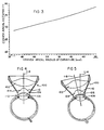
- the device 100 includes at least one anterior lens element 102 and a contact lens element 104 which is designed having an aspheric posterior concave surface 106.
- the concave posterior surface 106 of the contact element 104 is designed to closely approximate the aspheric contour of the cornea 108 of the examined eye over most of its surface.
- the concave posterior surface 106 of the contact element 104 is of prolate type, wherein the curvature decreases from the apex to the periphery of the lens.
- the device 100 functions as previously described to provide a condensing lens system for transmitting light from a light source onto the fundus of an eye as well as forming an aberration free, wide field image of the fundus when the device is on axis with the cornea of the eye at 114.
- the aspheric contact surface of the contact element 104 allows translational movement of the device 100 on the cornea surface with minimum localized peripheral lens bearing on the cornea. As seen in Fig. 5, translational movement of the device 100 to axis 116 is possible without incurring excessive localized lens bearing on the corneal surface 108 of the examined eye. It is also seen that the aspheric surface 106 generally maintains close contact with the cornea 108 throughout translational movement. The aspheric surface 106 of the contact element 104 will also function to inhibit the retention of bubbles between the contact element and the cornea of the eye which is a common problem in existing lens systems.
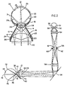
- the device 150 includes a housing member 152 providing a means for securing and interconnecting a contact lens element 154 and at least one anterior lens element 156 in proper relationship to form an aerial image of the fundus of the eye as well as for condensing illuminating light onto the fundus in a manner similar to that previously described.
- the lens holding housing 152 allows digital manipulation of the device when disposed against the eye of a patient to facilitate observation of the fundus by an examining physician.
- the contact lens element 154 in this embodiment may again include an aspheric anterior surface 158 if desired, and may also include an aspherical posterior surface 160 which is matched substantially to that of the anterior surface of the average cornea.
- both the posterior and anterior surfaces of the contact lens element 154 may be defined by the polynomial as described with reference to the embodiment of Fig. 1.
- the bi-convex anterior lens element 156 similarly may be provided with one or both surfaces thereof being aspherical and defined by the polynomial as described with reference to the anterior element of Fig. 1.
- Aspherizing the surfaces of the anterior element 156 may contribute to the minimization of aberrations to produce an image which is substantially free from aberrations such as field curvature, lateral astigmatism and distortion.
- one or both surfaces of the anterior lens element 156 may be spherical in shape, but combined with aspherical surfaces on the contact lens element or additional lens elements of the system to reduce excess peripheral power and associated optical aberrations.
- the device 150 also includes a reinverting prism structure generally indicated at 162, which may be a known configuration of a Pechan prism including two prism elements 164 and 166 which together function to erect the inverted image of the fundus produced by the image forming contact lens element 154 and anterior lens element 156.
- the field of view obtainable by the device 150 may be limited by the erecting prism 162 such that it is desired to maximize the field of view obtainable by the device.
- the image forming lenses comprising the contact lens element 154 and at least one anterior lens element 156 may have extremely high positive refractive power to provide significant light converging properties which will enable an extremely wide field of view for the system while providing optimum condensing and image forming properties.
- the contact lens element 154 may be a relatively thin, low power configuration, such as from 0 to 30 diopters or the like.
- the anterior lens element 156 may be a high powered lens element such as a 160-180 diopter lens.
- the contact lens 154 and anterior lens element 156 in combination may then contribute a desired amount of refractive power to achieve the desired field of view. It is apparent that the particular configuration of both the contact lens element 154 and anterior lens element 156 or additional anterior lens elements merely must be designed in conjunction with one another to provide the proper light converging characteristics necessary to achieve the optimum field of view in the system and can vary accordingly.
- the relative spacing between the contact lens element 154 and any anterior lens elements 156 will necessarily be chosen such that the lens elements are coaxial with the eye and perpendicular to the optical pathway and spaced relative to one another so as to properly form the aerial image in an image plane anterior to the lens elements.
- the image formed by the lens elements of the device 150 will be a real image which is substantially free of aberrations, but which is an inverted image and undesirable for various examination or surgical techniques.
- the erecting prism structure 162 may thus erect the inverted image produced by the lens system of device 150 without degrading the quality of the image produced by the system.
- Viewing of the upright image formed by the device 150 using an ophthalmoscope or slit lamp biomicroscope may then be performed, with focusing on the image accomplished by positioning a microscope head of the biomicroscope to view the upright image which will essentially be formed in the plane of a surface within the erecting prism structure 162.
- Fig. 7 the light path through the optical device 150 to yield an upright aerial image of the fundus of an eye is shown in more detail.
- homocentric bundles of diverging light rays from the points in the illuminated fundus will be directed to pass through the pupil of the eye so as to emerge from the cornea as homocentric bundles of light rays.
- An example of the homocentric bundle of parallel light rays is shown from a single point at 172 on the fundus 170 of the eye 168, but it should be understood that a large number of homocentric bundles of parallel light rays will be produced from the fundus 170.
- the light rays As the light rays emerge from the cornea, they will be incident upon the back surface of the contact lens element 154 to be refracted thereby if contact lens element 154 is of positive refractive power. Upon exiting the contact lens element, the light rays will be incident upon the anterior lens element 156 wherein they will be further refracted to form an inverted real image of the fundus in the anterior focal plane of the anterior lens element 156. The inverted image is directed to the erecting prism structure 162 comprising elements 164 and 166.
- a Pechan prism is utilized wherein the prism elements 164 and 166 are configured such that an image entering an entrance window 174 will be incident upon a surface 176 of the prism element 166 at an incidence angle so as to be reflected from this surface as indicated at 178.
- Surfaces of prism element 166 other than surface 176 may be mirrored such that the incident light rays 178 from surface 176 will be reflected back toward surface 176 at a proper incidence angle to pass through surface 176 into prism element 164.
- Light entering prism element 164 will be directed to an exit window 180 at an angle of incidence so as to be reflected off the surface and towards surfaces of prism element 164 wherein the image will essentially be erected to be incident upon surface 182 of prism element 164 at an incidence angle to be reflected outwardly of exit window 180 toward the viewing biomicroscope.
- the erecting nature of the prism structure as shown in the figure will thus produce an upright aerial image of the fundus as desired without degrading the quality of the image produced to any great extent.
- Figs 8 and 9 alternate embodiments of the device as seen in Fig. 6 are shown to obtain an extremely wide field of view from the device. It was been recognized when utilizing an erecting prism structure such as the Pechan prism shown in this embodiment of the device that the field of view may be limited thereby. As the homocentric bundles of parallel light rays from the fundus are directed toward the erecting prism structure, only those which are properly incident upon the reflective surfaces of the prism structure will be erected and directed toward the biomicroscope.
- the device 150 may further include an additional lens element 190 having a negative powered meniscus surface 192 which will add divergence to the homocentric bundles of light beams exiting the prism element 164 through exit window 180.
- the addition of negative refractive power to the system will act to slightly enlarge the formed upright aerial image of the fundus, and will additionally increase working distances relative to the biomicroscope to move the formed aerial image further from the device 150 toward the biomicroscope.
- an alternative embodiment accomplishing a similar goal may be provided by machining the exit window 180 of the prism element 164 so as to have a negative power meniscus which will add divergence to the exiting bundles of homocentric light beams therefrom.
- the effect of machining the exit window 180 will of course have to be taken into account in the erecting features of the prism structure 162 to achieve proper functioning of the device.
- the erecting prism structure raises the possibility of producing reflections which may inhibit proper viewing of the formed image using the biomicroscope.
- the source of illuminating light is associated with the biomicroscope, wherein illuminating light will be directed toward the examined eye from a location adjacent the microscope head.
- the illuminating light is thus made to pass through the optical device of the invention to be condensed onto the fundus of the eye as desired for proper illumination of the fundus.
- the problem thus arises that the illuminating light source by the biomicroscope could create reflections within the erecting prism elements which are desired to be avoided.
- transillumination techniques where light is directed through the sclera which diffuses the light for general illumination of the interior eye.
- transillumination techniques do not provide the desired bright illumination of the fundus or other parts of the eye to form a bright aerial image by means of the indirect ophthalmoscopy device of the invention.
- the technique of endoillumination uses a source of illuminating light such as a strand or bundle of fiberoptic elements coupled to a light source which are surgically implanted within the eye so as to emit illuminating light directly onto the fundus for indirect ophthalmoscopy.
- the indirect ophthalmoscopy device 150 is shown to include a separate means for illumination 200 which may include a light source 202 and a condensing lens 204 which converges light from light source 202 into the entrance end of a fiberoptic strand or bundle 206.
- the opposite end of the fiberoptic strand 206 extends through housing 152 of the indirect ophthalmoscopy device to be attached in a position adjacent to the prism element 166 of the erecting prism structure 162.
- the mirrored side surface of prism element 166 may include a non-mirrored portion at the position of the fiberoptic cable end so as to admit light into the prism element 166 to be directed toward the fundus of the eye.
- light from the fiberoptic strand 206 enters into prism element 166 at one side thereof through a non-mirrored portion of that side, wherein it will be directed toward the opposite side of prism element 166 to be reflected toward the entrance window 174 of prism element 166.
- the illuminating light will then proceed through the anterior lens element 156 where it will be converged to be incident upon the contact lens element 154 for further convergence onto the fundus of the eye as seen in Fig. 7.
- a plurality of fiberoptic strands 206 may be provided to introduce light into the prism element 166 at various locations to provide full illumination of the fundus while minimizing reflections arising off the surfaces of the prism 162.
- illuminating light may be introduced at the front face of prism element 166 or other similar locations so as to direct illuminating light to exit through the entrance window 174 of prism element 166 to be incident upon the lenses of the indirect ophthalmoscopy device. Reflections will be minimized as introduction of illuminating light into prism 162 is off-axis from the direction of viewing of the biomicroscope, resulting in significantly reduced scattering of light toward the microscope head.
- the device 210 again may include a contact lens element 212 and at least one anterior lens element 214, wherein homocentric bundles of diverging light rays from points such as point 216 of the illuminated fundus will be incident upon the lens elements 212 and 214 to be converged to form an inverted image of the fundus.
- Light from the image forming lenses 212 and 214 is then directed into an entrance window 218 of a first porro prism 220 being a narrow right angle prism.
- the first prism element 220 therefore will reflect incident light off a first angled surface opposite the entrance window 218 toward a second angled surface to direct the light out the opposite end of the entrance window 218 as seen in FIG. 12.
- a second prism element 222 which may be an identical porro prism is oriented at 90 degrees to the prism element 220 and situated such that it will accept the light exiting the first prism element 220 at an entrance window 224, where it will again be reflected off opposed angled surfaces to exit the second prism element 222 at the opposite end of entrance window 224 and toward the biomicroscope
- the image of the fundus produced by the image forming lenses 212 and 214 will thus be erected and reverted by the combination of first and second porro prisms 220 and 222 in a known fashion.
- the image will be viewed by means of the biomicroscope offset from the actual location of the eye but will provide an upright image wherein the microscope head may simply be raised to view the image.
- the pair of porro prisms utilized in this embodiment will not degrade the image produced by the image forming lenses 212 and 214.
- various prism structures may be utilized to form an upright erected image of the fundus which will be representative of the actual fundus being viewed. It is again possible to provide the prism elements with means whereby added divergence may be accomplished, or separate lenses to add divergence to the light rays forming the image to facilitate viewing of the image using the indirect ophthalmoscope or slit lamp biomicroscope.
- the image forming lenses may be positioned differently from that shown in the figures.
- the anterior lens element of the devices may be positioned anterior of the reinverting prism structure or between the prism elements to accomplish similar convergence of the diverging bundles of light rays to form a clear and aberration free image of the fundus.
- a miniaturized indirect ophthalmic device 230 is shown positioned on the corneal surface of an eye 232 to produce an aerial image of the fundus 234 as desired.
- the device 230 is adapted to fit into a vitrectomy ring 236 conventionally used in vitrectomy surgical procedures.
- the vitrectomy ring 236 comprises a flange portion 238 which is sewn directly onto the corneal surface by means of apertures 240 formed therein.
- the indirect ophthalmoscopy device 230 includes a housing 242 having a diameter slightly less than the diameter of the ring portion 244 of vitrectomy ring 236. The housing 242 will thus slip into the ring portion 244 to be held in place relative to the eye 232.
- the device 230 may include a contact lens element 246 which may conveniently be molded directly with the housing 242 or provided as a separate lens element.
- the contact lens element 246 includes a posterior surface which will contact the corneal surface of the eye when inserted into the vitrectomy ring 236, and will be maintained in this position without further manipulation by the examining physician.
- the device 230 may further include at least one anterior lens element 248 similar to that previously described, except that the device 230 being significantly smaller in its dimensional characteristics will require lens elements of suitable small size.
- the anterior lens element 248 may be an extremely high powered lens such as a 160 or 180 diopter lens having small dimensions but producing a wide field of view.
- both the contact lens element 246 and anterior lens element(s) may be aspherical to minimize aberrations and produce a clear distortion free image of the fundus. It should be recognized that once the device 230 is operatively positioned as shown in Fig. 13, no further manipulation of the device will be necessary and its position will be maintained in conjunction with the vitrectomy ring 236.
- a similar miniaturized indirect ophthalmoscopy device to that shown in Figs. 13 and 14 is disclosed.
- the device 250 is adapted to be positioned on the corneal surface of the eye, and will be maintained in this position by means of a large flange area 252 which will extend under the lid of the eye and be retained thereby.
- this embodiment will float to some degree on the eye, the provision of the flange 252 will essentially maintain its position without requiring digital manipulation by the examining physician.
- the device may be similar to that described with reference to figures 13 and 14. In the embodiments of Figs.
- the indirect ophthalmoscopy device is a non-hand-held device which allows a higher degree of freedom for the examining physician, and which will provide a suitable field of view to view the whole retina through an undilated pupil for procedures such as vitrectomy or the like.
- the embodiments are extremely lightweight, and will therefore maintain their position on the examined eye to a great extent as desired.
- a reinverting or erecting structure may be utilized with these embodiments if desired, and these embodiments may be especially suitable for surgical procedures or photographic techniques.
- a contact lens element 300 which preferrably will have an aspheric anterior surface defined by the polynomial as set forth previously.
- the posterior surface of the contact lens 300 may also be aspherical to match the contour of the aspheric cornea on which it is to be positioned.
- a series of anterior lens elements are provided, which preferably will contribute to correction of refractive errors to yield the desired image forming and light condensing qualities as previously described.
- a first anterior lens element 302 may compris a bi-convex or plano-convex lens with at least one convex surface being the anterior surface of the lens.
- a second anterior lens element 304 may be of similar type as lens 302 except that its at least one convex surface is the posterior surface, which faces the covex anterior surface of lens element 302.
- the convex surfaces of the lens elements 302 and 304 may be spherical surfaces of revolution, wherin the combination of lens elements 302 and 304 yields significant corrective qualities.
- the combination of lens elements 302 and 304 may comprise a known Ramsden configuration which has been utilized in telescopic eyepieces. The Ramsden pair act in conjunction with one another to alleviate in part spherical aberrations which may be generated from the surfaces thereof. This configuration, in combination with an asherical contact element may then provide the desired image forming and codensing qualities as described.
- the surfaces of the anterior lens elements 302 and 304 may also be aspherized if desired to further improve the optical properties of the device.
- the diagnostic contact lens system for indirect ophthalmoscopy of the invention provides an optically superior condensing lens system and image forming system.
- the use of positive powered lens elements in the system as well as aspheric surfaces of revolution result in substantial correction of optical aberrations, lateral astigmatism and field curvature in an easily used, effective system.
Landscapes
- Life Sciences & Earth Sciences (AREA)
- Health & Medical Sciences (AREA)
- Medical Informatics (AREA)
- Biophysics (AREA)
- Ophthalmology & Optometry (AREA)
- Engineering & Computer Science (AREA)
- Biomedical Technology (AREA)
- Heart & Thoracic Surgery (AREA)
- Physics & Mathematics (AREA)
- Molecular Biology (AREA)
- Surgery (AREA)
- Animal Behavior & Ethology (AREA)
- General Health & Medical Sciences (AREA)
- Public Health (AREA)
- Veterinary Medicine (AREA)
- Eye Examination Apparatus (AREA)
- Eyeglasses (AREA)
- Automatic Focus Adjustment (AREA)
Claims (7)
- Dispositif de lentilles d'ophtalmoscopie indirecte utilisé pour observer le fond de l'oeil, comprenant :un moyen de support (242) servant à supporter et positionner une pluralité de lentilles les unes par rapport aux autres, ladite pluralité de lentilles comprenant :un élément (246) formant lentille de contact qui présente une face postérieure concave et une face antérieure convexe,au moins un élément (248) formant lentille antérieure qui présente des première et deuxième faces,
ledit élément (246) formant lentille de contact et ledit élément (248) formant lentille antérieure au nombre d'au moins un étant positionnés et supportés l'un par rapport à l'autre à l'intérieur dudit moyen de support (242),
caractérisé en ce que ledit moyen de support (242) est conçu pour permettre le positionnement dudit élément formant lentille de contact sur la surface cornéenne de l'oeil à examiner, ladite position sur ladite surface cornéenne (236, 252) étant maintenue sans manipulation manuelle dudit moyen de support (242), par insertion dans une bague (242) comportant une partie formant rebord (238) qui s'étend radialement autour de la périphérie de ladite bague, ladite partie formant rebord épousant sensiblement la forme de la surface cornéenne de l'oeil, et
dans lequel lesdits éléments formant lentilles agissent pour réfracter des rayons lumineux venant d'un moyen d'éclairage afin de former une image de la source de lumière sur le fond de l'oeil examiné et pour recueillir des rayons lumineux émergeant du fond de l'oeil et réfracter lesdits rayons lumineux émergeants afin de former une image virtuelle du fond de l'oeil. - Dispositif de lentilles d'ophtalmoscopie indirecte utilisé pour observer le fond de l'oeil selon la revendication 1, dans lequel la partie formant rebord (238) comprend en outre au moins un orifice permettant de fixer ladite partie formant rebord directement sur la surface cornéenne.
- Dispositif de lentilles d'ophtalmoscopie indirecte utilisé pour observer le fond de l'oeil, comprenant :un moyen de support (250) servant à supporter et positionner une pluralité de lentilles les unes par rapport aux autres, ladite pluralité de lentilles comprenant :un élément (246) formant lentille de contact qui présente une face postérieure concave et une face antérieure convexe,au moins un élément (248) formant lentille antérieure qui présente des première et deuxième faces,
ledit élément (246) formant lentille de contact et ledit élément (248) formant lentille antérieure au nombre d'au moins un étant positionnés et supportés l'un par rapport à l'autre à l'intérieur dudit moyen de support (250),
caractérisé en ce que ledit moyen de support (250) est conçu pour permettre le positionnement dudit élément formant lentille de contact sur la surface cornéenne de l'oeil à examiner, ladite position sur ladite surface cornéenne (236) étant maintenue sans manipulation manuelle dudit moyen de support (250), grâce à une partie formant rebord (252) qui s'étend radialement autour de la périphérie dudit moyen de support (250), ladite partie formant rebord épousant sensiblement la forme de la surface cornéenne de l'oeil et s'étendant sous la paupière de cet oeil, et
dans lequel lesdits éléments formant lentilles agissent pour réfracter des rayons lumineux venant d'un moyen d'éclairage afin de former une image de la source de lumière sur le fond de l'oeil examiné et pour recueillir des rayons lumineux émergeant du fond de l'oeil et réfracter lesdits rayons lumineux émergeants afin de former une image virtuelle du fond de l'oeil. - Dispositif de lentilles d'ophtalmoscopie indirecte utilisé pour observer le fond de l'oeil selon l'une quelconque des précédentes revendications, comprenant :un moyen de support (250) servant à supporter et positionner une pluralité de lentilles les unes par rapport aux autres, ladite pluralité de lentilles comprenant :un élément (300) formant lentille de contact qui présente une face postérieure concave et une face antérieure convexe, ladite face antérieure convexe de ladite lentille de contact étant une surface de révolution asphérique définie par l'expression polynômiale suivante :au moins un élément (302) formant lentille antérieure qui présente des première et deuxième faces, ledit élément formant lentille de contact et ledit élément formant lentille antérieure au nombre d'au moins un étant positionnés l'un par rapport à l'autre de manière à réfracter des rayons lumineux venant d'un moyen d'éclairage afin de former une image de la source de lumière sur le fond de l'oeil examiné et à recueillir des rayons lumineux émergeant du fond de l'oeil et réfracter lesdits rayons lumineux émergeants afin de former une image virtuelle du fond de l'oeil.
- Dispositif de lentilles d'ophtalmoscopie indirecte selon l'une quelconque des précédentes revendications, caractérisé en ce qu'il comprend au moins deux éléments (302, 304) formant lentilles antérieures, dont chacun présente au moins une face de révolution convexe, ladite face convexe au nombre d'au moins une de chacun desdits éléments formant lentilles antérieures étant une surface de révolution sphérique, lesdits éléments (302, 304) formant lentilles antérieures au nombre d'au moins deux formant une configuration de lentille de Ramsden qui agit pour corriger les aberrations sphériques produites par la face sphérique individuelle de chacun desdits éléments formant lentilles antérieures.
- Dispositif de lentilles d'ophtalmoscopie indirecte selon l'une quelconque des précédentes revendications, caractérisé en ce qu'il comprend au moins deux éléments (302, 304) formant lentilles antérieures, dont chacun présente au moins une face convexe, ladite face convexe au nombre d'au moins une de chacun desdits éléments formant lentilles antérieures étant une surface de révolution asphérique définie par ladite expression polynômiale.
- Dispositif de lentilles d'ophtalmoscopie indirecte selon l'une quelconque des précédentes revendications, caractérisé en ce qu'il comprend au moins deux éléments (302, 304) formant lentilles antérieures, dont chacun présente au moins une face convexe, ladite face convexe au nombre d'au moins une de chacun desdits éléments formant lentilles antérieures étant placée pour être adjacente à l'autre desdits éléments formant lentilles antérieures.
Applications Claiming Priority (3)
| Application Number | Priority Date | Filing Date | Title |
|---|---|---|---|
| US604531 | 1990-10-29 | ||
| US07/604,531 US5200773A (en) | 1989-10-27 | 1990-10-29 | Diagnostic indirect ophthalmoscopy contact lens system |
| PCT/US1991/007987 WO1992007501A1 (fr) | 1990-10-29 | 1991-10-28 | Systeme de lentilles de contact pour diagnostic par ophtalmoscopie indirecte |
Publications (3)
| Publication Number | Publication Date |
|---|---|
| EP0555367A1 EP0555367A1 (fr) | 1993-08-18 |
| EP0555367A4 EP0555367A4 (fr) | 1995-05-03 |
| EP0555367B1 true EP0555367B1 (fr) | 1999-01-13 |
Family
ID=24419973
Family Applications (1)
| Application Number | Title | Priority Date | Filing Date |
|---|---|---|---|
| EP92900048A Expired - Lifetime EP0555367B1 (fr) | 1990-10-29 | 1991-10-28 | Systeme de lentilles de contact pour diagnostic par ophtalmoscopie indirecte |
Country Status (5)
| Country | Link |
|---|---|
| US (1) | US5200773A (fr) |
| EP (1) | EP0555367B1 (fr) |
| AT (1) | ATE175557T1 (fr) |
| DE (1) | DE69130772T2 (fr) |
| WO (1) | WO1992007501A1 (fr) |
Families Citing this family (54)
| Publication number | Priority date | Publication date | Assignee | Title |
|---|---|---|---|---|
| US6410010B1 (en) * | 1992-10-13 | 2002-06-25 | Board Of Regents, The University Of Texas System | Recombinant P53 adenovirus compositions |
| US5430506A (en) * | 1992-11-06 | 1995-07-04 | Volk; Donald A. | Indirect ophthalmoscopy lens for use with slit lamp biomicroscope |
| US5404183A (en) * | 1993-03-31 | 1995-04-04 | Seidner; Leonard | Multifocal contact lens and method for preparing |
| US5619289A (en) * | 1993-03-31 | 1997-04-08 | Permeable Technologies, Inc. | Multifocal contact lens |
| US5691797A (en) * | 1993-03-31 | 1997-11-25 | Permeable Technologies, Inc. | Multifocal contact lens |
| US5623323A (en) * | 1994-10-26 | 1997-04-22 | Ocular Instruments, Inc. | Extra wide field ophthalmic lens |
| US5526074A (en) * | 1994-10-31 | 1996-06-11 | Volk; Donald A. | Full field reinverting indirect contact ophthalmoscope |
| US5537164A (en) * | 1994-12-20 | 1996-07-16 | Smith; Alan D. | Retroilluminating indirect gonioprism |
| US5523810C1 (en) * | 1995-06-05 | 2001-04-17 | Volk Optical Inc | Indirect ophthalmoscopy contact lens device with compound contact lens element |
| EP0761613B1 (fr) * | 1995-09-07 | 2001-10-24 | Ford Motor Company | Procédé de chauffage et de formage d'une feuille de verre |
| US5841509A (en) * | 1996-07-29 | 1998-11-24 | Harooni; Mark | Electro-optic binocular indirect ophthalmoscope |
| US6089716A (en) | 1996-07-29 | 2000-07-18 | Lashkari; Kameran | Electro-optic binocular indirect ophthalmoscope for stereoscopic observation of retina |
| US5812235A (en) * | 1996-09-04 | 1998-09-22 | Pemrable Technologies Inc. | Multifocal corneal contact lenses |
| WO1998017170A1 (fr) * | 1996-10-24 | 1998-04-30 | Volk Optical, Inc. | Systeme de vision ophtalmoscopique |
| US5812236A (en) * | 1996-11-15 | 1998-09-22 | Permeable Technologies, Inc. | Multifocal corneal contact lens pair |
| US5898473A (en) * | 1997-04-25 | 1999-04-27 | Permeable Technologies, Inc. | Multifocal corneal contact lens |
| US5953097A (en) * | 1997-06-24 | 1999-09-14 | Neuroptics, Inc. | Contact lens for use with ophthalmic monitoring systems |
| US5903333A (en) * | 1997-06-24 | 1999-05-11 | Neuroptics, Inc. | Contact lens for use with ophthalmic monitoring systems |
| US6820979B1 (en) * | 1999-04-23 | 2004-11-23 | Neuroptics, Inc. | Pupilometer with pupil irregularity detection, pupil tracking, and pupil response detection capability, glaucoma screening capability, intracranial pressure detection capability, and ocular aberration measurement capability |
| JP2004510198A (ja) * | 2000-09-26 | 2004-04-02 | カール−ツアイス−スチフツング | 像反転系、検眼鏡補助モジュール、手術用顕微鏡 |
| DE10140402B4 (de) | 2000-09-26 | 2012-08-30 | Carl Zeiss Meditec Ag | Bildumkehrsystem, Ophthalmoskopie-Vorsatzmodul und Operationsmikroskop |
| DE20021955U1 (de) * | 2000-12-23 | 2001-03-15 | Oculus Optikgeräte GmbH, 35582 Wetzlar | Mikroskop zur Weitwinkelbeobachtung, insbesondere für Augenoperationen |
| JP3827229B2 (ja) | 2001-06-21 | 2006-09-27 | Hoyaヘルスケア株式会社 | 硝子体手術用コンタクトレンズの保持装置および硝子体手術用コンタクトレンズの保持部並びに連結部 |
| US20030103191A1 (en) * | 2001-11-06 | 2003-06-05 | Ocular Instruments, Inc. | Wide angle lens for use with a scanning laser ophthalmoscope |
| US6851808B2 (en) * | 2001-11-16 | 2005-02-08 | Gregory L. Heacock | Disposable Ophthalmic lens |
| WO2003104257A2 (fr) * | 2002-05-22 | 2003-12-18 | Smithkline Beecham Corporation | Inhibiteurs de la protease |
| US7322694B2 (en) * | 2002-09-06 | 2008-01-29 | Synergeyes, Inc. | Hybrid contact lens system and method |
| WO2004023374A1 (fr) * | 2002-09-06 | 2004-03-18 | Quarter Lambda Technologies, Inc. | Systeme et procede pour lentille de contact hybride |
| US7244026B1 (en) | 2002-10-18 | 2007-07-17 | Volk Optical, Inc. | Sterilizable ophthalmoscopy lens system |
| US7144111B1 (en) * | 2002-10-18 | 2006-12-05 | Ross Iii Denwood F | Ophthalmoscopy lens system |
| DE10349091A1 (de) * | 2003-10-22 | 2005-05-25 | Carl Zeiss Meditec Ag | Beleuchtungseinheit für Funduskameras und/oder Ophthalmoskope |
| WO2005047937A2 (fr) * | 2003-11-12 | 2005-05-26 | Ocular Instruments, Inc. | Lentille pour la production d'images stereoscopiques |
| DE10353264B4 (de) | 2003-11-14 | 2022-07-07 | Carl Zeiss Meditec Ag | Adapter zum Koppeln einer Laserbearbeitungsvorrichtung mit einem Objekt |
| JP4858975B2 (ja) * | 2004-10-01 | 2012-01-18 | Hoya株式会社 | 硝子体手術用コンタクトレンズ |
| US7338170B2 (en) * | 2005-04-29 | 2008-03-04 | Volk Optical Inc. | Lens systems for vitreoretinal surgery |
| US7419262B2 (en) * | 2006-08-18 | 2008-09-02 | Ocular Instruments, Inc. | Direct view gonio lens |
| US7828432B2 (en) * | 2007-05-25 | 2010-11-09 | Synergeyes, Inc. | Hybrid contact lenses prepared with expansion controlled polymeric materials |
| US8393734B2 (en) | 2007-09-14 | 2013-03-12 | Neuroptics, Inc. | Pupilary screening method and system |
| US7967442B2 (en) * | 2008-11-28 | 2011-06-28 | Neuroptics, Inc. | Methods, systems, and devices for monitoring anisocoria and asymmetry of pupillary reaction to stimulus |
| US8070290B2 (en) * | 2008-12-17 | 2011-12-06 | Glaukos Corporation | Gonioscope for improved viewing |
| US8740383B2 (en) * | 2009-05-06 | 2014-06-03 | University Of Virginia Patent Foundation | Self-illuminated handheld lens for retinal examination and photography and related method thereof |
| US9801540B2 (en) * | 2009-05-06 | 2017-10-31 | University Of Virginia Patent Foundation | Self-illuminated handheld lens for retinal examination and photography and related method thereof |
| EP2301425B1 (fr) * | 2009-09-29 | 2019-11-20 | OD-OS GmbH | Ophtalmoscope pour l'observation d'un oeil |
| USD645490S1 (en) | 2009-12-16 | 2011-09-20 | Glaukos Corporation | Gonioscopic system including an optical element attachment |
| USD645489S1 (en) | 2009-12-16 | 2011-09-20 | Glaukos Corporation | Gonioscopic system including an optical element attachment |
| AU2011320709B2 (en) | 2010-10-26 | 2015-12-17 | Alcon Inc. | Ophthalmoscopic surgical contact lens |
| CN104398236B (zh) * | 2014-12-17 | 2015-12-16 | 天津市索维电子技术有限公司 | 一种大视场眼底成像装置 |
| CN104434025B (zh) * | 2014-12-17 | 2015-12-16 | 天津市索维电子技术有限公司 | 一种用于眼底成像的大视场照明装置 |
| EP3270765B1 (fr) | 2015-03-20 | 2020-05-06 | Glaukos Corporation | Dispositifs gonioscopiques |
| US10674906B2 (en) | 2017-02-24 | 2020-06-09 | Glaukos Corporation | Gonioscopes |
| USD833008S1 (en) | 2017-02-27 | 2018-11-06 | Glaukos Corporation | Gonioscope |
| CN107115096B (zh) * | 2017-05-02 | 2019-01-08 | 北京东方新月科技发展有限公司 | 眼底光学成像系统 |
| WO2018218232A1 (fr) | 2017-05-26 | 2018-11-29 | Colvard David Michael | Dispositifs de chirurgie du glaucome mini-invasive, systèmes et procédés associés |
| EP3649922B1 (fr) * | 2018-11-12 | 2026-03-11 | Ellex Medical PTY Ltd | Dispositif de compensation de distorsions optiques et/ou physiques d'un il humain |
Citations (1)
| Publication number | Priority date | Publication date | Assignee | Title |
|---|---|---|---|---|
| EP0425310A1 (fr) * | 1989-10-27 | 1991-05-02 | Ocular Instruments, Inc. | Lentille ophthalmique à grand angle |
Family Cites Families (7)
| Publication number | Priority date | Publication date | Assignee | Title |
|---|---|---|---|---|
| GB1401664A (en) * | 1972-05-23 | 1975-07-16 | Cardona H | Ophthalmoscope |
| US4410245A (en) * | 1979-05-24 | 1983-10-18 | Koester Charles J | Image stabilization method, and apparatus |
| US4357088A (en) * | 1981-03-02 | 1982-11-02 | The United States Of America As Represented By The Department Of Health And Human Services | Macula-disc camera with improved resolution |
| US4728183A (en) * | 1986-10-01 | 1988-03-01 | Ocular Instruments, Inc. | Ophthalmic lens for observing the fundus of the eye |
| US4728123A (en) * | 1987-03-30 | 1988-03-01 | Randy Kassal | Releasable strap system |
| DE3919985A1 (de) * | 1989-06-19 | 1990-12-20 | Rodenstock Instr | Kontaktglas |
| US5046836A (en) * | 1989-10-27 | 1991-09-10 | Volk Donald A | Diagnostic indirect ophthmalmoscopy contact lens system |
-
1990
- 1990-10-29 US US07/604,531 patent/US5200773A/en not_active Expired - Lifetime
-
1991
- 1991-10-28 WO PCT/US1991/007987 patent/WO1992007501A1/fr not_active Ceased
- 1991-10-28 EP EP92900048A patent/EP0555367B1/fr not_active Expired - Lifetime
- 1991-10-28 AT AT92900048T patent/ATE175557T1/de not_active IP Right Cessation
- 1991-10-28 DE DE69130772T patent/DE69130772T2/de not_active Expired - Lifetime
Patent Citations (1)
| Publication number | Priority date | Publication date | Assignee | Title |
|---|---|---|---|---|
| EP0425310A1 (fr) * | 1989-10-27 | 1991-05-02 | Ocular Instruments, Inc. | Lentille ophthalmique à grand angle |
Also Published As
| Publication number | Publication date |
|---|---|
| DE69130772D1 (de) | 1999-02-25 |
| ATE175557T1 (de) | 1999-01-15 |
| DE69130772T2 (de) | 1999-06-10 |
| WO1992007501A1 (fr) | 1992-05-14 |
| EP0555367A4 (fr) | 1995-05-03 |
| US5200773A (en) | 1993-04-06 |
| EP0555367A1 (fr) | 1993-08-18 |
Similar Documents
| Publication | Publication Date | Title |
|---|---|---|
| EP0555367B1 (fr) | Systeme de lentilles de contact pour diagnostic par ophtalmoscopie indirecte | |
| EP0542745B1 (fr) | Systeme de lentilles de contact diagnostiques pour ophtalmoscopie indirecte | |
| JP2554103B2 (ja) | 眼科用レンズ | |
| US4721378A (en) | Condensing-image forming optical system for indirect ophthalmoscopy | |
| US5430506A (en) | Indirect ophthalmoscopy lens for use with slit lamp biomicroscope | |
| US5784147A (en) | Indirect ophthalmoscopy lens system | |
| US5523810A (en) | Indirect ophthalmoscopy contact lens device with compound contact lens element | |
| US20100091244A1 (en) | Real image forming eye examination lens utilizing two reflecting surfaces with non-mirrored central viewing area | |
| US20090185135A1 (en) | Real image forming eye examination lens utilizing two reflecting surfaces providing upright image | |
| US20030103191A1 (en) | Wide angle lens for use with a scanning laser ophthalmoscope | |
| US4627694A (en) | Indirect ophthalmoscopy lens for use with slit lamp biomicroscope | |
| US7789512B2 (en) | Real image forming eye examination lens utilizing two reflecting surfaces | |
| US5805269A (en) | High magnification indirect ophthalmoscopy lens device | |
| US5333017A (en) | Indirect ophthalmoscopy lens for use with slit lamp biomicroscope | |
| US20210030271A1 (en) | Ophthalmic Gonioscopic Lens Device with Tilted Lenses | |
| JPH0614134B2 (ja) | 間接検眼レンズ装置 | |
| WO1997013453A1 (fr) | Objectif d'ophtalmoscopie indirecte a fort grossissement |
Legal Events
| Date | Code | Title | Description |
|---|---|---|---|
| PUAI | Public reference made under article 153(3) epc to a published international application that has entered the european phase |
Free format text: ORIGINAL CODE: 0009012 |
|
| 17P | Request for examination filed |
Effective date: 19930521 |
|
| AK | Designated contracting states |
Kind code of ref document: A1 Designated state(s): AT BE CH DE DK ES FR GB GR IT LI LU NL SE |
|
| A4 | Supplementary search report drawn up and despatched | ||
| AK | Designated contracting states |
Kind code of ref document: A4 Designated state(s): AT BE CH DE DK ES FR GB GR IT LI LU NL SE |
|
| 17Q | First examination report despatched |
Effective date: 19951228 |
|
| RAP1 | Party data changed (applicant data changed or rights of an application transferred) |
Owner name: VOLK OPTICAL, INC. |
|
| GRAG | Despatch of communication of intention to grant |
Free format text: ORIGINAL CODE: EPIDOS AGRA |
|
| GRAG | Despatch of communication of intention to grant |
Free format text: ORIGINAL CODE: EPIDOS AGRA |
|
| GRAG | Despatch of communication of intention to grant |
Free format text: ORIGINAL CODE: EPIDOS AGRA |
|
| GRAH | Despatch of communication of intention to grant a patent |
Free format text: ORIGINAL CODE: EPIDOS IGRA |
|
| GRAH | Despatch of communication of intention to grant a patent |
Free format text: ORIGINAL CODE: EPIDOS IGRA |
|
| GRAA | (expected) grant |
Free format text: ORIGINAL CODE: 0009210 |
|
| AK | Designated contracting states |
Kind code of ref document: B1 Designated state(s): AT BE CH DE DK ES FR GB GR IT LI LU NL SE |
|
| PG25 | Lapsed in a contracting state [announced via postgrant information from national office to epo] |
Ref country code: SE Free format text: THE PATENT HAS BEEN ANNULLED BY A DECISION OF A NATIONAL AUTHORITY Effective date: 19990113 Ref country code: NL Free format text: LAPSE BECAUSE OF FAILURE TO SUBMIT A TRANSLATION OF THE DESCRIPTION OR TO PAY THE FEE WITHIN THE PRESCRIBED TIME-LIMIT Effective date: 19990113 Ref country code: LI Free format text: LAPSE BECAUSE OF FAILURE TO SUBMIT A TRANSLATION OF THE DESCRIPTION OR TO PAY THE FEE WITHIN THE PRESCRIBED TIME-LIMIT Effective date: 19990113 Ref country code: GR Free format text: LAPSE BECAUSE OF NON-PAYMENT OF DUE FEES Effective date: 19990113 Ref country code: ES Free format text: THE PATENT HAS BEEN ANNULLED BY A DECISION OF A NATIONAL AUTHORITY Effective date: 19990113 Ref country code: CH Free format text: LAPSE BECAUSE OF FAILURE TO SUBMIT A TRANSLATION OF THE DESCRIPTION OR TO PAY THE FEE WITHIN THE PRESCRIBED TIME-LIMIT Effective date: 19990113 Ref country code: BE Free format text: LAPSE BECAUSE OF FAILURE TO SUBMIT A TRANSLATION OF THE DESCRIPTION OR TO PAY THE FEE WITHIN THE PRESCRIBED TIME-LIMIT Effective date: 19990113 Ref country code: AT Free format text: LAPSE BECAUSE OF FAILURE TO SUBMIT A TRANSLATION OF THE DESCRIPTION OR TO PAY THE FEE WITHIN THE PRESCRIBED TIME-LIMIT Effective date: 19990113 |
|
| REF | Corresponds to: |
Ref document number: 175557 Country of ref document: AT Date of ref document: 19990115 Kind code of ref document: T |
|
| REG | Reference to a national code |
Ref country code: CH Ref legal event code: EP |
|
| REF | Corresponds to: |
Ref document number: 69130772 Country of ref document: DE Date of ref document: 19990225 |
|
| ET | Fr: translation filed | ||
| ITF | It: translation for a ep patent filed | ||
| PG25 | Lapsed in a contracting state [announced via postgrant information from national office to epo] |
Ref country code: DK Free format text: LAPSE BECAUSE OF FAILURE TO SUBMIT A TRANSLATION OF THE DESCRIPTION OR TO PAY THE FEE WITHIN THE PRESCRIBED TIME-LIMIT Effective date: 19990413 |
|
| NLV1 | Nl: lapsed or annulled due to failure to fulfill the requirements of art. 29p and 29m of the patents act | ||
| REG | Reference to a national code |
Ref country code: CH Ref legal event code: PL |
|
| PLBE | No opposition filed within time limit |
Free format text: ORIGINAL CODE: 0009261 |
|
| STAA | Information on the status of an ep patent application or granted ep patent |
Free format text: STATUS: NO OPPOSITION FILED WITHIN TIME LIMIT |
|
| 26N | No opposition filed | ||
| PGFP | Annual fee paid to national office [announced via postgrant information from national office to epo] |
Ref country code: DK Payment date: 20001025 Year of fee payment: 10 |
|
| PGFP | Annual fee paid to national office [announced via postgrant information from national office to epo] |
Ref country code: LU Payment date: 20001109 Year of fee payment: 10 |
|
| PG25 | Lapsed in a contracting state [announced via postgrant information from national office to epo] |
Ref country code: LU Free format text: LAPSE BECAUSE OF NON-PAYMENT OF DUE FEES Effective date: 20011028 |
|
| REG | Reference to a national code |
Ref country code: GB Ref legal event code: IF02 |
|
| PGFP | Annual fee paid to national office [announced via postgrant information from national office to epo] |
Ref country code: FR Payment date: 20101105 Year of fee payment: 20 |
|
| PGFP | Annual fee paid to national office [announced via postgrant information from national office to epo] |
Ref country code: DE Payment date: 20101027 Year of fee payment: 20 |
|
| PGFP | Annual fee paid to national office [announced via postgrant information from national office to epo] |
Ref country code: IT Payment date: 20101028 Year of fee payment: 20 Ref country code: GB Payment date: 20101025 Year of fee payment: 20 |
|
| REG | Reference to a national code |
Ref country code: DE Ref legal event code: R071 Ref document number: 69130772 Country of ref document: DE |
|
| REG | Reference to a national code |
Ref country code: DE Ref legal event code: R071 Ref document number: 69130772 Country of ref document: DE |
|
| REG | Reference to a national code |
Ref country code: GB Ref legal event code: PE20 Expiry date: 20111027 |
|
| PG25 | Lapsed in a contracting state [announced via postgrant information from national office to epo] |
Ref country code: GB Free format text: LAPSE BECAUSE OF EXPIRATION OF PROTECTION Effective date: 20111027 |
|
| PG25 | Lapsed in a contracting state [announced via postgrant information from national office to epo] |
Ref country code: DE Free format text: LAPSE BECAUSE OF EXPIRATION OF PROTECTION Effective date: 20111029 |