EP0555497A1 - Amortisseur pour bras portant à cantilever et tête de lecture - Google Patents
Amortisseur pour bras portant à cantilever et tête de lecture Download PDFInfo
- Publication number
- EP0555497A1 EP0555497A1 EP92102244A EP92102244A EP0555497A1 EP 0555497 A1 EP0555497 A1 EP 0555497A1 EP 92102244 A EP92102244 A EP 92102244A EP 92102244 A EP92102244 A EP 92102244A EP 0555497 A1 EP0555497 A1 EP 0555497A1
- Authority
- EP
- European Patent Office
- Prior art keywords
- cantilever
- cartridge
- damping bar
- damping
- tone arm
- Prior art date
- Legal status (The legal status is an assumption and is not a legal conclusion. Google has not performed a legal analysis and makes no representation as to the accuracy of the status listed.)
- Withdrawn
Links
Images


Classifications
-
- H—ELECTRICITY
- H04—ELECTRIC COMMUNICATION TECHNIQUE
- H04R—LOUDSPEAKERS, MICROPHONES, GRAMOPHONE PICK-UPS OR LIKE ACOUSTIC ELECTROMECHANICAL TRANSDUCERS; ELECTRIC HEARING AIDS; PUBLIC ADDRESS SYSTEMS
- H04R1/00—Details of transducers, loudspeakers or microphones
- H04R1/16—Mounting or connecting stylus to transducer with or without damping means
Definitions
- the invention relates to a cartridge for a record player, and more particularly to a unique damping method for a cantilever of the cartridge and a cartridge and a head shell employing the unique damping method for the cantilever.
- CD Compact discs
- CDs are in their days now particularly in Japan while records, the analog sound source, appear to be a has-been. This is from such characteristics of CDs not found in the records that CDs are easy to handle without having surface noise and causing listeners to feel a sense of reverberation, while they achieve a larger dynamic range. There are also heard such contrary opinions that CD sound is artificial, rough and cool as metals and plain without having expansion since sound out of audible range are deleted. Some people think better of records in this respect.
- a stylus tip fixed at a free end of the cantilever traces sound groove of the record to swing upward, downward, leftward or rightward corresponding to wave shapes of the sound groove, and the swing (vibration) is transmitted to a generator mechanism in the cartridge through the cantilever.
- Voice current generated by the generator mechanism is amplified by an amplifier as in the case of CDs and then output from a speaker.
- the stylus tip, cantilever and a damper are collectively called a stylus hereunder according to circumstance.
- a conventional cartridge has a structure as shown in Fig. 10.
- the exemplified cartridge 101 is the orthophone style of high quality and comprises a body housing therein a front yoke 102, a rear yoke 103 and a magnet 104 sandwiched therebetween, the rear yoke 103 having at its lower end a pole piece 105 which is fixed thereto, extends frontward and slightly downward and receives in a recess at the free end a cantilever 107 which mounts at its free end a stylus tip 106 and is connected at the root portion with a suspension wire 108 fixed at its other end to the pole piece 105.
- the cantilever 107 is supported to the utmost end of the pole piece 105 through a damper 109 and has a coil 110 fixed near the root portion of the cantilever 107.
- the coil 110 is adapted to vibrate in a magnetic flux between the pole piece 105 and the front yoke 102 to convert the vibrations of the cantilever 107 to voice current.
- the cartridge in which electrical energy is generated by vibrating the coil is called MC (moving coil) type, a sort of electromagnetic type.
- the cartridge 101 is fixed, in use, to a head shell 112 at the utmost end of a tone arm 111 as shown in Fig. 11.
- the tone arm 111 is freely rotated, raised up and inclined around a spindle 114 firmly standing on the body of a record player 113.
- Reference numeral 115 denotes a turntable, 116 a record and 117 a counterbalance.
- the cantilever 107 of the above cartridge 101 has a lever structure of a fulcrum, the point at which the suspension wire 108 is fixed, a forcing point, the stylus tip 106 and an operating point, the damper 109.
- moment of inertia based on the spindle 114 for rotation of the tone arm 111 acts as reaction force F2 on the cartridge 101 in the upward or downward direction to cause the cantilever 107 to shake with respect to the fulcrum.
- the upward and downward vibrations of the stylus tip 106 caused by the sound groove are transmitted to the tone arm 111 through the damper 109 and the cartridge 101.
- the tone arm 111 which is adapted to be readily raised and inclined for a suitably and well following the surface of records is apt to shake upward and downward following vibrations of the cantilever 107.
- MM moving magnet
- MI moving iron
- an iron member is adapted to be moved
- the cantilever is not fixed at the fulcrum and shakes with respect to the damper portion serving as a dummy fulcrum. Every conventional cartridge does, irrespective of their specific constructions and types, not prevent the upward and downward vibration of cantilever from causing the upward and downward shaking of the tone arm, resulting in the following various problems.
- the shake of tone arm 11 causes reaction force to be applied to the cartridge 101 to fluctuate, stylus force always fluctuates. That is, the cartridge 101 is not firmly grasped by the tone arm 111 to be, for example, in the state of a hung curtain which is definitely supported at one end but freely moves or shakes at the substantial portion by itself by air or any force, so that the stylus leaps meaninglessly in the worst case to cause the stylus tip to inaccurately trace the sound groove, thereby causing vibrations of the cantilever 107 to inaccurately transmit the wave shapes of the sound groove, resulting in that high-pitched tones are not caught to merely provide sounds having no power, relevant modulation and depth, and actual sounds are not reproduced.
- resonating sounds of the tone arm 111 which has a larger moment of inertia than the cantilever 107 is also transmitted late to the cartridge 101, so that any sound which not recorded in the record and is similar with reverberation is added into the reproduced sound to cause the same to be deteriorated in quality as those by mumbling.
- the tone arm is made of and given a special material and form to reduce the resonating sounds or have resonance out of the audible range.
- the feature does not provide a fundamental solution to the problem.
- an expensive record player uses a field damper but it does not prevent that anti-vibration oil itself shakes, thereby merely providing a reproduced sound which is oppressive as a whole.
- An object of the invention is to prevent the shaking of a tone arm of a record player to allow a stylus tip and a cantilever to vibrate accurately following the wave shapes of sound groove of a record, thereby reproducing recorded sounds precisely.
- a further object of the present invention is to provide a cartridge or a head shell which has such a structure that vibration of a cantilever is changed in operating direction about 90° to be directed into a direction extending to or away from a rotation spindle for the tone arm to receive reaction force from the rotation spindle.
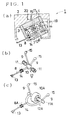
- Fig. 1(a) is a longitudinal sectional view showing an example of a cartridge of the present invention.
- Fig. 1(b) is an enlarged perspective view showing a supporting method of a cantilever and a damping bar each used in the cartridge shown in Fig. 1(a).
- Fig. 1(c) is an enlarged perspective view showing another supporting method of a cantilever and a damping bar.
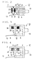
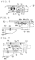
- Figs. 2, 3, 4 and 5 are schematic sectional views showing modified embodiments of separate cartridges.
- Fig. 6 is a schematic sectional view showing an example of a head shell of the present invention.
- Fig. 7 is a schematic sectional view showing an example of an adapter for mounting a cartridge of the present invention.
- Fig. 8(a) is a schematic sectional view showing a further modified cartridge.
- Fig. 8(b) is an enlarged perspective view showing a supporting method of a cantilever and a damping bar used in the cartridge shown in Fig. 8(a).
- Fig. 9 is a schematic sectional view showing a modified example of a head shell.
- Fig. 10 is a schematic sectional view showing the state that a conventional cartridge is mounted to a conventional head shell.
- Fig. 11 is a schematic side view of a record player.
- Basic concept of the present invention is to change at about 90° the operating direction of the upward or downward vibration of the cantilever to cause the operating direction to be directed into a direction extending to or away from the tone arm rotation spindle so as to obtain reaction force to the cantilever vibration from the tone arm rotation spindle, so that the tone arm does not unnecessarily shake upward and downward to thereby stably hold the cartridge.
- the invention similarly changes the operating direction of force from leftward and rightward vibration of the cantilever to cause the same operating direction of that force to be directed into a direction extending to or away from the tone arm rotation arm.
- the cantilever is provided at its root portion with a standing damping bar, an intersection between the cantilever and the damping bar is supported in a manner of being swingably upward, downward, leftward and rightward and an utmost end of the damping bar is sandwiched at its front and rear sides by dampers.
- This feature provides that upward or downward vibration of the utmost end of the cantilever is changed in operating direction about 90° to provide forward or backward vibration of the utmost end of the damping bar, so that reaction force to vibrations of the cantilever can be obtained from the tone arm rotation spindle.
- the supporting portion for the damping bar is subjected only to rotational force but substantially not or at any meaningless values to upward, downward, leftward or rightward force, so that the supporting portion does substantially not transmit force to move up or down the tone arm.
- Leftward or rightward vibration of the cantilever is similarly received by the tone arm rotation spindle.
- the upward and downward direction means a perpendicular direction to a record player when placed horizontally and the leftward or rightward direction and forward or backward direction are set by viewing the cartridge from the tone arm rotation spindle. Also, the forward or backward direction of the cartridge in the case that the damping bar is sandwiched at its forward and backward sides is set with respect to an extending direction of the cantilever as the root portion thereof being at the front side and the stylus tip at the back side.
- the forward or backward direction of the cartridge generally corresponds to that viewed from the tone arm rotation spindle.
- the vibrating direction of the damping bar slightly shifts from the direction extending to the tone arm rotation spindle.
- the slight shift may be negligible, or that cartridge may be slightly shifted in position in mounting to those tone arms to allow vibrating direction of the damping bar to correspond to the direction extending to the tone arm rotation spindle.
- Means for supporting the cantilever and damping bar freely swingably may employ such supporting means as a ball joint or a gyro member that does not move in position but is freely shiftable in direction.
- a ball bearing may be used as the supporting means depending on specific usages.
- the damping bar may be provided on the cartridge body (other than the cantilever) as standing directly from the cartridge body or through other parts.
- an adapter interposed between a head shell and a cartridge or the head shell itself serves to work for the function of changing the operating direction of the vibrations.
- a cartridge may use a general one.
- the cartridge and the head shell may use conventional ones.
- the dampers may use elastic members, such as rubber, plastic or the like customarily employed. Also, such feature may be employed that the damping bar has at utmost end a magnet fixed thereto and additional magnets having the same polarity are arranged facing the front and back sides of that magnet, thereby using repulsive force of the magnets as the damper.
- the damper or the magnets may be provided with a position adjuster comprising a screw or the like to enable adjustment of vibrations of the cantilever.
- the damping bar may be single or use two damping bars standing in a V-like shape.
- Stereophonic recording is the main current today and sound grooves of the records are cut slantwise leftward and rightward at 45° with respect to the perpendicular direction, so that when two damping bars are provided slantwise at 45° with respect to perpendicular direction, each damping bar makes damping following vibrations of the cantilever according precisely to the left and right wave shapes of the sound groove, thereby providing a complete stereophonic sound.
- two or four damping bars may be provided in a X-like shape to cause each damping bar to be damped. Use of a single damping bar may fully control the leftward or rightward vibration but has less efficiency in comparison with the case of two damping bars.
- a spring serving also as a damper may be substituted for the damping bar.
- upper end of the spring is fixed directly to the cartridge body to be directed toward the tone arm rotation spindle so as to transmit vibrations of the cantilever thereto. This feature provides a similar effect to the case using a pipe-like shaped damping bar.
- the cantilever is provided at its root portion with a damping bar which stands thereat, is spherical at its utmost end and is supported at and near the connecting part between the cantilever and the damping bar to a cartridge body by use of an elastic supporting member.
- a hard cup-like shaped stopper having a recess slightly larger in size than the damping bar's spherical end is fixed to the cartridge body, and the spherical end of the damping bar extending almost perpendicularly is received in, contacted with and held by the recess of the cup-like shaped stopper.
- This feature does, similarly with the foregoing features, provide that vibrations of the cantilever are converted into vibrations of the damping bar in a direction extending to or away from the tone arm rotation spindle, so that the spherical utmost end of the damping bar is controlled by the recess of the cup-like shaped stopper to cause vibrations of the damping bar to be transmitted to the tone arm rotation spindle, thereby receiving reaction force therefrom.
- This feature is different from the aforesaid feature in that the supporting part for the damping bar uses an elastic member for absorbing any force (other than rotational force) to be applied to the supporting part due to the feature that clearance between the spherical end of damping bar and the recess of the cup-like shaped stopper is small and the stopper is made of a hard material, such as metal or the like.
- the present invention is not directed to a problem of a larger irregularity on the record surface due to its bending or the like.
- the tone arm is, as conventionally, moved up and down following such irregularity on the record surface to make arrangement thereagainst.
- the stylus tip at the end of the cantilever stably traces the sound groove and is substantially not subjected to unnecessary reaction force or the like from the tone arm itself.
- the damping mechanism for cantilever according to the present invention may be applicable to every cartridge in MC, MM and MI types, condenser type, photo-electric type or the like used conventionally.
- a heavier tone arm which gives a larger moment of inertia to a certain extent provides a preferable result.
- the cartridge according to the present invention is, as aforesaid, not subjected to reaction force from the tone arm itself due to the force of inertia thereof but is firmly held by the tone arm, and the stylus tip traces the sound groove of records as if it sticks fast thereto, so that the phonic information can be reproduced faithfully.
- the reproduced sounds have a larger dynamic range and are clean-cut as those of CDs while being fine, deep and clear as inherently.
- high-pitched tones can be clearly reproduced to sharply provide powerful, vivid, stereophonic and warm sounds.
- the tracking error angle is near zero, the reproduced sounds are very much stereophonic to cause the listener to have an illusion as if he is actually at a concert.
- the cartridge of the present invention does not fully exhibit its ability when an amplifier, a speaker and a record player themselves are poor in efficiency. But, the quality of reproduced sounds is further improved by the cartridge of the present invention but not the conventional cartridge when they are applied to the same reproducing device.
- Fig. 1(a) is a longitudinal sectional view showing an example of a cartridge according to the present invention
- Fig. 1(b) a perspective view showing a cantilever and a damping bar used in the cartridge shown in Fig. 1(a).
- the cartridge 1 is MC type improved based on the orthophone style shown in Fig. 10 and comprises, as that of Fig. 10, a casing 2 serving as a body in which a front yoke 3 and a rear yoke 4 sandwiches a magnet 5, the rear yoke 4 having at its lower end a pole piece 6 fixed thereto and extending forward and slightly downward.
- the pole piece 6 has a groove 7 wherein a cantilever 8 and a damping bar 9 are supported.
- the front yoke 3, rear yoke 4, pole piece 6 and magnet 5 form a loop of magnetic line of force, and magnetic field is generated between the lower end of the front yoke 3 and the utmost end of the pole piece 6.
- the cantilever 8 is made of a pipe or a rod and has at its root portion a spherical member 10 as shown in Fig. 1(b).
- Two damping bars 9 are provided at the top of the spherical member 10 to stand in a V-like shape and substantially perpendicularly to the cantilever 8.
- the angle of the V-like shape is about 90° corresponding to sound groove of records.
- the spherical member 10 is supported at its both sides by two ball holders 11 fixed in the groove 7 to constitute a rotation supporting part 12 in a ball-joint-like formation, so that the cantilever 8 is supported to the pole piece 6 in a manner of being freely swingable upward, downward, leftward and rightward.
- the upright damping bars 9 may be provided directly on a portion of the cantilever 8 which portion is placed forward or backward of the spherical member 10.
- a stylus tip 13 is fixed at the utmost end of the cantilever 8, and a coil 14 for generating electrical energy is mounted on the cantilever 8 at the point near the utmost end of the pole piece 6.
- the damping bar 9 is bent at its utmost end to extend perpendicularly and have a disc-like shaped damper-contact part 15.
- the damper-contact part 15 is sandwiched at its front and rear sides by dampers 17 and 18 placed in a damper accommodating part 16 fixed on the upper side of the pole piece 6. Lead wires are connected between the coil 14 and four terminal pins 19 (two pins are shown in Fig. 1), and the casing 2 has at the upper part a thread bore 20 for fixing the casing to a head shell.
- vibrations of the stylus tip 13 is transmitted to the damping bars 9 through the cantilever 8 to cause the damper-contact parts 15 at the utmost end of damping bars to vibrate in a direction extending to or away from the spindle 114 for rotation of the tone arm 111.
- the damper-contact part 15 at the end of damping bar shifts forward, so that the damper-contact part 15 presses the damper 17 to be subjected to buffer action of the damper 17 and return to the original position, thereby giving a downward force to the stylus tip 13.
- the force pressing the damper 17 is transmitted to the spindle 114 through the tone arm 111 and returns as reaction force F3 from the spindle 114.
- the rotation supporting part 12 does merely change the operating direction of the applied force and does substantially not function upward, so that an upward force is not exerted on the head shell 112 and there causes almost no reaction force from the head shell 112 to the cantilever 8.
- the spindle 114 for rotation of the tone arm firmly stands on the record player 113, so that the cantilever 8 does not vibrate due to reaction force from the spindle 114, whereby the head shell 112 does not vibrate unnecessarily to allow voice current from the coil 14 to be based only on vibration of the cantilever 8, thereby providing reproduced sounds of quite high quality.
- the dampers 17, 18 are subjected to the force only in the direction that they are pressed not as in the conventional cartridge 101, thereby stably providing the buffer action.
- Construction of the rotation supporting part 12 is not limited to those shown and may alternatively use a gyro member in place of the spherical member 10 and the ball holders 11, or use a ball bearing 10A and a shaft member 11A.
- a Y-like shaped cantilever 8A and two damping bars 9 are fixed to a shaft member 11A inserted into and fixed to an inner race of a ball bearing 10A, and an outer race of the ball bearing 10A is mounted and fixed to the pole piece 6.
- the cantilever 8A and damping bars 9A can readily vibrate also leftward and rightward or laterally due to play between the inner and outer races of the ball bearing 10A.
- Fig. 2 shows an example of a cartridge of MM type.
- the cartridge 21 comprises a casing 2 having a frame member 22 which is fixed to the inner surface of the upper part of the casing 2, extends downward and mounts two sets of coils 23.
- a small magnet 24 is fixed at the substantial middle point of the cantilever 8 to be adapted to be moved in and out from the shown gap of the frame member 22.
- the magnet 24 which is smaller and lighter than the coil 14 has such an advantage that the cantilever 8 is subjected to less load.
- the cartridge is different from the cartridge 1 of the above example in that dampers 17, 18 are each fixed to the utmost ends of screws 25, 26 respectively, the bolt 25 being supported to the casing 2 and the bolt 26 to a support 27 projecting on the inner surface of the casing 2, each bolt being adjustable longitudinally.
- This example has the same structure of pole piece 6, rotation supporting part 12 and others as those of the first example and similarly provides reproduced sounds of improved quality.
- Fig. 3 shows a cartridge 31 which is a modified MM type and different from those examples in the construction of damper portions and the generator mechanism.
- a magnet 32 is fixed to the utmost end of a damping bar 9 and magnets 33, 34 of the same magnetic pole are spaced at predetermined intervals from the front and rear sides of the magnet 32, thereby using repulsive force of the magnets as a damper.
- the magnets 33, 34 serve as the dampers 17, 18 of the above examples. Since there is no contact between the magnets and the damping bar 9, vibration of the damping bar 9 is a quite natural one not as in the case wherein the damping bar is arranged to contact with the dampers 17, 18.
- the magnets 33, 34 are fixed to the upper inner surface of the casing 2 through supports 35, 36 in a manner of being adjustable in positions.
- Coils 37, 38 are arranged to house therein the magnets 33, 34, so that when the magnet 32 vibrates, voice current is generated at the coils 37, 38.
- a cartridge 41 shown in Fig. 4 is a kind of combination of the cartridge 21 (Fig. 2) and that 31 (Fig. 3) to be MI type.
- a magnet 42 is fixed to the utmost end of a damping bar 9 and sandwiched at the front and rear sides by dampers 17, 18 made of an elastic member.
- Magnetic members 43, 44, such as iron bars mounting the dampers 17, 18 are interposed between generator coils 45 and 46.
- Reference numerals 47 and 48 denote supports which project in the casing 2 for supporting the magnetic members 43, 44 and coils 45, 46.
- Fig. 5 shows an example of a cartridge 51 using a damping spring 52 in place of the damping bars 9.
- the generator mechanism is MM type as in the cartridge 21 (Fig. 2) and may employ other types.
- two short rods 53 in place of the damping bars 9 are provided as standing on the top of a spherical member 10 and the damping springs 52 are retained at their root portions to the rods 53.
- Remote ends of the damping springs 52 are retained, as directed forward, to a support 54 projecting on the upper inner surface of the casing 2.
- the damping springs 52 serve also as dampers 17, 18 to eliminate the same.
- the cartridges referred to in the above examples are embodiments of the damping method according to the present invention.
- a cartridge according to the present invention should not be limited to those.
- the foregoing cartridges are separately formed from the tone arm to thereby be replaceable but may be integrally formed with the tone arm.
- the damping method according to the present invention can be embodied not only in the cartridges but also in a head shell or the like.
- Fig. 6 shows an example of a head shell provided with a damping mechanism for cantilever and mounting a general cartridge.
- a casing 62 has at the lower part a plate 62a fixed thereto, and a root portion of a member 63 for mounting a cartridge is supported at the remote end of the plate 62a in a manner of being freely swingably upward, downward, leftward and rightward.
- a thicker rod or the like may be used in place of the plate 62a.
- a rotation supporting part 64 may be similar in construction, for example, with the rotation supporting part 12, 12A for cartridges as shown in Figs. 1(b) and 1(c).
- a damping bar 65 is provided as standing on the root portion of the cartridge mounting member 63 and sandwiched at the front and rear sides of the utmost end by dampers 66a, 66b mounted on the head shell body.
- Reference numerals 67a and 67b denote screws for tightly holding the dampers and 68a, 68b supports for supporting the screws.
- the shown head shell 61 is a universal type to be used in a record player wherein head shells are replaceable.
- the head shell structure may be applicable to a head shell integrally formed with a tone arm.
- most of the conventional cartridges in replacement type may be applied to the head shell 61 by use of a screw 69 or other means.
- a modified adapter may be interposed between a conventional head shell 112 and cartridge 101 in order to obtain the effect of improvement of quality of reproduced sounds as in the present invention.
- Fig. 7 shows an example of the feature wherein an adapter 71 having a damping mechanism for a cantilever is mounted to a general head shell and mounts a general cantilever 8.
- a casing 72 has at the lower part a plate 72a fixed thereto, and a root portion of a member 73 for mounting a cartridge is supported at the remote end of the plate 72a in a manner of being freely swingably upward, downward, leftward and rightward.
- a rotation supporting part 74 may be similar in construction, for example, with the rotation supporting part 12, 12A for cartridges as shown in Figs. 1(b) and 1(c).
- a damping bar 75 is provided as standing on the root portion of the cartridge mounting member 73 and sandwiched at the front and rear sides of the utmost end by dampers 76a, 76b mounted on the head shell body.
- Reference numerals 77a and 77b denote screws for tightly holding the dampers and 78a, 78b supports for supporting the screws, 79 a screw for fixing the adapter 71 to the head shell 112 and 80 a screw for fixing a cartridge 101 to the adapter 71.
- the cartridge mounting adapter 71 may be applicable to most of tone arms in cartridge replacement type and economically usable in association with a conventional record player and cartridge in hand.
- a cartridge 81 shown in Fig. 8(a) has MM type of generator mechanism as of the cartridge 21 (Fig. 2) but is different therefrom in the damping mechanism.
- the cantilever 8 is, as shown in Fig. 8(b), provided at its root portion with a single damping bar 82 which is fixed thereat, stands substantially perpendicularly and is supported and fixed at and near the connecting portion between the cantilever and the damping bar to the pole piece 6 by use of an elastic support means 83 having cushioning efficiency.
- the supporting of this connecting portion to the pole piece 6 constitutes a kind of loose rotation-supporting part 84 wherein the connecting portion can shift upward, downward, leftward, rightward, forward and backward.
- the damping bar 82 has a spherical member 85 at its remote end.
- a hard cup-like shaped stopper 87 which has a recess 86 slightly larger in size than the spherical member 85 is fixed to a casing 2.
- the spherical member 85 of the damping bar 82 is contacted with and held by the recess 86 of the stopper 87.
- the spherical member 85 vibrates forward, backward, leftward or rightward with respect to the direction extending to or away from the tone arm spindle.
- the vibration of the spherical member 85 is controlled by the recess 86 of the cup-like shaped stopper 87 to be transmitted to the tone arm spindle, thereby receiving reaction force therefrom, so that the head shell 112 is prevented from vibrating similarly in the foregoing examples and the effect of improvement of quality of reproduced sounds can be obtained.
- the spherical member 85 and the recess 86 and the cup-like shaped stopper 87 is made of a hard member.
- the rotation supporting part 84 is subjected to any force other than rotational force.
- the support means 83 is made of an elastic member.
- the utmost end of the damping bar 82 is not limited to be the spherical member 85 but may have a spherical surface at the top of the damping bar. Also, it is preferable to use metal, hard plastic or the like for the cup-like shaped stopper 87.
- a head shell 91 shown in Fig. 9 adopts the similar structure of rotation supporting part 84 with the cartridge 81 of Example 8.
- a casing 92 has at the lower part a plate 92a fixed thereto, and a root portion of a member 93 for mounting a cartridge is supported at the remote end of the plate 92a in a manner of being freely swingably upward, downward, leftward and rightward.
- the cantilever mounting member 93 is provided at its root portion with a damping bar 95 which is fixed thereat, has a spherical surface 94 at utmost end, stands substantially perpendicularly and is supported and fixed at and near the connecting portion between the cartridge mounting member and the damping bar to the casing 92 by use of an elastic support means 96.
- a hard cup-like shaped stopper 98 which has a recess 97 slightly larger in size than the spherical surface 94 of the damping bar is fixed to the casing 92.
- the spherical surface 94 at the utmost end of damping bar is contacted with and held by the recess 97 of the stopper 98.
- the vibration of the spherical surface portion is controlled by the recess 97 of the cup-like shaped stopper 98 to be transmitted to the tone arm spindle, thereby receiving reaction force therefrom, so that the head shell 112 is prevented from vibrating similarly in the foregoing examples and the effect of improvement of quality of reproduced sounds can be obtained.
- the cantilever damping mechanism may be incorporated with the adapter shown in Fig. 7 to obtain the same effect as above.
- the cantilever damping method according to the present invention changes through the damping bar the cantilever's upward, downward, leftward, rightward and slantwise vibrations upon reproduction of recorded sounds to modified vibrations having vibration component directed to a direction extending to or away from the tone arm spindle, and causes the modified vibrations to be damped forward or rearward in that direction, so that reaction force from the tone arm spindle is applied in that direction to the cantilever, in turn, the stylus tip.
- cartridge and head shell according to the present invention is an incarnation of the cantilever damping method according to the invention and have the following characteristics.
Landscapes
- Physics & Mathematics (AREA)
- Engineering & Computer Science (AREA)
- Acoustics & Sound (AREA)
- Signal Processing (AREA)
- Moving Of Heads (AREA)
Priority Applications (1)
| Application Number | Priority Date | Filing Date | Title |
|---|---|---|---|
| EP92102244A EP0555497A1 (fr) | 1992-02-11 | 1992-02-11 | Amortisseur pour bras portant à cantilever et tête de lecture |
Applications Claiming Priority (1)
| Application Number | Priority Date | Filing Date | Title |
|---|---|---|---|
| EP92102244A EP0555497A1 (fr) | 1992-02-11 | 1992-02-11 | Amortisseur pour bras portant à cantilever et tête de lecture |
Publications (1)
| Publication Number | Publication Date |
|---|---|
| EP0555497A1 true EP0555497A1 (fr) | 1993-08-18 |
Family
ID=8209318
Family Applications (1)
| Application Number | Title | Priority Date | Filing Date |
|---|---|---|---|
| EP92102244A Withdrawn EP0555497A1 (fr) | 1992-02-11 | 1992-02-11 | Amortisseur pour bras portant à cantilever et tête de lecture |
Country Status (1)
| Country | Link |
|---|---|
| EP (1) | EP0555497A1 (fr) |
Cited By (3)
| Publication number | Priority date | Publication date | Assignee | Title |
|---|---|---|---|---|
| EP3086571A1 (fr) * | 2015-04-21 | 2016-10-26 | Kabushiki Kaisha Audio-Technica | Cartouche de capture de type aimant mobile |
| US20180286435A1 (en) * | 2015-09-30 | 2018-10-04 | Dong-Chan SON | Headshell and tonearm for mounting cartridge of audio turntable and audio turntable comprising same |
| CN118474588A (zh) * | 2024-05-25 | 2024-08-09 | 深圳市航声电子科技有限公司 | 一种车载音响及其抗震组件 |
Citations (4)
| Publication number | Priority date | Publication date | Assignee | Title |
|---|---|---|---|---|
| US3142729A (en) * | 1957-12-10 | 1964-07-28 | Litton Systems Inc | Phonograph reproducer |
| FR2069957A1 (fr) * | 1968-06-14 | 1971-09-10 | Electroacustic Gmbh | |
| US3956598A (en) * | 1973-12-22 | 1976-05-11 | Sony Corporation | Moving coil pickup cartridge with diaphragm coupling |
| FR2525060A1 (fr) * | 1982-04-08 | 1983-10-14 | Rca Corp | Dispositif de maintien d'une aiguille de lecture de signaux de disques video |
-
1992
- 1992-02-11 EP EP92102244A patent/EP0555497A1/fr not_active Withdrawn
Patent Citations (4)
| Publication number | Priority date | Publication date | Assignee | Title |
|---|---|---|---|---|
| US3142729A (en) * | 1957-12-10 | 1964-07-28 | Litton Systems Inc | Phonograph reproducer |
| FR2069957A1 (fr) * | 1968-06-14 | 1971-09-10 | Electroacustic Gmbh | |
| US3956598A (en) * | 1973-12-22 | 1976-05-11 | Sony Corporation | Moving coil pickup cartridge with diaphragm coupling |
| FR2525060A1 (fr) * | 1982-04-08 | 1983-10-14 | Rca Corp | Dispositif de maintien d'une aiguille de lecture de signaux de disques video |
Cited By (5)
| Publication number | Priority date | Publication date | Assignee | Title |
|---|---|---|---|---|
| EP3086571A1 (fr) * | 2015-04-21 | 2016-10-26 | Kabushiki Kaisha Audio-Technica | Cartouche de capture de type aimant mobile |
| CN106067718A (zh) * | 2015-04-21 | 2016-11-02 | 铁三角有限公司 | 可动磁铁式拾音头 |
| US9659580B2 (en) | 2015-04-21 | 2017-05-23 | Kabushiki Kaisha Audio-Technica | Moving-magnet type pickup cartridge |
| US20180286435A1 (en) * | 2015-09-30 | 2018-10-04 | Dong-Chan SON | Headshell and tonearm for mounting cartridge of audio turntable and audio turntable comprising same |
| CN118474588A (zh) * | 2024-05-25 | 2024-08-09 | 深圳市航声电子科技有限公司 | 一种车载音响及其抗震组件 |
Similar Documents
| Publication | Publication Date | Title |
|---|---|---|
| KR100324217B1 (ko) | 진동을 갖는 동적인 음성을 제공하는 헤드폰 장치 및 그방법 | |
| US10405076B2 (en) | Elimination of parasitic audio vibrations using spring mounted speakers | |
| US4194744A (en) | Phonograph pick-up transducer using a one-piece bearing and inertial damper fabricated from different materials | |
| US4220341A (en) | Pickup | |
| US10090006B2 (en) | Electromechanical system and method of actuating a stylus | |
| JP3321792B2 (ja) | プレーヤ装置 | |
| US4376304A (en) | Moving coil type stereophonic pickup cartridge | |
| JPH06195601A (ja) | カンチレバーの制動方法及びカートリッジ | |
| US1760647A (en) | Electrical pick-up | |
| US2586362A (en) | Dual point phonograph pickup stylus | |
| US1996511A (en) | Phonograph reproducing system | |
| US2238863A (en) | Translation device for phonographs | |
| US2213936A (en) | Electrodynamic pickup | |
| US2624584A (en) | Phonograph | |
| US4310917A (en) | Pick-up | |
| US6185179B1 (en) | Apparatus and method for recording and playing back sound | |
| US3286043A (en) | Phonograph recorder-reproducer cartridge utilizing supersonic and audio frequency inputs | |
| Frederick | Vertical sound records: Recent fundamental advances in mechanical records on wax | |
| US2182138A (en) | Electric phonograph pickup | |
| CN213366134U (zh) | 一种具有蓝牙传输功能的留声机 | |
| US397280A (en) | Phonograph recorder and reproducer | |
| JP2020087484A (ja) | ヘッドシェル及びその製造方法 | |
| JPS6319104Y2 (fr) | ||
| JPH04132052A (ja) | 磁気ディスク装置 | |
| JPS6076039A (ja) | 対物レンズ駆動装置 |
Legal Events
| Date | Code | Title | Description |
|---|---|---|---|
| PUAI | Public reference made under article 153(3) epc to a published international application that has entered the european phase |
Free format text: ORIGINAL CODE: 0009012 |
|
| AK | Designated contracting states |
Kind code of ref document: A1 Designated state(s): CH DE DK FR GB IT LI NL |
|
| STAA | Information on the status of an ep patent application or granted ep patent |
Free format text: STATUS: THE APPLICATION IS DEEMED TO BE WITHDRAWN |
|
| 18D | Application deemed to be withdrawn |
Effective date: 19940830 |