EP0555536A1 - Lampe submersible pour un réacteur photochimique - Google Patents
Lampe submersible pour un réacteur photochimique Download PDFInfo
- Publication number
- EP0555536A1 EP0555536A1 EP92120051A EP92120051A EP0555536A1 EP 0555536 A1 EP0555536 A1 EP 0555536A1 EP 92120051 A EP92120051 A EP 92120051A EP 92120051 A EP92120051 A EP 92120051A EP 0555536 A1 EP0555536 A1 EP 0555536A1
- Authority
- EP
- European Patent Office
- Prior art keywords
- lamp according
- guide rod
- diving
- outer bulb
- connection
- Prior art date
- Legal status (The legal status is an assumption and is not a legal conclusion. Google has not performed a legal analysis and makes no representation as to the accuracy of the status listed.)
- Granted
Links
Images

Classifications
-
- B—PERFORMING OPERATIONS; TRANSPORTING
- B01—PHYSICAL OR CHEMICAL PROCESSES OR APPARATUS IN GENERAL
- B01J—CHEMICAL OR PHYSICAL PROCESSES, e.g. CATALYSIS OR COLLOID CHEMISTRY; THEIR RELEVANT APPARATUS
- B01J19/00—Chemical, physical or physico-chemical processes in general; Their relevant apparatus
- B01J19/08—Processes employing the direct application of electric or wave energy, or particle radiation; Apparatus therefor
- B01J19/12—Processes employing the direct application of electric or wave energy, or particle radiation; Apparatus therefor employing electromagnetic waves
- B01J19/122—Incoherent waves
- B01J19/123—Ultraviolet light
Definitions
- the invention relates to a diving lamp for a photochemical reactor with a discharge lamp, the discharge lamp being inserted in an outer bulb through which inert gas flows and having a lamp bulb with axially opposite, mechanically stable electrical connections, of which at least one connection simultaneously serves as a holder for the lamp bulb and is held and contacted in a version of the outer bulb, the discharge lamp being releasably held and contacted via a further holder at its other end against axial displacement in the outer bulb.
- the Heraeus Original Hanau D 310625 / 2C 9.89 / VN PK brochure from WC Heraeus GmbH contains an immersion lamp based on the body system with a high-pressure mercury lamp on page 13.
- the radiator is fastened in the immersion tube by means of clamps and seals via a radiator bracket with a feed line, the immersion tube in turn being located in a cooling tube with clamps and seals.
- the dip tube is flushed with an inert gas via an inlet nozzle and an outlet nozzle in the top plate.
- the cooling tube offers the possibility of water cooling between the immersion tube and the reaction material.
- the connection of the head plate or immersion lamp head to the immersion tube and the connection of the immersion tube to the cooling tube is made using standard flange connections.
- Exchanging lamp lamps has proven to be problematic in the case of the known diving lamps, since here the ends of the electrical current leads encased with quartz tube have to be disconnected from the connections to the lamp and a new adaptation of the current leads to the discharge tube to be introduced is necessary. In practice, this means that the current power supply lines can no longer be used and must be replaced by new ones.
- the fused connection between the power supply line and the external connections of the radiator electrodes also requires special professional skill.
- the additional introduction of inert gas supply tubes for example in the form of quartz glass tubes, is also necessary.
- An exchange of lamp lamps such as those resulting from the repair or due to changed requirements for power or lamp spectrum, therefore always requires professional skill and a stockpiling of the respective power supply and their insulating quartz jackets.
- the invention has for its object to provide a diving lamp, the discharge lamp is easily replaceable; In addition, different lamp lengths should also be usable. Another object is to reduce the number of components within the immersion lamp bulb.
- Another advantage is that, depending on the liquid to be treated, it is possible to optimize the suitable lamp by simply replacing it with a plug connection.
- the interior of the protective head is divided into two areas which are sealed off from one another, of which a first area is connected to the inert gas supply and a second area is connected to the inert gas discharge; the first area is communicatively connected to the interior of the outer bulb in the area of its closed end via at least one of the two guide rods, ie a gas connection is formed.
- Nitrogen serves as the inert gas.
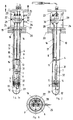
- FIG. 1a shows a longitudinal section of a diving lamp with an inserted lamp, the guide rods extending from the connection area to the end of the outer bulb being recognizable; a shortened representation was chosen by opening in the area of the discharge lamp.
- Figure 1b shows a cross section along the line A B, according to Figure 1a.
- FIG. 2 shows a likewise shortened longitudinal section perpendicular to the plane spanned by the two guide rods reaching to the end of the outer bulb.
- Figure 3 shows a perspective view of the holder and power supply for the discharge lamp, but without a lamp, without the outer bulb surrounding it and without a connection head.
- the discharge lamp 1 with its axially opposite electrical plug connections 2 and 3 is electrically contacted and mechanically by means of a socket 4 and a socket serving as a holder 5 captured.
- the socket 4 is designed as a sliding part, which is arranged displaceably along a first and a second guide rod 6, 7 and is pressed against the electrical connection 2 of the discharge lamp 1 by the pressure of a helical spring 8, which is held centrally by an additional guide rod 16, the other on the other
- the electrical plug connector 3 is electrically contacted and held mechanically by means of the holder 5 designed as a further socket.
- the discharge lamp 1 can be released from engagement with the socket 4 against the pressure of the helical spring 8.
- the holder 5 which is designed as a further holder, is arranged in a fixed manner in the region of the free ends of the two guide rods 6, 7 arranged parallel to one another, the holder being arranged in a stationary manner by means of centering elements 11 extending at the edge and supported against the outer bulb 10. The centering takes place with respect to the longitudinal axis 12 of the outer bulb 10.
- the socket 4 has recesses 13, 14, 15 by means of which it can be displaced parallel to the axis 12 along the guide rod 6, 7 and the additional guide rod 16 carrying the coil spring 8.
- the compression spring is mechanically fixed and electrically conductively fixed on the additional guide rod 16 by means of a fusion connection (welding) 17, a safe distance between the helical spring 8 and the guide rods 6, 7, which are connected to the electrical opposite pole, being ensured.
- the guide rods 6, 7 and 16 are guided through an opening 18 in a plate 19 of the connection area 20 of the connection head 21, the connection head being used for the sealing connection of the photo reactor housing, which is not shown here for the sake of a better overview.
- connection head 21 The interior of the connection head 21 is divided by means of an intermediate plate 22 into an inert gas supply area 23 and an inert gas discharge area 24, the associated gas connections being designated by the reference numbers 25, 26.
- the first and second guide rods 6, 7 are tubular and each open at their upper and lower ends, so that there is a direct gas connection between the inert gas supply area 23 and the end area 27 of the outer bulb 10.
- the return of the inert gas takes place through the opening 18 in plate 19 of the Connection area 20.
- the additional guide rod 16 is also tubular, but one of its ends is closed in order to avoid a gas flow in the opposite direction into the central area of the outer bulb.
- the nitrogen cycle takes place along the flow arrows labeled N2.
- FIG. 1b The area of the cross section along the line A B of FIG. 1a is explained in more detail in FIG. 1b.
- the intermediate plate 22 of the connection head can be seen, wherein the power connections of the first and second guide rods 6, 7 and the additional guide rod 16 can also be seen.
- the intermediate plate 22 is sealed off from the tubular outer wall 28 of the connection head 21 by means of a circumferential seal 29 in the form of a circumferential O-ring 29 lying in a groove 30 in order to avoid mixing the incoming and the outgoing inert gases.
- the eccentric position of the additional guide rod 16 with the applied coil spring 8 can be seen, which has a lateral offset relative to the axis 12 of the outer bulb; In order to avoid an uneven loading of the socket 4, this is guided by its recesses 13, 14, 15 through the guide rods 6, 7, 16 visible in FIG. 1a along the axis 12, only the guide rods 6 and 16 being recognizable in the present figure are.
- the connection bases 31, 32 are inserted in the socket 4 or the holder 5, the base 32 being electrically connected by means of an additional electrical line 33 according to FIG. 1a.
- FIG. 3 the part of the arrangement according to the invention intended for insertion into the outer tube of the diving lamp is explained in more detail before the insertion of a discharge lamp.
- the base 31, 32 of the discharge lamp shown in FIGS. 1 a and 2 provided with pin-shaped connections 2, 3 are, according to FIG. 3, of the sleeve-shaped contact elements 35, 36 of the Version 4 and the bracket 5 added.
- the recesses 13, 14, 15 of the socket 4 can be seen, with the aid of which it can be displaced along the axis 12 in order to easily adapt to different lengths of the radiators to be used.
- the sleeve-shaped contact elements 35, 36 each have hollow cylindrical recesses 37, 38, of which, however, only the recess 37 can be seen here in perspective, while recess 38 can be recognized by the contact element 36 shown partially broken away.
- the helical spring 8 acting as a compression spring is fastened here, as already described above, by means of a welded joint 17 on the guide rod 16 at one end, while the other end of the helical spring 8 is electrically and mechanically connected to the socket 4, with an electrical connection to the sleeve-shaped contact element 35 .
- the holder 5 is attached to the guide rods 6, 7 in an electrically conductive manner on its outer sides by means of clamp-shaped fastening means, the sleeve-shaped contact element 36 likewise being connected to the holder 5 in a mechanically fixed and electrically conductive manner.
- the guide rods 6, 7, 16 are screwed in a gas-tight manner in the intermediate plate 22, the current being supplied via the connecting lines 37, 38, 39 and the connecting lines 37, 38 carrying the same potential.
- the tubular guide rods 6, 7 are each open at their ends, so that the inert gas on the inert gas supply area 23 can flow through the intermediate plate 22 into the end area 27 of the outer bulb, not shown here.
- the return of the inert gas takes place along the axis 12, the socket 4, to the inert gas discharge area 24 located in front of the intermediate plate 22.
- the bases of the discharge lamp with socket-shaped or sleeve-shaped contact elements, in which contact pins engage mechanically detachably, which are firmly connected to the sockets or brackets.
- the plug connections can therefore be realized both by pin-shaped and by socket-shaped bases of the discharge lamp.
- the one base is provided with a pin-shaped contact element (anode side) and the other base is provided with a socket-shaped contact element.
Landscapes
- Chemical & Material Sciences (AREA)
- Physics & Mathematics (AREA)
- Electromagnetism (AREA)
- Health & Medical Sciences (AREA)
- General Health & Medical Sciences (AREA)
- Toxicology (AREA)
- Organic Chemistry (AREA)
- Chemical Kinetics & Catalysis (AREA)
- Vessels And Coating Films For Discharge Lamps (AREA)
- Fastening Of Light Sources Or Lamp Holders (AREA)
Applications Claiming Priority (2)
| Application Number | Priority Date | Filing Date | Title |
|---|---|---|---|
| DE4203840 | 1992-02-10 | ||
| DE4203840A DE4203840C1 (fr) | 1992-02-10 | 1992-02-10 |
Publications (2)
| Publication Number | Publication Date |
|---|---|
| EP0555536A1 true EP0555536A1 (fr) | 1993-08-18 |
| EP0555536B1 EP0555536B1 (fr) | 1995-01-25 |
Family
ID=6451337
Family Applications (1)
| Application Number | Title | Priority Date | Filing Date |
|---|---|---|---|
| EP92120051A Expired - Lifetime EP0555536B1 (fr) | 1992-02-10 | 1992-11-25 | Lampe submersible pour un réacteur photochimique |
Country Status (3)
| Country | Link |
|---|---|
| US (1) | US5334905A (fr) |
| EP (1) | EP0555536B1 (fr) |
| DE (2) | DE4203840C1 (fr) |
Cited By (2)
| Publication number | Priority date | Publication date | Assignee | Title |
|---|---|---|---|---|
| DE19728646A1 (de) * | 1997-07-04 | 1999-01-07 | Heraeus Noblelight Gmbh | Tauchlampe für die Anregung photochemischer Reaktionen |
| EP3279150A1 (fr) * | 2016-08-02 | 2018-02-07 | Peschl Ultraviolet GmbH | Unite d'emetteur comprenant une fixation et un element de tete |
Families Citing this family (10)
| Publication number | Priority date | Publication date | Assignee | Title |
|---|---|---|---|---|
| DE4307884C1 (de) * | 1993-03-12 | 1994-05-11 | Heraeus Noblelight Gmbh | Tauchlampe für einen photochemischen Reaktor und deren Verwendung |
| US5866076A (en) | 1996-12-24 | 1999-02-02 | Steril-Aire U.S.A., Inc. | Single ended germicidal lamp for HVAC systems |
| US6746134B1 (en) * | 2001-07-03 | 2004-06-08 | Field Controls, L.L.C. | UV assembly with switch |
| US6997578B2 (en) * | 2003-05-09 | 2006-02-14 | Steril-Aire, Inc. | Environmentally resistant germicidal system |
| US8742364B2 (en) * | 2010-08-31 | 2014-06-03 | Mag Aerospace Industries, Inc. | Systems and methods for disinfecting water |
| EP2674208A1 (fr) * | 2012-06-17 | 2013-12-18 | UV-Consulting Peschl e. K. | Module d'émetteur UV pour un dispositif d'évacuation d'air, de gaz d'échappement ou d'épuration de l'air ambiant |
| US9932245B2 (en) | 2014-07-23 | 2018-04-03 | Watts Regulator Co. | UV sanitizing assemblies with high dose features and methods for controlling the same |
| US9738547B2 (en) | 2014-07-23 | 2017-08-22 | Watts Regulator Co. | Ultraviolet light sanitizing assembly with flow switch and keyed lamp |
| USD787084S1 (en) * | 2015-04-21 | 2017-05-16 | Watts Water Technologies, Inc. | UV sanitizing lamp |
| US10780377B2 (en) | 2016-11-30 | 2020-09-22 | Watts Regulator Co. | Sanitizing filter system and method for a residential water filtering system |
Citations (3)
| Publication number | Priority date | Publication date | Assignee | Title |
|---|---|---|---|---|
| GB1020934A (en) * | 1963-01-02 | 1966-02-23 | Natural Lighting Corp | Lighting apparatus |
| GB2107110A (en) * | 1981-09-11 | 1983-04-20 | Emi Plc Thorn | Discharge lamps |
| EP0466584A1 (fr) * | 1990-07-09 | 1992-01-15 | Etablissements Perche | Projecteur d'éclairage |
Family Cites Families (9)
| Publication number | Priority date | Publication date | Assignee | Title |
|---|---|---|---|---|
| US2083799A (en) * | 1933-09-25 | 1937-06-15 | Petroleum Rectifying Co California | Method of and apparatus for electrically treating emulsions |
| US2681888A (en) * | 1950-03-22 | 1954-06-22 | Mccraw Laura Peck | Emulsion treating apparatus |
| US2624010A (en) * | 1950-12-01 | 1952-12-30 | Standard Oil Dev Co | Vapor discharge lamp |
| US2963603A (en) * | 1957-05-20 | 1960-12-06 | Edmund H Germer | Discharge device |
| FR2041513A5 (fr) * | 1969-04-28 | 1971-01-29 | Cem Comp Electro Mec | |
| US4179616A (en) * | 1978-02-21 | 1979-12-18 | Thetford Corporation | Apparatus for sanitizing liquids with ultra-violet radiation and ozone |
| US4288846A (en) * | 1979-12-17 | 1981-09-08 | General Electric Company | Floodlight |
| US4963783A (en) * | 1988-12-19 | 1990-10-16 | Gte Products Corporation | Electroded photochemical lamps for photochemical mercury separation |
| JPH0727168B2 (ja) * | 1989-06-21 | 1995-03-29 | 株式会社オーク製作所 | 放電灯の冷却液循環システム |
-
1992
- 1992-02-10 DE DE4203840A patent/DE4203840C1/de not_active Expired - Fee Related
- 1992-11-25 DE DE59201299T patent/DE59201299D1/de not_active Expired - Fee Related
- 1992-11-25 EP EP92120051A patent/EP0555536B1/fr not_active Expired - Lifetime
-
1993
- 1993-02-08 US US08/014,639 patent/US5334905A/en not_active Expired - Fee Related
Patent Citations (3)
| Publication number | Priority date | Publication date | Assignee | Title |
|---|---|---|---|---|
| GB1020934A (en) * | 1963-01-02 | 1966-02-23 | Natural Lighting Corp | Lighting apparatus |
| GB2107110A (en) * | 1981-09-11 | 1983-04-20 | Emi Plc Thorn | Discharge lamps |
| EP0466584A1 (fr) * | 1990-07-09 | 1992-01-15 | Etablissements Perche | Projecteur d'éclairage |
Cited By (3)
| Publication number | Priority date | Publication date | Assignee | Title |
|---|---|---|---|---|
| DE19728646A1 (de) * | 1997-07-04 | 1999-01-07 | Heraeus Noblelight Gmbh | Tauchlampe für die Anregung photochemischer Reaktionen |
| DE19728646C2 (de) * | 1997-07-04 | 2001-10-18 | Heraeus Noblelight Gmbh | Tauchlampe für die Anregung photochemischer Reaktionen |
| EP3279150A1 (fr) * | 2016-08-02 | 2018-02-07 | Peschl Ultraviolet GmbH | Unite d'emetteur comprenant une fixation et un element de tete |
Also Published As
| Publication number | Publication date |
|---|---|
| EP0555536B1 (fr) | 1995-01-25 |
| DE59201299D1 (de) | 1995-03-09 |
| DE4203840C1 (fr) | 1993-06-24 |
| US5334905A (en) | 1994-08-02 |
Similar Documents
| Publication | Publication Date | Title |
|---|---|---|
| EP0555536B1 (fr) | Lampe submersible pour un réacteur photochimique | |
| DE69804192T2 (de) | Hochdruckentladungslampe mit uv-verstärker | |
| DE69132150T2 (de) | Befestigungsvorrichtung | |
| DE2405335C3 (de) | Hochdruckentladungslampe | |
| EP0452743A1 (fr) | Lampe à décharge compacte à basse pression | |
| DE69403176T2 (de) | Elektrische Lampe | |
| DE2215757C3 (de) | Stecker- bzw. Buchsenteil einer Steckvorrichtung für Koaxialkabel | |
| DE3837511A1 (de) | Kraftfahrzeugscheinwerferlampe und verfahren zu ihrer herstellung | |
| DE69007643T2 (de) | Elektrische Lampe. | |
| DE102007061174B4 (de) | Elektrisches Durchführungsmodul und Verfahren zu dessen Herstellung, sowie Druckbehälter- oder Sicherheitsbehälterdurchführung | |
| DE2437774C2 (de) | Verfahren zur Herstellung einer Elektrodeneinführung für eine Hochdruck-Entladungslampe und mittels dieses Verfahrens hergestellte Elektrodeneinführungen | |
| DE3427207C2 (fr) | ||
| EP0321866A2 (fr) | Lampe à d'echarge à haute pression | |
| DE3143432C1 (de) | Elektrodenanordnung fuer einen OEl- oder Gasbrenner | |
| DE19629714C1 (de) | Verfahren zur Herstellung von Anschlußkontakten für Strahler mit Quarzglas-Kolben | |
| DE1815540B2 (de) | Vorrichtung zum bearbeiten von rohrfoermigen werkstuecken mittels druckwellen durch unterwasser-funkenentladung | |
| DE3528587C2 (fr) | ||
| DE3133999C2 (de) | Gasisolierte Kondensator-Durchführung mit Leiterkühlung | |
| DE102014110710A1 (de) | Gasentladungslampenanordnung | |
| DE19904651A1 (de) | Vorrichtung zur Befestigung eines Elektrodenarms an einer Schweißzange | |
| DE29923444U1 (de) | Vorrichtung zur Befestigung eines Elektrodenarms an einer Schweißzange | |
| DE102005031160B4 (de) | Trockenvorrichtung für eine Druckmaschine | |
| EP3279150B1 (fr) | Unite d'emetteur comprenant une fixation et un element de tete | |
| DE10334394B3 (de) | Durchführungsvorrichtung für Laserröhren | |
| DE940663C (de) | Blitzlichtlampe mit schraubenlinienfoermiger Blitzlichtroehre |
Legal Events
| Date | Code | Title | Description |
|---|---|---|---|
| PUAI | Public reference made under article 153(3) epc to a published international application that has entered the european phase |
Free format text: ORIGINAL CODE: 0009012 |
|
| 17P | Request for examination filed |
Effective date: 19921209 |
|
| AK | Designated contracting states |
Kind code of ref document: A1 Designated state(s): CH DE FR GB IT LI |
|
| 17Q | First examination report despatched |
Effective date: 19940224 |
|
| GRAA | (expected) grant |
Free format text: ORIGINAL CODE: 0009210 |
|
| AK | Designated contracting states |
Kind code of ref document: B1 Designated state(s): CH DE FR GB IT LI |
|
| GBT | Gb: translation of ep patent filed (gb section 77(6)(a)/1977) |
Effective date: 19950203 |
|
| REF | Corresponds to: |
Ref document number: 59201299 Country of ref document: DE Date of ref document: 19950309 |
|
| RAP2 | Party data changed (patent owner data changed or rights of a patent transferred) |
Owner name: HERAEUS NOBLELIGHT GMBH |
|
| REG | Reference to a national code |
Ref country code: CH Ref legal event code: PUE Owner name: HERAEUS NOBLELIGHT GMBH |
|
| ET | Fr: translation filed | ||
| ITF | It: translation for a ep patent filed | ||
| PLBE | No opposition filed within time limit |
Free format text: ORIGINAL CODE: 0009261 |
|
| STAA | Information on the status of an ep patent application or granted ep patent |
Free format text: STATUS: NO OPPOSITION FILED WITHIN TIME LIMIT |
|
| 26N | No opposition filed | ||
| PGFP | Annual fee paid to national office [announced via postgrant information from national office to epo] |
Ref country code: DE Payment date: 19971106 Year of fee payment: 6 |
|
| PGFP | Annual fee paid to national office [announced via postgrant information from national office to epo] |
Ref country code: GB Payment date: 19971119 Year of fee payment: 6 |
|
| PGFP | Annual fee paid to national office [announced via postgrant information from national office to epo] |
Ref country code: FR Payment date: 19971128 Year of fee payment: 6 |
|
| PGFP | Annual fee paid to national office [announced via postgrant information from national office to epo] |
Ref country code: CH Payment date: 19980223 Year of fee payment: 6 |
|
| PG25 | Lapsed in a contracting state [announced via postgrant information from national office to epo] |
Ref country code: GB Free format text: LAPSE BECAUSE OF NON-PAYMENT OF DUE FEES Effective date: 19981125 |
|
| PG25 | Lapsed in a contracting state [announced via postgrant information from national office to epo] |
Ref country code: LI Free format text: LAPSE BECAUSE OF NON-PAYMENT OF DUE FEES Effective date: 19981130 Ref country code: CH Free format text: LAPSE BECAUSE OF NON-PAYMENT OF DUE FEES Effective date: 19981130 |
|
| GBPC | Gb: european patent ceased through non-payment of renewal fee |
Effective date: 19981125 |
|
| REG | Reference to a national code |
Ref country code: CH Ref legal event code: PL |
|
| PG25 | Lapsed in a contracting state [announced via postgrant information from national office to epo] |
Ref country code: FR Free format text: LAPSE BECAUSE OF NON-PAYMENT OF DUE FEES Effective date: 19990730 |
|
| REG | Reference to a national code |
Ref country code: FR Ref legal event code: ST |
|
| PG25 | Lapsed in a contracting state [announced via postgrant information from national office to epo] |
Ref country code: DE Free format text: LAPSE BECAUSE OF NON-PAYMENT OF DUE FEES Effective date: 19990901 |
|
| PG25 | Lapsed in a contracting state [announced via postgrant information from national office to epo] |
Ref country code: IT Free format text: LAPSE BECAUSE OF NON-PAYMENT OF DUE FEES;WARNING: LAPSES OF ITALIAN PATENTS WITH EFFECTIVE DATE BEFORE 2007 MAY HAVE OCCURRED AT ANY TIME BEFORE 2007. THE CORRECT EFFECTIVE DATE MAY BE DIFFERENT FROM THE ONE RECORDED. Effective date: 20051125 |