EP0555835A2 - Quantification de code de produit sequentiel pour image colour numérique - Google Patents
Quantification de code de produit sequentiel pour image colour numérique Download PDFInfo
- Publication number
- EP0555835A2 EP0555835A2 EP93102079A EP93102079A EP0555835A2 EP 0555835 A2 EP0555835 A2 EP 0555835A2 EP 93102079 A EP93102079 A EP 93102079A EP 93102079 A EP93102079 A EP 93102079A EP 0555835 A2 EP0555835 A2 EP 0555835A2
- Authority
- EP
- European Patent Office
- Prior art keywords
- color
- chrominance
- luminance
- digital
- histogram
- Prior art date
- Legal status (The legal status is an assumption and is not a legal conclusion. Google has not performed a legal analysis and makes no representation as to the accuracy of the status listed.)
- Withdrawn
Links
- 238000013139 quantization Methods 0.000 title claims abstract description 58
- 239000013598 vector Substances 0.000 claims abstract description 84
- 238000000638 solvent extraction Methods 0.000 claims abstract description 82
- 230000000694 effects Effects 0.000 claims abstract description 60
- 239000000203 mixture Substances 0.000 claims abstract description 58
- 230000000007 visual effect Effects 0.000 claims abstract description 23
- 230000035945 sensitivity Effects 0.000 claims abstract description 9
- 238000000034 method Methods 0.000 claims description 118
- 238000013479 data entry Methods 0.000 claims description 13
- 230000006872 improvement Effects 0.000 claims description 5
- 230000001131 transforming effect Effects 0.000 claims description 5
- 230000008878 coupling Effects 0.000 claims description 3
- 238000010168 coupling process Methods 0.000 claims description 3
- 238000005859 coupling reaction Methods 0.000 claims description 3
- 230000007246 mechanism Effects 0.000 abstract description 24
- 238000005192 partition Methods 0.000 abstract description 8
- 239000003086 colorant Substances 0.000 description 24
- 238000012545 processing Methods 0.000 description 21
- 239000011159 matrix material Substances 0.000 description 20
- 238000010586 diagram Methods 0.000 description 13
- 230000008569 process Effects 0.000 description 13
- 230000009467 reduction Effects 0.000 description 8
- 238000006243 chemical reaction Methods 0.000 description 7
- 238000003384 imaging method Methods 0.000 description 6
- 238000013459 approach Methods 0.000 description 4
- 230000001419 dependent effect Effects 0.000 description 4
- 230000009466 transformation Effects 0.000 description 4
- 230000008901 benefit Effects 0.000 description 3
- 238000013507 mapping Methods 0.000 description 3
- 241000820057 Ithone Species 0.000 description 2
- 230000000593 degrading effect Effects 0.000 description 2
- 238000005516 engineering process Methods 0.000 description 2
- 238000012986 modification Methods 0.000 description 2
- 230000004048 modification Effects 0.000 description 2
- 230000005693 optoelectronics Effects 0.000 description 2
- 230000004044 response Effects 0.000 description 2
- 238000001228 spectrum Methods 0.000 description 2
- 238000012935 Averaging Methods 0.000 description 1
- 208000031481 Pathologic Constriction Diseases 0.000 description 1
- 230000003044 adaptive effect Effects 0.000 description 1
- 238000003491 array Methods 0.000 description 1
- 238000004364 calculation method Methods 0.000 description 1
- 238000004891 communication Methods 0.000 description 1
- 238000007906 compression Methods 0.000 description 1
- 230000006835 compression Effects 0.000 description 1
- 238000013144 data compression Methods 0.000 description 1
- 238000013461 design Methods 0.000 description 1
- 230000006870 function Effects 0.000 description 1
- 238000011160 research Methods 0.000 description 1
Images




Classifications
-
- H—ELECTRICITY
- H04—ELECTRIC COMMUNICATION TECHNIQUE
- H04N—PICTORIAL COMMUNICATION, e.g. TELEVISION
- H04N1/00—Scanning, transmission or reproduction of documents or the like, e.g. facsimile transmission; Details thereof
- H04N1/46—Colour picture communication systems
- H04N1/64—Systems for the transmission or the storage of the colour picture signal; Details therefor, e.g. coding or decoding means therefor
- H04N1/644—Systems for the transmission or the storage of the colour picture signal; Details therefor, e.g. coding or decoding means therefor using a reduced set of representative colours, e.g. each representing a particular range in a colour space
Definitions
- the present invention relates in general to digital color image processing, and is particularly directed to a mechanism for quantizing a digital color image having a relatively high color encoding precision into a 'palette' of color codes that may be stored in a relatively low data resolution color image memory, the contents of which are employed to reproduce an output color image having a high quality that is pleasing to the human visual system.
- color image output devices which are driven by digital color image databases employ an image frame buffer the capacity of which is considerably less than that of the encoding resolution into which an original color image has been digitized by a color opto-electronic imaging device, such as a high precision digitizing color camera.
- a color opto-electronic imaging device such as a high precision digitizing color camera.
- a typical example of this mismatch in data precision is the use of an eight bit frame buffer in association with a color image output device, such as a color display monitor, to store a digital color image having a data precision of twenty-four bits (eight bits per color per pixel).
- the output device e.g. color display
- the output device usually has a resolution of eight bits per color at the input of each of three respective digital-to-analog converters which drive its red, green and blue signal ports
- the limited capacity of the frame buffer means that only 256 out of 16 million possible colors codes are available to define the original digital color image may be stored.
- is effectively transformed into one of a lesser number of output colors (e.g. 28 256 colors) for driving the display.
- Color conversion quantization has been the fundamental technique for reducing the color code resolution of the original color image size to a limited palette of color codes that can be accommodated by the frame buffer and which are selected to as faithfully as possible replicate the color characteristics of the original image.
- Color conversion quantization typically has involved some form of vector quantization and operates to minimize an objective error criterion (usually mean squared error).
- a third class of vector quantization algorithms uses splitting techniques to divide the color space into smaller sub-regions and selects a representative palette color from each sub-region.
- splitting techniques are computationally more efficient than either the iterative or merging techniques and can provide a structure to the color space that enables efficient pixel mapping at the output.
- One of these splitting techniques termed a 'median cut' algorithm, recursively splits a region into two sub-regions by locating a plane perpendicular to the coordinate axis having the greatest range (where the range is the difference between the maximum and minimum values of that coordinate) and which passes through the median point of that coordinate axis.
- a second splitting technique is a variance-based algorithm which splits the region having the largest total squared error (TSE). Data points are projected onto each of the coordinate axes and the projected TSEs computed. The region is then split along that axis yielding the smallest sum of projected TSEs from the two resulting sub-regions.
- TSE total squared error
- a third splitting algorithm which is the most optimal in a quantitative sense, is the binary splitting algorithm.
- the binary splitting algorithm passes a splitting plane through the centroid of all the colors of the region such that the splitting plane is oriented perpendicular to the direction of maximum total squared variation. The latter is derived from the principal eigenvalue and eigenvector of the covariance matrix of the data in that region. At each step the region to be split is that with the largest associated principal eigenvalue.
- the binary splitting algorithm also incorporates spatial activity measures to enhance the subjective quality of the image. For a detailed discussion of the binary splitting algorithm attention may be directed to an article by M. Orchard et al, entitled “Color quantization of images", IEEE Transactions on Signal Processing Vol. 39, No. 12, pp 2677-2690, Dec. 1991.
- the present invention is directed to a reduced computational complexity digital color image quantization mechanism which employs a sequential product code form of vector quantization, to sequentially extract chrominance and luminance values from the vectors and quantize chrominance and luminance features based upon a conditional distribution of these features within partitioned regions of chrominance/luminance color space.
- the present invention is particularly intended to quantize a relatively high data resolution digital color image, such as the twenty-four bit per pixel digitized color image output by a digitizing color camera, into a reduced, practical number or 'palette' of eight bit color codes that are to be stored within the limited capacity memory of the frame buffer associated with an output device for reproducing the original digital color image.
- the palette codes chosen by the sequential product code image quantizing mechanism in accordance with the invention are those that effectively prevent the generation of contouring artifacts in the reproduced image and provide an output image having a quality that is pleasing to the human visual system.
- the sequential product code vector quantization mechanism sequentially partitions a digital image color space (e.g. a luminance, chrominance color space) with respect to its vector coordinate system (e.g. (Y,Cb,Cr) space coordinates) into a plurality of color space sub-regions or color space cells, such that each partitioned color cell is associated with a color of the output palette through which the color composition of a reproduced color image is defined.
- a digital image color space e.g. a luminance, chrominance color space
- vector coordinate system e.g. (Y,Cb,Cr) space coordinates
- histogram in luminance, chrominance (Y, Cb, Cr) color space coordinates) is subdivided into a plurality of parallel slices along a selected first of its color space axes, such as along one of the Cr and Cb chrominance axes.
- This subdivision of the color space is preferably accomplished by performing a sequential binary splitting of an axis, either at a prescribed number of axial splitting locations, or adaptively in dependence upon a performance measure of the results of successive splits, such as a mean squared error criterion.
- a splitting criterion is employed to determine the sequential order of partitioning of the axis.
- the splitting criterion is equal to the product of the number of data values projected upon the segment of the axis to be split and the variance of the data along that segment of the axis.
- the segment of the axis having the largest splitting criterion is split first. After that segment has been split into two sub-segments, respective splitting criteria are then computed for the sub-segments and compared with the splitting criteria for all other segments of the axis. Again, that segment (or sub-segment) of the axes having the largest splitting criterion is split next.
- This process is repeated either until the axis has been partitioned into the number of splits initially assigned to it or, in the case of adaptive partitioning, until or adaptively in dependence upon an 'on-the-fly' performance measure (e.g. mean squared error criterion) of the results of successive splits during the splitting process.
- an 'on-the-fly' performance measure e.g. mean squared error criterion
- the splitting criterion along the luminance axis is scaled or weighted in inverse proportion to the average spatial activity of the region subject to be split.
- a region of lower spatial activity will have a higher weighting value, which is intended to emphasize a region of lower spatial activity, where contouring artifacts are a potential problem.
- each of the chrominance axes Cr and Cb may be split at seven or eight locations, while there may be on the order of 240 splits of the partitioned chrominance regions into luminance-chrominance subregions. This large number of splits along the luminance axis has been found to effectively eliminate objectionable contouring artifacts, thereby resulting in a high quality image that is pleasing to the human visual system.
- each split location along an axis may correspond to the centroid or mean value of the color space population as projected onto the segment of that axis.
- the color space e.g. a luminance, chrominance histogram
- the color space is partitioned by a plane which is perpendicular to the axis and passes through the mean value of the color space population as projected onto that axis.
- chrominance color space chrominance color space (histogram)
- binary splitting of a first chrominance axis produces a set of color space 'slices', each of which is associated with a quantization code value of the selected chrominance coordinate.
- the digital value of the first chrominance coordinate of any pixel of the original digital color image will be quantized to a code value used to identify the slice in which that digital value occurs.
- each of these slices is iteratively split into a plurality of column or strip-shaped luminance-chrominance regions along the second chrominance axis, by performing a binary splitting of the second axis at a number of axial locations, that may be prescribed or determined adaptively, as noted earlier.
- each split location along the second (chrominance) axis preferably corresponds to the centroid or mean value of the color space population of a respective one of the slices resulting from the first split as projected onto the second chrominance axis.
- the strip-shaped luminance-chrominance regions resulting from the second chrominance axis split effectively represent quantization code values associated with the second chrominance component. Namely, the digital value of the second chrominance component of any pixel of the original digital color image will be quantized to a code value used to identify the partitioned luminance-chrominance column in which that digital value occurs.
- chrominance color space For a luminance, chrominance color space (histogram), where the chrominance axes are partitioned first, the resulting column or strip-shaped luminance-chrominance regions are then sequentially partitioned into a plurality of luminance-chrominance sub-regions by performing a binary splitting of the luminance axis.
- Each split location along the luminance axis corresponds to the centroid or mean value of the color space population within the column as projected onto the segment of the luminance axis.
- the color space is partitioned by a plane which is perpendicular to the luminance axis and passes through the mean value of the column of color space population as projected onto the luminance axis.
- Luminance axis partitioning is sequentially repeated until the total number of cells (partitioned luminance-chrominance subregions) corresponds to the desired number of palette colors.
- the luminance-chrominance sub-regions resulting from the luminance axis split effectively represent quantization code values associated with the luminance component. Namely, the digital value of the luminance component of any pixel of the original digital color image will be quantized to a code value used to identify the partitioned luminance-chrominance sub-region in which that digital value occurs.
- the luminance (Y) and chrominance (Cr, Cb) codes are reconverted back into respective R, G and B code values.
- a video memory in which palette color labels are stored may be coupled to a look-up table which generates RGB values associated with the palette color labels.
- the RGB outputs from the look-up table are applied to respective D-A converters associated with the RGB ports of an image output device.
- the present invention resides primarily in what is effectively a prescribed digitized image transformation operator which may, but need not necessarily, be incorporated within the image processing software employed by a digital color image processing system. Consequently, the configuration of such a system and the manner in which it is interfaced with a digital image color source (e.g. a digitizing high precision (e.g. twenty-four bits per pixel) color imagery scanner) and a color image output device (e.g.
- a digital image color source e.g. a digitizing high precision (e.g. twenty-four bits per pixel) color imagery scanner
- a color image output device e.g.
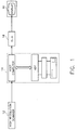
- FIG. 1 diagrammatically illustrates an example of a color image processing system in which the quantization mechanism of the present invention may be employed.
- the exemplary system comprises a high color precision opto-electronic color image digitising scanner 12, the output of which is coupled to a host digitised image processor (host computer) and attendant video display terminal (VDT) 14.
- Scanner 12 contains a sensor pixel array capable of generating output signals which, when converted into digital format, yield a 'digitized' color image file from which high a quality color output image may be obtained.
- This digitally encoded data file, or 'digitized' color image is supplied in the form of an imaging pixel array-representative bit map, resolved to a prescribed code width (e.g. eight bits per color per pixel), to host processor 14.
- a prescribed code width e.g. eight bits per color per pixel
- Host processor 14 contains an image encoding and storage operator, through which each digitized color image file is stored, for retrieval of the digitized images for reproduction on a color image output device, such as an RGB color video display 16.
- a digital-to-analog converter unit 18 is associated with display 16 for driving the respective red, green and blue color guns of the display with analog video signals.
- the capacity of the frame buffer employed with an output device, such as color display 16 may be typically on the order of eight bits per pixel, a code width which is considerably less than the twenty-four bits per pixel into which an original color image has been digitized by scanner 12.
- each of three respective digital-to-analog converters of the digital-to-analog converter unit 18 that drives the RGB ports of display 16 has a resolution of eight bits, it is possible for color display 16 to replicate any of the colors within the original digital color image, as long as a code representative of that particular color is stored in the frame buffer.
- such a color conversion mechanism quantizes a relatively high data precision digital color image, such as the twenty-four bit per pixel digitized color image output by digitizing scanner 12, into a limited number or 'palette' of eight bit color codes that are to be stored within a limited capacity memory of the frame buffer associated with the output device for reproducing the original digital color image.
- the palette codes chosen by the image quantizing mechanism in accordance with the invention are those that effectively minimizes the generation of contouring artifacts in the reproduced image and provide an output image having a quality that is pleasing to the human visual system.
- the colors of the output color code palette are selected by means of a sequential product code vector quantization mechanism which sequentially partitions the color space of a digital color image, such as a chrominance/luminance histogram of the digital color image into a plurality of luminance-chrominance sub-regions or color space cells, such that each partitioned cell is associated with a color of the output palette through which the color composition of a reproduced color image is defined.
- a sequential product code vector quantization mechanism which sequentially partitions the color space of a digital color image, such as a chrominance/luminance histogram of the digital color image into a plurality of luminance-chrominance sub-regions or color space cells, such that each partitioned cell is associated with a color of the output palette through which the color composition of a reproduced color image is defined.
- the color space luminance, chrominance histogram is subdivided into a plurality of parallel slices along a first of the Cr and Cb chrominance axes, by iteratively performing a binary splitting of that axis, typically at a plurality of locations, the number of which may be predetermined or arrived at adaptively, during the splitting process.
- Each axial split location of the selected chrominance axis corresponds to the centroid or mean value of the luminance, chrominance histogram population as projected onto that chrominance axis within the segment of the axis being split.
- the histogram is partitioned by a plane which is perpendicular to that axis and passes through the mean value.
- the luminance-chrominance slices resulting from this first chrominance axis split effectively represent quantization code values associated with the first chrominance component. Namely, the digital value of the first chrominance component of any pixel of the original digital color image will be quantized to a code value used to identify the slice in which that digital value occurs.
- each of these slices is split in an iterative manner into a plurality of column or strip-shaped luminance-chrominance regions along the second chrominance axis, by performing a binary splitting of the second axis.
- Each split location of the second axis corresponds to the centroid or mean value of the histogram population of a respective one of the slices resulting from the previous split as projected onto the second chrominance axis.
- a histogram slice is partitioned by a plane which is perpendicular to the second chrominance axis and passes through the mean value of the slice population as projected onto the second chrominance axis.
- the luminance-chrominance strips resulting from the second chrominance axis split effectively represent quantization code values associated with the second chrominance component. Namely, the digital value of the second chrominance component of any pixel of the original digital color image will be quantized to a code value used to identify the partitioned luminance column in which that digital value occurs.
- the luminance-chrominance regions are then sequentially partitioned into a plurality of luminance-chrominance sub-regions by performing a binary splitting of the luminance axis.
- Each split location along the luminance axis corresponds to the centroid or mean value of the histogram population of a respective one of the luminance-chrominance regions (or a luminance-chrominance sub-region).
- a luminance-chrominance region or sub-region is partitioned by a plane which is perpendicular to the luminance axis and passes through the mean value of the histogram population of that region or sub-region as projected onto the luminance axis.
- the order in which luminance-chrominance regions or sub-regions are partitioned along the luminance axis is influenced by the spatial activity in the luminance-chrominance regions. After each split of a luminance-chrominance region or sub-region, spatial activity variance values are updated (variance values of the two sub-regions of the most recent split are calculated). The next luminance-chrominance region or sub-region split is then based upon which of the luminance-chrominance regions and any luminance-chrominance sub-regions resulting from the most recent split has the largest weighted splitting criterion. This luminance axis partitioning process is sequentially repeated until the total number of histogram cells (partitioned color space (luminance-chrominance) subregions) corresponds to the desired number of palette colors.
- the quantized luminance coordinates of the color space sub-regions resulting from the luminance axis split effectively represent quantization code values associated with the luminance component of the digital color image. Namely, the digital value of the luminance component of any pixel of the original digital color image will be quantized to a code value used to identify the partitioned luminance-chrominance sub-region in which that digital value occurs.
- a respective set of luminance and chrominance (Y,Cr,Cb) output codes is derived from the centroid of each color cell.
- a map of these chrominance and luminance output codes is then generated for the respective pixels of the output color image in accordance with the previously conducted axial splitting or quantization of the chrominance and luminance components of the histogram.
- the resulting map of chrominance and luminance output codes of the output digital color image is then transformed into sets of RGB output color codes for application to the respective RGB digital-to-analog converters that drive color image reproduction device 16.
- a video memory in which palette color labels are stored is coupled to a look-up table which generates RGB values associated with the palette color labels.
- the RGB outputs from the look-up table are applied to respective D-A converters associated with the RGB ports of an image output device.
- the image processing sequence will be illustrated in terms of two dimensions of a luminance, chrominance (Y,Cb,CR) color space, specifically with respect to a single chrominance coordinate (Cr) and the luminance coordinate (Y).
- a digitized color image (sixty-four pixels in the present example) output by scanner 12 of the system of Figure 1 is an RGB image, with each respective color (red, green, blue) encoded to eight bits, for a total of twenty-four bits per pixel. Since the human visual system (HVS) attaches different importance to the luminance (Y) and chrominance (C) attributes of a color stimulus, the original digitized color image that has been encoded in terms of RGB coordinates is transformed into a luminance-chrominance (Y,Cr,Cb) space prior to quantization.
- HVS human visual system
- the luminance-chrominance space employed is preferably related to a gamma-corrected RGB space of the output device 16 by means of a linear transformation customarily employed in color image processing, as described for example in the text by A. Natravali entitled “Digital Pictures,” Plenum Press, 1988.
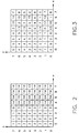
- Figure 2 diagrammatically illustrates an eight-by-eight matrix of encoded chrominance values for the Cr component of the RGB-Y,Cb,Cr transformed image associated with each of the pixels of a sixty-four pixel image array.
- Figure 3 diagrammatically illustrates an eight-by-eight matrix of encoded luminance Y values of the Y,Cb,Cr-transformed image associated with each of the pixels of the array.
- a similar eight-by-eight matrix of encoded chrominance values for the Cb component of the RGB-Y,Cb,Cr transformed image associated with each of the pixels of a sixty-four pixel image array is also formed. However, as noted above, in order to simplify the complexity of the drawings, this additional matrix is not shown.
- each pixel of each eight-by-eight array is resolved to four bits (encompassing sixteen data values 0-15).
- the x and y axes of Figures 2 and 3 are the respective spatial axes of the pixel matrix into which a color image has been digitized.
- the spacial matrices of Figures 2 and 3 are respective chrominance (Cr) and luminance (Y) images derived from a transform of the original RGB image into Y,Cr,Cb color space.
- a second chrominance (Cb) image matrix (not shown) is also obtained from the RGB-Y,Cb,Cr transformation operation.)
- the sequential product code vector quantization mechanism of the present invention employs spatial activity information to control the order of partitioning of the luminance-chrominance regions, that are obtained by sequential partitioning of a Y,Cb,Cr histogram of the image along the Cb and Cr axes.
- the use of spatial activity information to refine the composition of the color code palette achieves a key aspect of the present invention -- minimizing contouring artifacts.
- the color palette includes a sufficient number of variations or shades of a color in a (relatively smooth) region of relatively low spatial frequency, so that a (spatially) large area or region of an image that is essentially the same color, but has HVS-perceptible gradations in tone and shading, will not be reproduced without such gradations, as would be the case if a single given color code were used to reproduce the area of interest, giving rise to a 'cartoon' effect artifact.
- the number of components of the palette can be reduced without degrading the quality of the reproduced image.
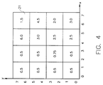
- a matrix of luminance variation values shown in Figure 4 is derived from the luminance matrix of Figure 3.
- the luminance variation matrix of Figure 4 is derived by spatially subdividing the matrix of Figure 3 into a sub-matrix of regions, identified as matrix regions 21 in Figure 4, with each region 21 being associated with a plurality (four in the example shown) of mutually adjacent pixels of the luminance image.
- the variation of the luminance values associated with its associated pixels of Figure 3 is computed.
- the term variation corresponds to the average of the absolute values of the deviation from the mean of each group of luminance values of Figure 3 of a respective region 21 of Figure 4.
- the mean luminance value is 8.0.
- the absolute values of the deviations are (5, 6, 6, 7), yielding an average of 6.0, as specified within the corresponding region of Figure 4.
- the basic mechanism used to derive the color code components of the reproduction color palette comprises a histogram of the luminance (Y) and chrominance (Cr, Cb) representative codes of the digitized image.
- a two-dimensional histogram of the pixel population of the matrices of Figures 2 and 3 is shown in Figure 5, having an abscissa or Cr axis that has been prequantized into in successive pairs of Cr values, and an ordinate or Y axis denoted in successive luminance (Y) values.
- Y luminance
- Y luminance
- the histogram distribution along the Cb axis is prequantized in successive pairs of Cb values.
- the two-dimensional histogram of Figure 5 may be considered to represent the Y,Cb,Cr histogram of an image for which all of the pixels have the same Cb value.
- a first step in the sequential product code vector quantization mechanism of the present invention is the partitioning of the Y,Cb,Cr histogram along one of its chrominance axes, either the Cr axis or the Cb axis by a prescribed number of planes that are perpendicular to that axis and pass through centroids of the segment of the axis being sliced. Thereafter, the other chrominance axis is partitioned, followed by the partitioning of the luminance axis. For purposes of reducing the complexity of the present description, the participation of the Cb coordinate will be temporarily ignored. Suffice it to say that at the beginning of the partitioning process, which of the Cr and Cb chrominance axes is partitioned first is determined in accordance with which coordinate has the largest associated reduction in total squared error for an initial split along that axis.
- D TSE (n1n2/(n1+n2))
- D TSE (n1n2/(n1+n2))
- the value D TSE is determined for each Cr and Cb axis.
- the axis having the larger value of D TSE is partitioned first.
- the number of splits along each respective axis will determine the number of regions or 'cells' into which the histogram color space is subdivided, and thereby determines the number of colors of the palette.
- the total number of available palette codes is 256.
- each of the chrominance axes Cr and Cb of their associated luminance/chrominance histograms may be split at seven or eight locations, while there may be on the order well over 200 splits of the partitioned chrominance regions into luminance-chrominance sub-regions.
- This large number of splits along the luminance axis has been found to effectively eliminate objectionable contouring artifacts, thereby resulting in a high quality image that is pleasing to the human visual system.
- the color palette to be created (the number of cells into which the two dimensional histogram of Figure 5 is to be partitioned) will contain five output color codes, derived from a single split of the Cr axis into a pair of chrominance regions which, in turn, are partitioned along the luminance axis until the histogram has been subdivided into a total of five color cells.
- the Cr axis With a single split of the Cr axis into two chrominance regions, three additional splits along the Y axis are required to partition the two chrominance regions into five luminance-chrominance sub-regions. The centroids of these five sub-regions represent the output color codes of the palette.
- Each of the chrominance axes (Cr, Cb) of the histogram is prequantized into pairs of chrominance values. This prequantization is to take advantage of the fact that the human visual system is less sensitive to chrominance variations than luminance variations, thus making it possible to reduce computational complexity by prequantizing the chrominance data, dropping the least significant bit.
- a color activity diagram shown in Figure 6 is next generated.
- the color activity diagram of Figure 6 is obtained by associating each luminance value of the spatial luminance image of Figure 3 with respective values of the spatial chrominance image of Figure 2 and assigning to the associated chrominance and luminance values one of the variation values of Figure 4.
- the Cr chrominance components of the image of the present example are concentrated in the vicinity of two (extreme) regions of the color space, rather than being spread across the entire color spectrum. This implies that the chrominance components of the color palette will congregate in the vicinity of two regions, one at the lower end of the chrominance axis and one at the upper end of the chrominance axis. (It should be noted that not every image will have its histogram split into only two chrominance regions; typically more regions of concentrated chrominance activity can be expected. The occurrence of two regions at opposite ends of the Cr chrominance axis in the present example is merely for purposes of illustration.)
- the sequential product code vector quantization mechanism of the present invention sequentially partitions the histogram first along the respective chrominance coordinates and then along the luminance coordinate. In particular, for whichever chrominance axis is partitioned first (based upon its larger reduction in total squared error, described above) a prescribed number of partitioning splits is identified.
- the chrominance axes Cr and Cb may be subjected to seven or eight binary splits.
- the histogram will have been partitioned into eight parallel slices along the Cb axis.
- a splitting criterion L is employed to determine the sequential order of partitioning of the axis.
- the splitting criterion L is equal to the product of the number of data values projected upon the segment of the axis to be split and the variance of the data along that segment of the axis.
- the segment of the axis having the largest splitting criterion L is split first. After that segment has been split into two sub-segments, respective splitting criteria are then computed for the sub-segments and compared with the splitting criteria for all other segments of the axis. Again, that segment (or sub-segment) of the axis having the largest splitting criterion is split next. This process is repeated until the axis has been partitioned into the number of splits initially assigned to it.
- FIG. 6A The partitioning of the Cb axis is diagrammatically illustrated in Figure 6A, which shows the projection of seven binary splitting planes Cb1-Cb7 on the Cb-Cr plane, which are perpendicular to the Cb axis and subdivide the histogram into eight parallel slices SCb1 - SCb8.
- the partitioning is a binary operation, the number of partitioned segments or regions is always one more than the number of splits.
- eight slices SCb1- SCb8 result from seven splits Cbs1-CBs7.
- each split of the Cr axis will be associated with a respectively different one of the eight parallel slices SCb1-SCb8 of Figure 6A.
- L the above-reference splitting criterion L.
- slice Scb1 has the largest splitting criterion.
- slice Scb1 will be split at its centroid, shown in Figure 6B as split Crs1, into two sub-slices or regions, one of which is to the left of split Crs1 and one of which is to the right of split Crs1, as viewed in Figure 6B.
- slice SCb3 has the largest splitting criterion.
- slice Scb3 will be split at its centroid, shown in Figure 6B as split Crs3, into two sub-slices or regions, one of which Rcr5 is to the left of split Crs3 and one of which Rcr6 is to the right of split Crs3.
- This process of sequential splitting and updating the splitting criteria continues until the partitioned histogram of Figure 6A has been split along the Cr axis a total of eight splits.
- Figure 6B shows an example of how Figure 6A might be split after eight splits. Note that no splitting of slices Scb2 or Scb6 has occurred, while each of slices Scb1 and Scb5 contains two splits.
- the second chrominance axis split (along coordinate axis Cr) thereby subdivides the histogram into twice as many regions in the Cr-Cb plane as the number of splits along the second (Cr) axis to be partitioned.
- Each of the resulting regions RCr1-RCr16 may be considered a sub-slice or column extending parallel to the Y axis or orthogonal to the plane of Figure 6B.
- These sixteen regions or columns RC1-RC16 are then further partitioned by sequential binary splitting along planes orthogonal to the Y axis, until the color space has been subdivided into a total of 256 luminance-chrominance sub-regions or color cells.
- Splitting the histogram into eight quantized segments or slices SCb1-SCb8 along the first (Cb) axis yields a code width of three bits.
- Subdividing the eight slices of the first axial split into sixteen quantization sub-regions RCr1-RCr16 requires a total code width of four bits, or one additional bit.
- the remaining available slices of the regions RCr1-RCr16 of Figure 6B into 240 luminance sub-regions requires a total of eight bits, or four bits in addition to the four bits associated with the Cb and Cr axial partitioning.
- the color palette to be created is to contain five output color codes.
- the histogram of Figure 5 there will be a single split along the chrominance axis which will create two chrominance regions. These two chrominance regions will then be further partitioned along the luminance axis until a total of five luminance-chrominance sub-regions are realized. The centroids of these five sub-regions represent the output color codes of the palette.
- a simplified or 'compacted' version of the histogram of Figure 4 may be created by projecting onto the Cr axis the sums of the histogram values along the Y axis, thereby producing a 'marginal Cr histogram' shown in Figure 7.
- the chrominance axis is partitioned by a prescribed number of sequential binary splits beginning with the centroid or mean of the marginal Cr histogram, and proceeding through the centroids of the split regions or segments into which the marginal histogram has been partitioned by the split, and so on, until the Cr axis has been partitioned into a plurality of chrominance regions the number of which is one more than the prescribed number of splits.
- a chrominance region partitioning point Crp is that which passes through the mean of the marginal Cr histogram of Figure 7.
- chrominance region map or look up table shown in Figure 9 is derived.
- This chrominance LUT effectively corresponds to the chrominance look up table CrLUT in Figure 6C, referenced previously, and is defined by quantizing the original four bits resolution of the Cr chrominance data (covering chrominance values 0-15) into a single bit (0 or 1).
- the splitting criterion employed to determine the order of partitioning of the palette color space along the luminance axis of the histogram is 'weighted' in accordance with the associated distribution of the color activity, set forth in Figure 6.
- luminance-chrominance region partitioning is governed by which of the regions produces the largest 'weighted' splitting criterion, based upon spatial activities within the regions.
- the normal splitting criterion L is equal to the product of the number of data values projected upon the segment of the axis to be split and the variance of the data along that segment of the axis.
- the segment of the axis having the largest splitting criterion L is split first. After that segment has been split into two sub-segments, respective splitting criteria are then computed for the sub-segments and compared with the splitting criteria for all other segments of the axis. Again, that segment (or sub-segment) of the axis having the largest splitting criterion is split next. This process is repeated until the axis has been partitioned into the number of splits initially assigned to it.
- the sensitivity of the human visual system to contouring artifacts in an image region with low spatial activity is taken into account in order to minimize contouring artifacts.
- the present invention operates to avoid contouring artifacts in the image reproduced from the color palette by including within the color code capacity of the palette a sufficient number of variations or shades of a color for an image region of relatively low spatial frequency.
- a (spatially) large region of an image that is essentially the same color but has HVS-perceptible gradations in tone and shading will not be reproduced without such gradations, as would be the case if a single given color code were used to reproduce the area of interest, giving rise to the previously mentioned 'cartoon' effect.
- the number of color codes can be reduced without degrading the quality of the reproduced image.
- the color activity diagram of Figure 6 is used to generate weighting values wr for scaling the splitting criteria L of each of the regions of interest to modified splitting criteria L'.
- the weighting value wr of each region is calculated to be equal to the reciprocal of the average activity of the region.
- the average activity is computed to be the averaged sum of the products of the number of data values for each respective luminance value within the region and the activity value for that luminance value as listed in Figure 6.
- the averaging is taken over the total number of data values within the region for which the splitting criterion is to be calculated.
- a region of lower spatial activity will have a higher weighting value, which is intended to emphasize a region of lower spatial activity, where contouring artifacts are a potential problem.
- the weighted luminance activity of chrominance region Cr2 is larger than that of chrominance region Cr1, so that splitting along the luminance axis will take place first within chrominance region Cr2.
- the partitioning of chrominance region Cr2 along the Y axis of the histogram is determined by computing the Y axis mean of the histogram data within chrominance region Cr2, tabulated in a conditional luminance histogram YCr2 shown in Figure 8 adjacent to chrominance region Cr2.
- conditional' is used to describe a marginal histogram the color space coverage of which is conditional upon a previous partitioning of the color space.
- marginal histograms YCr1 and Ycr2 respectively associated with regions Cr1 and Cr2 are termed conditional histograms.
- the mean of the conditional luminance histogram YCr2 is calculated between a value of 8.0 and 9.0 and therefore is located at a Y value of 9.0.
- the sequential product code splitting criterion causes chrominance region Cr2 to be partitioned into a luminance-chrominance sub-region YCr2-1 encompassing luminance values 0-8 and a luminance-chrominance sub-region YCr2-2 encompassing luminance values 9-15, as diagrammatically shown in Figure 10.
- respective weighted splitting criteria L' are generated for each of luminance-chrominance sub-regions YCr2-1 and YCr2-2 and are compared with the (previously calculated) weighted splitting criterion L' for chrominance region Cr1 (which has not yet been partitioned along the Y axis), in order to determine which region is to be partitioned next.
- the updating of the weighted splitting criteria reveals that, with chrominance region Cr2 having been partitioned into luminance-chrominance sub-regions YCr2-1 and YCr2-2 because of its very substantial spread, the weighted splitting criteria L' of each of luminance-chrominance sub-regions YCr2-1 and YCr2-1 are calculated to be smaller than that of chrominance region Cr1, so that chrominance region Cr1 is partitioned next.
- the partitioning of a chrominance region along the Y axis of the histogram is determined by computing the Y axis centroid of the histogram data within that region, here using the marginal luminance histogram YCr1 shown in Figure 10 adjacent to chrominance region Cr1.
- the mean of the marginal luminance histogram YCr1 is calculated to occur between a value of 3.0 and 4.0, which causes chrominance region Cr1 to be partitioned into a luminance-chrominance sub-region YCr1-1 encompassing luminance values 0-3 and a luminance-chrominance sub-region YCr1-2 encompassing luminance values 4-15, as shown in Figure 11.
- the histogram has been partitioned into four of the five cells that will make up the color code palette.
- respective weighted splitting criteria are generated for each of luminance-chrominance sub-regions YCr1-1 and YCr1-2 and compared with the (previously calculated) weighted splitting criteria for each of luminance-chrominance sub-regions YCr2-1 and YCr2-2.
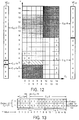
- the weighted splitting criterion of luminance-chrominance sub-region YCr1-1 is the largest of the four, so that luminance-chrominance sub-region YCr1-1 is partitioned into a pair of sub-regions YCr1-1a and YCr1-1b, shown in Figure 12 as encompassing luminance values 0-2 for sub-region YCr1-1a and luminance value 3 for luminance-chrominance sub-region YCr1-1b.
- the sequential product code partitioning of the histogram into the five requisite cells is now complete and is represented by the partitioning of the marginal luminance histograms YCr1 and YCr2 of Figure 12.
- the partitioned marginal luminance histograms YCr1 and YCr2 of Figure 12 are next combined into a luminance look-up table illustrated in Figure 13, with numerical code values 0-4 used to identify with which of respective partitioned luminance-chrominance sub-regions YCr1-1a, YCr1-1b, YCr1-2, YCr2-1 and YCr2-2, matrix locations of the histogram are associated.
- the look-up table of Figure 13 has a one-bit chrominance code to identify one of the chrominance regions Cr1 and Cr2, as denoted by the chrominance region map or look up table shown in Figure 9 and corresponding to look-up table CrLUT in the cascaded configuration of Figure 6C.
- Figure 13 effectively associates a chrominance bit value and a luminance bit value with one of the numerical code values 0-4 that identifies one of the partitioned luminance-chrominance sub-regions YCr1-1a, YCr1-1b, YCr1-2, YCr2-1 and YCr2-2, each of which represents one of the five palette colors.
- the actual chrominance and luminance values used to define each color code of the palette are the Cr and Y coordinates of the centroids of the respective luminance-chrominance sub-regions of the partitioned histogram of Figure 12. These calculated centroid values are tabulated in the palette color map shown Figure 14, which lists each luminance-chrominance sub-region, its associated numerical value employed in the Y look-up table of Figure 13 and the calculated Cr and Y coordinates of the centroids of each sub-region.
- Figure 15 spatially associates each of the pixels of the image array with one of the numerical values (0-4) of the respective luminance-chrominance sub-regions of the histogram, and tabulated in the look-up table of Figure 13.
- a chrominance Cr value and a luminance value Y of the original digital color image are obtained.
- the quantized Cr value of '1' and the luminance value of '2' produce the luminance-luminance sub-region numerical identifier '3'.
- the foregoing example of the sequential product code vector quantization mechanism of the present invention has been described and illustrated for a two-dimensional Y-Cr color space, it is actually carried out for a three-dimensional color space, taking into account the Cb coordinate of the Y,Cr,Cb coordinate system, so that the respective histograms and associated conversion tables of Figures 5-12 are actually associated with a three-dimensional color space.
- the resulting output code map of Figure 14 for the complete three-dimensional color space will also include a listing of output Cb values, in addition to the Y and Cr values currently listed.
- a video memory 31 in which palette color labels are stored may be coupled to a look-up table 33, which generates RGB values associated with the palette color labels.
- the RGB outputs of look-up table 33 are applied to respective D-A converters 35R, 35G and 35B associated with the RGB ports of the image output device 16.
- the processing of three dimensional data may require an extremely large amount of memory (e.g. even with the prequantization of the two chrominance components a 256x128x128 (four megabytes) array)
- histogram entries are generated sequentially in association with quantization processing along each respective coordinate axis.
- marginal and conditional histograms such as the marginal Cr histogram illustrated in Figure 7, and the conditional luminance histograms YCr1 and YCr2 shown in Figures 8, 10 and 11 are generated.
- a single one-dimensional marginal histogram which comprises a summation of all data entries projected upon the respective axis
- quantization of the first axis processed (the Cr axis) requires only a one-dimensional marginal histogram ( Figure 7).
- the sequential processing of the next coordinate also employs one dimensional histogram storage.
- a plurality of one-dimensional histograms are required.
- the number of conditional histograms required for any coordinate axis will depend upon the number of conditional histograms employed to quantize the previous axis and the number of splits of that axis.
- a pair of conditional histograms are generated for the luminance coordinate in association with the two quantized regions YCr1 and YCr2 into which the Cr coordinate has been partitioned based upon the processing of its one dimensional histogram.
- Another data entry-dependent method to reduce histogram memory involves the generation of a two-dimensional array to represent the three-dimensional histogram.
- the three-dimensional color space is stored in terms of two coordinates, e.g. the Cr and Cb chrominance coordinates.
- Each entry of the array is a look-up table of color data covering the range of the luminance values for a respective chrominance coordinate location.
- this array is a compressed version of the three-dimensional histogram, the degree of compression depending upon the number of color space coordinates having no data entries.
- An entry value of a third coordinate, such as luminance may be stored as a binary tree structure. When accessing the two-dimensional array a corresponding value of a third coordinate data entry is located by conducting a binary search along the third coordinate (luminance axis) of the two-dimensional array.
- a significant processing advantage of the present invention is the manner in which the above described quantization look-up tables are effectively cascaded with one another, as shown in Figure 6C, which allows the image data to be read in, pixel by pixel, and thus obviates the need to store the entire image in memory. Moreover, since it is unnecessary to store the entire image in memory in order to perform instantaneous mapping at the output of the process, it is not necessary to use the entire image in order to configure the output color code palette.
- the present invention may also be used with subsampled images.
- the image may be subsampled either vertically (along the y axis), horizontally (along the x axis), or both.
- the samples may be nonuniformly spaced.
- the number of pixels being processed is reduced by a factor of m2; consequently, processing time can be reduced.
- the effect of subsampling in the course of sequential splitting will depend upon the extent to which the subsampling of the image reduces the number of distinct colors. Still, a significant reduction in processing time is afforded with only a minimal reduction in image quality.
- the sequential product code vector quantization technique of the present invention effectively serves as a digital image data compression mechanism that is capable of successfully quantizing chrominance and luminance features of an image based upon a conditional distribution of these features within partitioned regions of chrominance/luminance color space.
- the sequential product code scheme provides a set of coordinate conversion look-up tables which, when cascaded together, provide a transform operator for rapidly converting the color value of each pixel of an original image into an output image color code that both closely matches the color of the original image and is spatial activity dependent, so as to prevent the generation of contouring artifacts in the reproduced image.
- the invention may be summarized as follows:
Landscapes
- Engineering & Computer Science (AREA)
- Multimedia (AREA)
- Signal Processing (AREA)
- Image Processing (AREA)
- Color Television Systems (AREA)
- Facsimile Image Signal Circuits (AREA)
- Controls And Circuits For Display Device (AREA)
Applications Claiming Priority (2)
| Application Number | Priority Date | Filing Date | Title |
|---|---|---|---|
| US07/833,529 US5544284A (en) | 1992-02-11 | 1992-02-11 | Sequential product code quantization of digital color image |
| US833529 | 1992-02-11 |
Publications (2)
| Publication Number | Publication Date |
|---|---|
| EP0555835A2 true EP0555835A2 (fr) | 1993-08-18 |
| EP0555835A3 EP0555835A3 (en) | 1993-10-13 |
Family
ID=25264659
Family Applications (1)
| Application Number | Title | Priority Date | Filing Date |
|---|---|---|---|
| EP19930102079 Withdrawn EP0555835A3 (en) | 1992-02-11 | 1993-02-10 | Sequential product code quantization of digital color image |
Country Status (3)
| Country | Link |
|---|---|
| US (2) | US5544284A (fr) |
| EP (1) | EP0555835A3 (fr) |
| JP (1) | JPH05282435A (fr) |
Cited By (9)
| Publication number | Priority date | Publication date | Assignee | Title |
|---|---|---|---|---|
| EP0680223A1 (fr) * | 1994-04-22 | 1995-11-02 | Winbond Electronics Corporation | Méthode et appareil pour la conversion en espace de couleurs |
| EP1137260A3 (fr) * | 2000-01-26 | 2001-11-21 | Lucent Technologies Inc. | Procédé de quatification en couleurs dans des images couleur |
| WO2002023889A3 (fr) * | 2000-09-06 | 2002-06-06 | Koninkl Philips Electronics Nv | Transfert de donnees entre des espaces de couleur rvb et ycrcb pour une interface dct |
| EP1274227A3 (fr) * | 2001-07-06 | 2007-08-15 | Eastman Kodak Company | Méthode de représentation d'une image en couleur utilisant une palette de couleurs |
| EP1274228A3 (fr) * | 2001-07-06 | 2007-08-15 | Eastman Kodak Company | Méthode de représentation d'une image en couleur utilisant une palette de couleurs basée sur des couleurs importantes détectées |
| CN101924949B (zh) * | 2009-06-12 | 2012-06-20 | 华硕电脑股份有限公司 | 影像处理方法与影像处理系统 |
| CN103477621A (zh) * | 2011-01-28 | 2013-12-25 | 艾艾欧有限公司 | 基于hvs模式的颜色转换 |
| US9554142B2 (en) | 2011-01-28 | 2017-01-24 | Eye IO, LLC | Encoding of video stream based on scene type |
| CN114365493A (zh) * | 2019-09-30 | 2022-04-15 | Ati科技无限责任公司 | 应用于调色板表推导的并行直方图计算 |
Families Citing this family (107)
| Publication number | Priority date | Publication date | Assignee | Title |
|---|---|---|---|---|
| US5544284A (en) * | 1992-02-11 | 1996-08-06 | Eastman Kodak Company | Sequential product code quantization of digital color image |
| DE4310727C2 (de) * | 1992-04-06 | 1996-07-11 | Hell Ag Linotype | Verfahren und Einrichtung zur Analyse von Bildvorlagen |
| EP0578950A3 (en) * | 1992-07-15 | 1995-11-22 | Ibm | Method and apparatus for converting floating-point pixel values to byte pixel values by table lookup |
| US6757438B2 (en) * | 2000-02-28 | 2004-06-29 | Next Software, Inc. | Method and apparatus for video compression using microwavelets |
| US5740428A (en) * | 1995-02-07 | 1998-04-14 | Merge Technologies, Inc. | Computer based multimedia medical database management system and user interface |
| US5621465A (en) * | 1995-04-11 | 1997-04-15 | Matsushita Electric Industrial Co., Ltd. | Color image encoder |
| DE19609859C1 (de) * | 1996-03-13 | 1997-07-24 | Siemens Ag | Verfahren zur Bildung einer Bild-Transformationsmatrix für ein beliebig geformtes Bildsegment eines digitalen Bildes, durch einen Rechner |
| KR100204543B1 (ko) * | 1996-07-22 | 1999-06-15 | 윤종용 | 휴/새츄레이션을 이용한 색조정기능을 갖는 디스플레이 장치의 제어방법 |
| US6078688A (en) * | 1996-08-23 | 2000-06-20 | Nec Research Institute, Inc. | Method for image segmentation by minimizing the ratio between the exterior boundary cost and the cost of the enclosed region |
| US6081276A (en) * | 1996-11-14 | 2000-06-27 | International Business Machines Corporation | Method and apparatus for creating a color name dictionary and for querying an image by color name |
| KR100255350B1 (ko) * | 1997-05-27 | 2000-05-01 | 윤종용 | 비디오 신호를 이용한 모니터 제어방법 |
| US5880744A (en) * | 1997-06-27 | 1999-03-09 | Microsoft Corporation | Method and apparatus for vector transformation involving a transformation matrix |
| FR2766644B1 (fr) * | 1997-07-22 | 1999-11-12 | France Telecom | Procede d'estimation de la perception locale des erreurs de quantification chromatiques dans une image fixe |
| US5982992A (en) * | 1997-09-05 | 1999-11-09 | Xerox Corporation | Error diffusion in color printing where an intra-gamut colorant is available |
| AU9676298A (en) * | 1997-10-01 | 1999-04-23 | Island Graphics Corporation | Image comparing system |
| US6268939B1 (en) * | 1998-01-08 | 2001-07-31 | Xerox Corporation | Method and apparatus for correcting luminance and chrominance data in digital color images |
| US6239886B1 (en) * | 1998-01-08 | 2001-05-29 | Xerox Corporation | Method and apparatus for correcting luminance and chrominance data in digital color images |
| US5990864A (en) * | 1998-01-12 | 1999-11-23 | Autodesk, Inc. | Converting color images to an arbitrary palette |
| US6392699B1 (en) | 1998-03-04 | 2002-05-21 | Intel Corporation | Integrated color interpolation and color space conversion algorithm from 8-bit bayer pattern RGB color space to 12-bit YCrCb color space |
| US6356276B1 (en) * | 1998-03-18 | 2002-03-12 | Intel Corporation | Median computation-based integrated color interpolation and color space conversion methodology from 8-bit bayer pattern RGB color space to 12-bit YCrCb color space |
| US6262812B1 (en) * | 1998-04-30 | 2001-07-17 | Xerox Corporation | Method and apparatus for object-oriented adjustment of color attributes in a perceptually uniform manner |
| US9848105B1 (en) * | 1998-05-18 | 2017-12-19 | Xerox Corporation | Reducing smear and slow response artifacts in vector error diffusion |
| US6483606B1 (en) | 1998-08-26 | 2002-11-19 | Xerox Corporation | Error diffusion on moderate numbers of output colors |
| US6256409B1 (en) | 1998-10-19 | 2001-07-03 | Sony Corporation | Method for determining a correlation between images using multi-element image descriptors |
| US6445834B1 (en) | 1998-10-19 | 2002-09-03 | Sony Corporation | Modular image query system |
| US6236406B1 (en) * | 1998-10-21 | 2001-05-22 | Sony Corporation | Three-dimensional color space display |
| US6326977B1 (en) * | 1998-11-03 | 2001-12-04 | Sharp Laboratories Of America, Inc. | Rendering of YCBCR images on an RGS display device |
| JP2000238338A (ja) * | 1999-02-23 | 2000-09-05 | Matsushita Electric Ind Co Ltd | 画像処理装置 |
| US6356672B1 (en) * | 1999-03-08 | 2002-03-12 | Sharp Laboratories Of America, Inc. | Method and apparatus for reducing the color registration artifact of image capture devices |
| US6978042B1 (en) * | 1999-04-23 | 2005-12-20 | The Regents Of The University Of California | Color image segmentation method |
| US6262710B1 (en) * | 1999-05-25 | 2001-07-17 | Intel Corporation | Performing color conversion in extended color polymer displays |
| KR100512118B1 (ko) * | 1999-06-10 | 2005-09-02 | 엘지전자 주식회사 | 칼라스페이스의 최적 양자화 방법 |
| US6535635B1 (en) | 1999-10-25 | 2003-03-18 | Xerox Corporation | Error clipping for vector error diffusion |
| NL1013669C2 (nl) * | 1999-11-25 | 2001-05-28 | Ocu Technologies B V | Werkwijze en inrichting voor kleurkwantisatie. |
| JP2001184521A (ja) * | 1999-12-27 | 2001-07-06 | Mitsubishi Electric Corp | 3次元グラフィックスシステム |
| JP4368513B2 (ja) * | 1999-12-27 | 2009-11-18 | 富士フイルム株式会社 | 画像処理方法および装置並びに記録媒体 |
| AUPQ618500A0 (en) * | 2000-03-13 | 2000-04-06 | Canon Kabushiki Kaisha | Memory management of compressed images data |
| GB2363018B (en) * | 2000-04-07 | 2004-08-18 | Discreet Logic Inc | Processing image data |
| JP2001338284A (ja) * | 2000-05-25 | 2001-12-07 | Matsushita Electric Ind Co Ltd | 画像処理方法、画像処理装置及び画像処理システム |
| WO2002103580A2 (fr) * | 2001-06-15 | 2002-12-27 | Massachusetts Institute Of Technology | Estimation adaptative de moyennes et normalisation de donnees |
| JP2004536731A (ja) * | 2001-07-30 | 2004-12-09 | ジ アックレイ マルティネス カンパニー デイビーエイ エムジーアイ ステューディオ | システム混合を補償するシステムと方法 |
| US7020329B2 (en) * | 2001-08-31 | 2006-03-28 | Massachusetts Institute Of Technology | Color image segmentation in an object recognition system |
| KR100850705B1 (ko) * | 2002-03-09 | 2008-08-06 | 삼성전자주식회사 | 시공간적 복잡도를 고려한 적응적 동영상 부호화 방법 및그 장치 |
| US6873439B2 (en) * | 2002-03-13 | 2005-03-29 | Hewlett-Packard Development Company, L.P. | Variational models for spatially dependent gamut mapping |
| US7889211B2 (en) * | 2002-04-15 | 2011-02-15 | Tektronix, Inc. | Measuring PSNR of full color video |
| US7747624B2 (en) * | 2002-05-10 | 2010-06-29 | Oracle International Corporation | Data summarization |
| FI113930B (fi) * | 2002-05-31 | 2004-06-30 | Oplayo Oy | Menetelmä ja järjestely digitaalikuvien kompressoimiseksi |
| US7506135B1 (en) * | 2002-06-03 | 2009-03-17 | Mimar Tibet | Histogram generation with vector operations in SIMD and VLIW processor by consolidating LUTs storing parallel update incremented count values for vector data elements |
| EP1376471A1 (fr) * | 2002-06-19 | 2004-01-02 | STMicroelectronics S.r.l. | Méthode d'estimation de mouvement pour la stabilisation d'une séquence d'images |
| JP3857259B2 (ja) * | 2002-08-14 | 2006-12-13 | 日本電信電話株式会社 | オブジェクト状態転送方法,オブジェクト状態転送装置およびオブジェクト状態転送プログラム並びにそのプログラムの記録媒体 |
| US7204288B2 (en) * | 2003-06-10 | 2007-04-17 | The Procter & Gamble Company | Multi-burnish applicator for and method of applying a sheet material to a substrate |
| US7353233B1 (en) | 2004-04-16 | 2008-04-01 | Majesco Entertainment Company | Apparatus and method for real-time decompression of data streams on limited-resource embedded devices |
| US7751483B1 (en) | 2004-04-16 | 2010-07-06 | Majesco Entertainment Company | Video codec for embedded handheld devices |
| US7253819B1 (en) * | 2004-04-16 | 2007-08-07 | Majesco Holdings, Inc. | Apparatus and method for representing visual information for embedded handheld devices |
| US7525552B2 (en) * | 2004-04-21 | 2009-04-28 | Slipstream Data Inc. | Method, system and software product for color image encoding |
| JP4546141B2 (ja) * | 2004-04-28 | 2010-09-15 | 京セラ株式会社 | 携帯電話機、並びに、画像変換装置、方法、及びプログラム |
| JP4393294B2 (ja) * | 2004-07-07 | 2010-01-06 | キヤノン株式会社 | 画像処理装置およびその方法 |
| US20060092440A1 (en) * | 2004-11-01 | 2006-05-04 | Bagai Farhan A | Human visual system based design of color signal transformation in a color imaging system |
| US7605959B2 (en) | 2005-01-05 | 2009-10-20 | The Ackley Martinez Company | System and method of color image transformation |
| TWI273512B (en) * | 2005-03-01 | 2007-02-11 | Weltrend Semiconductor Inc | Luminance-based video's saturation adjusting method |
| US20060204086A1 (en) * | 2005-03-10 | 2006-09-14 | Ullas Gargi | Compression of palettized images |
| US8594445B2 (en) | 2005-11-29 | 2013-11-26 | Adobe Systems Incorporated | Fast bilateral filtering using rectangular regions |
| US7652250B2 (en) * | 2006-06-26 | 2010-01-26 | Matthew Erdtmann | Noise reduction method for imaging devices |
| US8995522B2 (en) * | 2007-04-13 | 2015-03-31 | Apple Inc. | Method and system for rate control |
| US8724698B2 (en) * | 2007-04-13 | 2014-05-13 | Apple Inc. | Method and system for video rate control |
| EP2048642A1 (fr) * | 2007-10-10 | 2009-04-15 | Barco NV | Réduction de la visibilité des erreurs d'affichage |
| US8655097B2 (en) | 2008-08-22 | 2014-02-18 | Adobe Systems Incorporated | Adaptive bilateral blur brush tool |
| US8315473B1 (en) * | 2008-08-22 | 2012-11-20 | Adobe Systems Incorporated | Variably fast and continuous bilateral approximation filtering using histogram manipulations |
| US8368716B2 (en) * | 2008-09-29 | 2013-02-05 | Hewlett-Packard Development Company, L.P. | Processing pixel values of a color image |
| US8351723B2 (en) * | 2009-03-25 | 2013-01-08 | Accusoft-Pegasus | Methods and apparatus for generating and using visual error weights |
| TWI415480B (zh) * | 2009-06-12 | 2013-11-11 | Asustek Comp Inc | 影像處理方法與影像處理系統 |
| US8576243B2 (en) * | 2010-10-08 | 2013-11-05 | Hewlett-Packard Development Company, L.P. | Display-color function image conversion |
| US8645380B2 (en) | 2010-11-05 | 2014-02-04 | Microsoft Corporation | Optimized KD-tree for scalable search |
| US8370363B2 (en) | 2011-04-21 | 2013-02-05 | Microsoft Corporation | Hybrid neighborhood graph search for scalable visual indexing |
| JP5896661B2 (ja) * | 2011-09-14 | 2016-03-30 | キヤノン株式会社 | 情報処理装置、情報処理装置の制御方法、およびプログラム |
| RU2535446C1 (ru) * | 2014-01-28 | 2014-12-10 | Борис Иванович Волков | Устройство оцифровывания изображения кадра |
| US9530226B2 (en) * | 2014-02-18 | 2016-12-27 | Par Technology Corporation | Systems and methods for optimizing N dimensional volume data for transmission |
| US9245350B1 (en) * | 2014-06-26 | 2016-01-26 | Amazon Technologies, Inc. | Image-based color palette generation |
| US10235389B2 (en) | 2014-06-26 | 2019-03-19 | Amazon Technologies, Inc. | Identifying data from keyword searches of color palettes |
| US9922050B2 (en) | 2014-06-26 | 2018-03-20 | Amazon Technologies, Inc. | Identifying data from keyword searches of color palettes and color palette trends |
| US9401032B1 (en) | 2014-06-26 | 2016-07-26 | Amazon Technologies, Inc. | Image-based color palette generation |
| US9916613B1 (en) | 2014-06-26 | 2018-03-13 | Amazon Technologies, Inc. | Automatic color palette based recommendations for affiliated colors |
| US9697573B1 (en) | 2014-06-26 | 2017-07-04 | Amazon Technologies, Inc. | Color-related social networking recommendations using affiliated colors |
| US9652868B2 (en) | 2014-06-26 | 2017-05-16 | Amazon Technologies, Inc. | Automatic color palette based recommendations |
| US9792303B2 (en) | 2014-06-26 | 2017-10-17 | Amazon Technologies, Inc. | Identifying data from keyword searches of color palettes and keyword trends |
| US9514543B2 (en) | 2014-06-26 | 2016-12-06 | Amazon Technologies, Inc. | Color name generation from images and color palettes |
| US9659032B1 (en) | 2014-06-26 | 2017-05-23 | Amazon Technologies, Inc. | Building a palette of colors from a plurality of colors based on human color preferences |
| US10073860B2 (en) | 2014-06-26 | 2018-09-11 | Amazon Technologies, Inc. | Generating visualizations from keyword searches of color palettes |
| US9727983B2 (en) | 2014-06-26 | 2017-08-08 | Amazon Technologies, Inc. | Automatic color palette based recommendations |
| US9898487B2 (en) | 2014-06-26 | 2018-02-20 | Amazon Technologies, Inc. | Determining color names from keyword searches of color palettes |
| US9679532B2 (en) | 2014-06-26 | 2017-06-13 | Amazon Technologies, Inc. | Automatic image-based recommendations using a color palette |
| US10223427B1 (en) | 2014-06-26 | 2019-03-05 | Amazon Technologies, Inc. | Building a palette of colors based on human color preferences |
| US10255295B2 (en) | 2014-06-26 | 2019-04-09 | Amazon Technologies, Inc. | Automatic color validation of image metadata |
| US9996579B2 (en) | 2014-06-26 | 2018-06-12 | Amazon Technologies, Inc. | Fast color searching |
| US10169803B2 (en) | 2014-06-26 | 2019-01-01 | Amazon Technologies, Inc. | Color based social networking recommendations |
| US10691744B2 (en) | 2014-06-26 | 2020-06-23 | Amazon Technologies, Inc. | Determining affiliated colors from keyword searches of color palettes |
| US9524563B2 (en) | 2014-06-26 | 2016-12-20 | Amazon Technologies, Inc. | Automatic image-based recommendations using a color palette |
| US10120880B2 (en) | 2014-06-26 | 2018-11-06 | Amazon Technologies, Inc. | Automatic image-based recommendations using a color palette |
| US10430857B1 (en) | 2014-08-01 | 2019-10-01 | Amazon Technologies, Inc. | Color name based search |
| US9633448B1 (en) | 2014-09-02 | 2017-04-25 | Amazon Technologies, Inc. | Hue-based color naming for an image |
| US9785649B1 (en) | 2014-09-02 | 2017-10-10 | Amazon Technologies, Inc. | Hue-based color naming for an image |
| US10269326B2 (en) * | 2015-12-19 | 2019-04-23 | Intel Corporation | Method and apparatus for color buffer compression |
| US11243958B2 (en) | 2015-12-31 | 2022-02-08 | Teradata Us, Inc. | Implementing contract-based polymorphic and parallelizable SQL user-defined scalar and aggregate functions |
| AU2020214946B2 (en) | 2019-02-01 | 2023-06-08 | Beijing Bytedance Network Technology Co., Ltd. | Interactions between in-loop reshaping and inter coding tools |
| CN113475079B (zh) | 2019-02-01 | 2026-03-24 | 北京字节跳动网络技术有限公司 | 环路整形和帧内块复制之间的相互作用 |
| CN117499644A (zh) | 2019-03-14 | 2024-02-02 | 北京字节跳动网络技术有限公司 | 环路整形信息的信令和语法 |
| CN113632462B (zh) | 2019-03-23 | 2023-08-22 | 北京字节跳动网络技术有限公司 | 默认的环内整形参数 |
Family Cites Families (11)
| Publication number | Priority date | Publication date | Assignee | Title |
|---|---|---|---|---|
| JPH0264875A (ja) * | 1988-08-31 | 1990-03-05 | Toshiba Corp | カラー画像の高速彩度変換装置 |
| US5359702A (en) * | 1988-08-31 | 1994-10-25 | Fuji Photo Film Co., Ltd. | Image signal interface system |
| JPH02275587A (ja) * | 1989-04-18 | 1990-11-09 | Fuji Photo Film Co Ltd | 医療用画像表示装置 |
| US5142615A (en) * | 1989-08-15 | 1992-08-25 | Digital Equipment Corporation | System and method of supporting a plurality of color maps in a display for a digital data processing system |
| US5047842A (en) * | 1989-11-03 | 1991-09-10 | The Trustees Of Princeton University | Color image display with a limited palette size |
| US5265200A (en) * | 1990-11-01 | 1993-11-23 | International Business Machines Corporation | System and method for automatic image saturation, gamma, and exposure correction in a digitizing video capture system |
| GB9114152D0 (en) * | 1991-07-01 | 1991-08-21 | Crosfield Electronics Ltd | Electronic image generation apparatus |
| US5428465A (en) * | 1991-08-12 | 1995-06-27 | Matsushita Electric Industrial Co., Ltd. | Method and apparatus for color conversion |
| US5241624A (en) * | 1991-10-03 | 1993-08-31 | International Business Machines Corporation | Method for determining a user selected group of data objects for the propagation of attribute values |
| US5544284A (en) * | 1992-02-11 | 1996-08-06 | Eastman Kodak Company | Sequential product code quantization of digital color image |
| US5327509A (en) * | 1992-04-27 | 1994-07-05 | Star Technologies, Inc. | Compressed image system for texture patterns |
-
1992
- 1992-02-11 US US07/833,529 patent/US5544284A/en not_active Expired - Lifetime
-
1993
- 1993-02-10 EP EP19930102079 patent/EP0555835A3/en not_active Withdrawn
- 1993-02-12 JP JP5024527A patent/JPH05282435A/ja active Pending
- 1993-05-07 US US08/058,930 patent/US5432893A/en not_active Expired - Lifetime
Cited By (15)
| Publication number | Priority date | Publication date | Assignee | Title |
|---|---|---|---|---|
| EP0680223A1 (fr) * | 1994-04-22 | 1995-11-02 | Winbond Electronics Corporation | Méthode et appareil pour la conversion en espace de couleurs |
| EP1137260A3 (fr) * | 2000-01-26 | 2001-11-21 | Lucent Technologies Inc. | Procédé de quatification en couleurs dans des images couleur |
| US6678406B1 (en) | 2000-01-26 | 2004-01-13 | Lucent Technologies Inc. | Method of color quantization in color images |
| US6898308B2 (en) | 2000-01-26 | 2005-05-24 | Lucent Technologies Inc. | Method of color quantization in color images |
| WO2002023889A3 (fr) * | 2000-09-06 | 2002-06-06 | Koninkl Philips Electronics Nv | Transfert de donnees entre des espaces de couleur rvb et ycrcb pour une interface dct |
| EP1274228A3 (fr) * | 2001-07-06 | 2007-08-15 | Eastman Kodak Company | Méthode de représentation d'une image en couleur utilisant une palette de couleurs basée sur des couleurs importantes détectées |
| EP1274227A3 (fr) * | 2001-07-06 | 2007-08-15 | Eastman Kodak Company | Méthode de représentation d'une image en couleur utilisant une palette de couleurs |
| CN101924949B (zh) * | 2009-06-12 | 2012-06-20 | 华硕电脑股份有限公司 | 影像处理方法与影像处理系统 |
| CN103477621A (zh) * | 2011-01-28 | 2013-12-25 | 艾艾欧有限公司 | 基于hvs模式的颜色转换 |
| EP2668786A4 (fr) * | 2011-01-28 | 2014-07-16 | Eye Io Llc | Conversion de couleurs fondée sur un modèle svh (système de vision humain) |
| US8917931B2 (en) | 2011-01-28 | 2014-12-23 | Eye IO, LLC | Color conversion based on an HVS model |
| AU2012209231B2 (en) * | 2011-01-28 | 2016-09-22 | Eye IO, LLC | Color conversion based on an hvs model |
| CN103477621B (zh) * | 2011-01-28 | 2016-09-28 | 艾艾欧有限公司 | 基于hvs模式的颜色转换 |
| US9554142B2 (en) | 2011-01-28 | 2017-01-24 | Eye IO, LLC | Encoding of video stream based on scene type |
| CN114365493A (zh) * | 2019-09-30 | 2022-04-15 | Ati科技无限责任公司 | 应用于调色板表推导的并行直方图计算 |
Also Published As
| Publication number | Publication date |
|---|---|
| US5432893A (en) | 1995-07-11 |
| EP0555835A3 (en) | 1993-10-13 |
| JPH05282435A (ja) | 1993-10-29 |
| US5544284A (en) | 1996-08-06 |
Similar Documents
| Publication | Publication Date | Title |
|---|---|---|
| US5544284A (en) | Sequential product code quantization of digital color image | |
| Braquelaire et al. | Comparison and optimization of methods of color image quantization | |
| Balasubramanian et al. | Sequential scalar quantization of color images | |
| US5184218A (en) | Bandwidth compression and expansion system | |
| US5754698A (en) | Image signal encoding device having first and second encoding means | |
| US5172237A (en) | High quality color image compression system | |
| Mojsilovic et al. | Color quantization and processing by Fibonacci lattices | |
| US20010019630A1 (en) | Method for transferring and displaying compressed images | |
| US5523847A (en) | Digital image processor for color image compression | |
| US7489827B2 (en) | Scaling of multi-dimensional data in a hybrid domain | |
| Prasantha | Novel approach for image compression using modified SVD | |
| Balasubramanian et al. | Color-image quantization with use of a fast binary splitting technique | |
| US8023563B2 (en) | Method and system for processing signals via perceptive vectorial quantization, computer program product therefor | |
| Dixit | Quantization of color images for display/printing on limited color output devices | |
| US5420705A (en) | Secondary quantization of digital image signals | |
| Bala et al. | Efficient color transformation implementation | |
| JPH0772839A (ja) | カラービデオディスプレイ装置 | |
| EP0845191B1 (fr) | Procede et appareil de compression de donnees relatives a des images numeriques | |
| US6647143B1 (en) | Method and device of compressing digital image data | |
| EP1605705B1 (fr) | Procédé de compression de données d'images obtenues à partir d'un réseau de filtres couleur de type Bayer | |
| JPH06217144A (ja) | 画像の量子化ディジタル表現から信号レベルの解像度を増すための方法及び装置 | |
| US6829385B2 (en) | Apparatus and method for processing images, and a computer-readable medium | |
| Gertsiy | Research on graphic data formats for compact representation and comparison of images | |
| US6256421B1 (en) | Method and apparatus for simulating JPEG compression | |
| US5444461A (en) | Bi-dimensional visual model |
Legal Events
| Date | Code | Title | Description |
|---|---|---|---|
| PUAI | Public reference made under article 153(3) epc to a published international application that has entered the european phase |
Free format text: ORIGINAL CODE: 0009012 |
|
| AK | Designated contracting states |
Kind code of ref document: A2 Designated state(s): DE FR GB |
|
| PUAL | Search report despatched |
Free format text: ORIGINAL CODE: 0009013 |
|
| AK | Designated contracting states |
Kind code of ref document: A3 Designated state(s): DE FR GB |
|
| 17P | Request for examination filed |
Effective date: 19940413 |
|
| 17Q | First examination report despatched |
Effective date: 19961115 |
|
| STAA | Information on the status of an ep patent application or granted ep patent |
Free format text: STATUS: THE APPLICATION HAS BEEN WITHDRAWN |
|
| 18W | Application withdrawn |
Withdrawal date: 19970829 |