EP0555847A2 - Würfelecken-Rückstrahlfolie für Infrarotlicht - Google Patents
Würfelecken-Rückstrahlfolie für Infrarotlicht Download PDFInfo
- Publication number
- EP0555847A2 EP0555847A2 EP93102146A EP93102146A EP0555847A2 EP 0555847 A2 EP0555847 A2 EP 0555847A2 EP 93102146 A EP93102146 A EP 93102146A EP 93102146 A EP93102146 A EP 93102146A EP 0555847 A2 EP0555847 A2 EP 0555847A2
- Authority
- EP
- European Patent Office
- Prior art keywords
- solvent
- millimicrons
- light
- matrix
- wavelengths
- Prior art date
- Legal status (The legal status is an assumption and is not a legal conclusion. Google has not performed a legal analysis and makes no representation as to the accuracy of the status listed.)
- Granted
Links
Images
Classifications
-
- G—PHYSICS
- G02—OPTICS
- G02B—OPTICAL ELEMENTS, SYSTEMS OR APPARATUS
- G02B5/00—Optical elements other than lenses
- G02B5/12—Reflex reflectors
- G02B5/122—Reflex reflectors cube corner, trihedral or triple reflector type
- G02B5/124—Reflex reflectors cube corner, trihedral or triple reflector type plural reflecting elements forming part of a unitary plate or sheet
-
- G—PHYSICS
- G02—OPTICS
- G02B—OPTICAL ELEMENTS, SYSTEMS OR APPARATUS
- G02B5/00—Optical elements other than lenses
- G02B5/20—Filters
- G02B5/22—Absorbing filters
Definitions
- the present invention relates to retroreflective articles, particularly cube-corner type retroreflective articles which retroreflect infrared light.
- Retroreflective articles are made in a variety of forms, including sheetings such as are used on traffic signs and license plates, rigid safety reflectors mounted on motor vehicles and bikes, patches and appliques such as are applied to garments and book bags, etc.
- sheetings such as are used on traffic signs and license plates, rigid safety reflectors mounted on motor vehicles and bikes, patches and appliques such as are applied to garments and book bags, etc.
- patches and appliques such as are applied to garments and book bags, etc.
- retroreflective sheeting is in the field of highway markings and signage to improve the visibility and legibility of informational signs, traffic directions, barriers, etc. to drivers.
- retroreflector employs transparent microspheres, typically with hemispheric reflectors thereon.
- Illustrative examples of such retroreflectors are disclosed in U.S. Patent Nos. 3,190,178 (McKenzie), 4,025,159 (McGrath), and 5,066,098 (Kult).
- a second common type of retroreflector employs what are referred to as cube-corner elements.
- Cube-corner retroreflectors typically comprise a sheet having a generally planar front surface and an array of cube-corner elements protruding from the back surface.
- the retroreflector is arranged with the front surface disposed toward the anticipated location of intended observers. Light incident to the front surface enters the sheet, passes through the body of the sheet to be internally reflected by the faces of the elements so as to exit the front surface in a direction substantially toward the light source, i.e., retroreflection.
- Illustrative examples of cube-corner type retroreflectors are disclosed in U.S. Patent Nos.
- Retroreflectors are most well known for the capability to retroreflect visible light they exhibit. It would be advantageous in some applications, however, to employ the desirable properties of retroreflectors to selectively retroreflect infrared light without substantially reflecting or retroreflecting visible light. Such retroreflectors would enable the use of signs and markings detectable only by infrared viewing devices located at narrow observation angles relative to an infrared illumination source, while avoiding distracting and/or unwanted detection of the marking by persons in the general vicinity. Such a development would allow inconspicuous marking of and/or signaling by articles for security purposes or identification.
- U.S. Patent No. 3,758,193 discloses embedded-lens type retroreflectors comprising overlays containing pigments selected to transmit infrared light and absorb visible light.
- a disadvantage of such retroreflectors is that they will retroreflect visible light when the overlay is removed. Thus, if the article delaminates or the overlay is scratched, the article may retroreflect visible light undesirably.
- U.S. Patent No. 3,563,771 discloses black glass microspheres which are highly transmissive to infrared light and highly absorptive to visible light.
- a disadvantage of such retroreflectors lies in the production thereof.
- the manufacture of suitable microspheres for retroreflective products in general is a sophisticated process as discussed in U.S. Patent No. 4,957,335 (Kuney) for instance. Accordingly, the same facilities used to manufacture IR selective microspheres are typically also used to manufacture microspheres for use in visible light retroreflectors, presenting problems of contamination. Cleaning such facilities of residues from visible light transmissive glass is exceedingly difficult.
- the present invention provides novel cube-corner type retroreflective articles that retroreflect infrared light while retroreflecting substantially no visible light.
- a retroreflective article of the invention is an article having first and second major sides, the first side being substantially flat and the second side having an array of cube-corner retroreflective elements thereon, wherein the elements comprise a polymeric matrix which is highly transmissive to at least some wavelengths of infrared light but which is substantially absorptive opaque to visible light.
- the retroreflective articles of the invention are sometimes referred to herein as "IR-selective retroreflectors”.
- the matrix typically comprises a polymer which is transmissive to both visible light and infrared light and colorant, e.g., a pigment or dye, which is highly transmissive to at least some wavelengths of infrared light but is substantially opaque to visible light.
- colorant e.g., a pigment or dye
- Infrared retroreflectors of the invention exhibit a surprisingly high infrared retroreflective efficiency while effectively filtering visible light. Infrared retroreflectors of the invention can also exhibit brighter infrared retroreflective brightness than previously known infrared selective retroreflectors. The infrared retroreflectors provided herein are also more resistant to catastrophic loss of selectivity than are the overlay type retroreflectors known before.
- the limits of the visible spectrum are not well defined largely because the relative sensitivity of the human eye asymptotically approaches zero at both the long and short wavelength ends of the visible spectrum.
- Normal vision with the unaided eye drops to about one percent of maximum sensitivity at wavelengths of about 380 mu (millimicrons, 1 millimicron being equal to 1 nanometer) and about 700 mu.
- Some individuals with better than normal eyesight, however, are capable of detecting light up to wavelengths of about 750 mu with low efficiency.
- the term "visible light” refers to light having wavelengths from about 400 mu to about 700 mu.
- the term “infrared light” refers to light having wavelengths from about 750 mu to about 1100 mu.
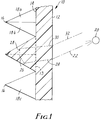
- IR-selective retroreflector 10 of the invention has front face 12 and rear face 14 with an array of cube-corner retroreflective elements 16 thereon.
- a great number of visible light reflecting cube-corner retroreflectors with a variety of variations of cube-corner elements are known. Illustrative examples are disclosed in the aforementioned U.S. Patent Nos. 3,712,706, 4,202,600, 4,243,618, 4,588,258, and 4,775,219. It will be understood that IR-selective retroreflectors, made in accordance with this invention, may be made in a variety of embodiments with desired retroreflective patterns and orientations based on the disclosures of these references and related techniques known to those skilled in the art.
- each of cube-corners 16 has three facets or sides 18a, 18b, and 18c.
- Light source 20 e.g., the headlights of an approaching vehicle, emits light beam 22 which is incident to front surface 12. If light 22 is incident to front surface 12 at a sufficiently low angle to the normal at the point of incidence, i.e., the "critical angle", the incident light refracts into article 10, shown as ray 24.
- critical angle is meant that angle at which light in an optically dense medium encountering a surface with a less optically dense medium is totally reflected internally from the surface rather than entering the optically less dense medium.
- the internally transmitted light follows path 24 until encountering facet 18a. Because the angle of the path 24 exceeds the critical angle in relationship to facet 18a, the light is internally reflected from the surface 18a and remaining within the article 10 and following path 26. The light continues on path 26 until encountering facet 18b. Because the angle between facet 18b and the path 26 exceeds the critical angle, the light is again internally reflected within the sheet 10 and begins traveling along path 28 until encountering facet 18c. Because the angle between facet 18c and the path 28 exceeds the critical angle, the light is again internally reflected and begins traveling along path 30 back toward front face 12. Path 30 is slightly offset from and parallel to path 24. The light continues on path 30 until re-encountering front face 12 at an angle less than the critical angle. The light exits through the front face 12 and is returned back toward light source 20 along path 32. Path 32 is slightly offset from and parallel to the path 22 of the original incident light.
- Pathlength is used herein to mean the sum of the individual extents or lengths of the series of paths traveled by light retroreflected by the retroreflector within the retroreflector. In the illustrative drawing, the pathlength is the sum of paths 24, 26, 28, and 30.
- the minimum pathlength i.e., the minimum length that light which is retroreflected by the article must travel within the retroreflector is approximately equal to twice the thickness of the sheeting between the front face 12 and base plane 13 plus twice the height of cube-corner elements 16.
- Selective pathlength is used herein to mean the portion of the pathlength which is within IR-selective portions of the retroreflector.
- Retroreflectors of the present invention differ from previously known cube-corner retroreflectors in that the cube-corner elements are IR-selective.
- the retroreflector is formed from a material which contains a polymer, typically transmissive to both visible light and infrared light material, and a colorant (i.e., a dye) or combination of colorants sufficient to absorb, over the extent of the minimum pathlength, substantially all of the visible wavelength components of the incident light while transmitting observable portions of infrared light.
- the polymeric matrix typically absorbs at least about 90 percent, preferably at least about 99 percent, and more preferably at least about 99.5 percent, of all wavelengths of visible light, i.e., light having a wavelength between about 400 mu and about 700 mu.
- the matrix transmits at least about 25 percent, preferably at least about 50 percent, more preferably at least about 90 percent, and most preferably at least about 95 percent of all wavelengths of infrared radiation, i.e., light having wavelength between about 750 mu and about 1100 mu.
- the matrix absorb at least about 99.5 percent of all wavelengths of light between about 380 mu and about 750 mu.
- Polycarbonates typically exhibit tough, durable character whereas polyacrylics typically exhibit greater retention of properties even when subjected to high colorant loadings.
- Colorants which may be used herein include dyes and pigments which may be dissolved or dispersed, respectively, in the polymer and absorb at least some portions of visible light absorption while permitting transmission of at least some infrared light.
- a single colorant which strongly absorbs all visible light and is highly transmissive to infrared light. While a single colorant with these ideal properties has not yet been identified or synthesized by the inventors, such properties can be obtained from mixtures of known dyes and/or pigments. Accordingly, two or more colorants will typically be employed to absorb visible light.
- the retroreflector may retroreflect most of the IR spectrum or portions thereof may be blocked.
- the colorant(s) and polymer should be compatible, i.e., the polymer should be capable of acting as a medium in which sufficient amounts of colorant(s) are dissolved or dispersed to absorb visible light as desired without undesirably degrading the properties of the polymer or resultant matrix.
- the colorant will be stable within the matrix and will not tend to bloom or migrate therefrom.
- dyes which are believed to be suitable for use herein include the following, identified by the Colour Index (“C.I.”) Generic Name assigned by the Society of Dyers and Colourists and the American Association of Textile Chemists and Colorists (as noted in the Colour Index, third Edition, 1982):
- Pigments used in IR-selective retroreflectors are preferably of small particle size, i.e., below about 3 to 4 microns typically, to facilitate dispersion in the polymeric matrix and ensure that they are sufficient transparent to permit desired retroreflection of infrared light by the resultant article.
- Illustrative examples of pigments which are believed to be suitable herein include LITHOSOLTM Fast Scarlet (red), Benzedine Yellow, HELIOGENTM Blue series, C.I. Pigment Green 7 (a copper thiocyanine), C.I. Pigment Blue 15 (a copper thiocyanine), C.I. Pigment Red 167 (an anthroquinone), and C.I. Pigment Yellow 89 (a disazo).
- combinations of two or more colorants are necessary to provide desired visible light absorption.
- Suitable combinations of colorants for use herein can be selected by first considering the absorption spectra of a first colorant. Within the absorption spectra of the first colorant, wavelengths can be determined in which the colorant is strongly absorbing and other wavelengths can be determined in which the colorant is weakly absorbing. A second colorant for the mixture is then selected based upon its ability to absorb the wavelengths not absorbed (i.e., transmitted) by the first colorant. It may be necessary to select a third and possibly a fourth and even a fifth colorant for the mixture to assure that strong absorption can be provided at all visible light wavelengths.
- mixtures of two, three, or four colorants are sufficient to absorb substantially all visible light wavelengths. It will be understood that it is the optical properties of the colorant in the polymeric matrix, rather than the specific chemical or chemical structures, of the colorant (or colorant mixture), which are essential to the present invention.
- Relative proportions of colorants in the mixture can be readily determined by trial and error. While it is possible to roughly estimate the relative proportions, it is believed that the concentrations of colorants employed are at or approaching concentrations at which Lambert's Law offers only limited guidance.
- the minimum thickness of a smooth-sided sheet (or blank) needed to form a cube-cornered structure via embossing is approximately one-third the depth of the desired cube-cornered structure.
- the pathlength of such a cube-cornered structure is approximately two times the depth of the cube-cornered structure.
- the pathlength of a smooth-sided sheet is at least about two times the thickness of the sheet (normal to the surface).
- Retroreflectors exhibiting the preferred high absorption of visible light at all visible light wavelengths typically appear generally black. Retroreflectors which are less effective visible light absorbers will appear colored. Verification of a retroreflector's ability to retroreflect infrared light can be accomplished by observing the retroreflector in a darkened room through an infrared viewing device incorporating both an infrared illumination source and an infrared viewer.
- the FIND-R-SCOPETM Viewer available from F.J.W. Industries of Mt. Prosperity, New York, is an illustrative example of such devices.
- IR-selective retroreflectors may also be evaluated by observation with an RI-1000 License Plate Reader available from Minnesota Mining and Manufacturing Company ("3M") of St. Paul, Minnesota.
- 3M Minnesota Mining and Manufacturing Company
- Such a reader can be fitted with a filter to eliminate passage of light with wavelengths below 850 mu at both the illumination source and the camera lens. It is helpful to also include a filter to prevent passage of light above 910 mu wavelength in order to limit the band of light measured, permitting a more standardized assessment of the unfiltered wavelengths.
- the camera measures retroreflected light from a small area of a sheeting sample being tested and quantifies the area as the retroreflected light detected by one pixel of the camera screen. The results are presented on a gray scale (non-linear) of from 20 to 255 with 255 being the maximum retroreflection and 20 being no detectable retroreflection.
- the cube-corners be encapsulated with a sealing film such as is disclosed in the aforementioned U.S. Patent No. 4,025,159. If encapsulated, a layer of adhesive may be applied to the back side of the sealing film to provide a means for securing the retroreflector to a desired substrate.
- the surfaces of the cube-corner elements may be metallized, e,g, with silver or aluminum, to modify the retroreflective performance of the article, and also eliminate the need for a seal film.
- a layer of adhesive may be applied to the back side of the metal layer.
- retroreflective brightness of visible light was measured using a retroluminometer as described in U.S. defensive publication no. T987,003 at a divergence angle of about 0.2° and at an entrance angle of about -4°.
- a cube-corner retroreflector was made with an IR-selective polymeric matrix made from a composition comprising 100. grams of red pellets, 16.60 grams of yellow pellets, 50. grams of violet pellets, and 33.40 grams of green pellets.
- the pellet mixture was re-extruded into a sheet (referred to below as a "blank") approximately 75 microns (3 mils) thick with two smooth sides.
- the second extruder was a small Haake single-screw extruder coupled to a 5-inch (12.7 cm) flat film die.
- the die temperature was 260°C (500°F) operated at a film take-off speed of about 80 to about 125 feet/minute (24 to 38 meters/minute).
- the melt temperature was about 184°C (364°F). Because of difficulties in controlling the sheet thickness, some variation in thickness occurred.
- the average thickness was about 94 microns (3.75 mils).
- This blank was then embossed using a platen press to form cube-corner retroreflective elements in one side.
- An additional sheet of clear PMMA with two smooth sides (referred to herein as the body), about 75 microns (3 mils) in thickness, was simultaneously inserted with the colored sheet into the embossing press against the smooth platen and laminated to the smooth side of the embossed sheet to improve the structural integrity of the resultant cube-cornered sheeting.
- the operation involved about 10 seconds of preheating to a temperature approaching 188°C (370°F) followed by about 20 seconds of embossing, followed by about 8 minutes of cooling time.
- the embossing platen had a pattern which produced slightly canted, three sided cube corner elements about 175 microns (7 mils) in height, with multi-non-orthagonal modifications in accordance with the aforementioned U.S. Patent Nos. 4,588,258 and 4,775,219.
- IR-selective retroreflectors were prepared as in Example 1, except that the proportions of the various colored pellets were altered as indicated in Table 1. Because of variations in smooth sheet extrusions, average thickness of each blank is shown in Table II.
- Example Red Yellow Green Violet Clear 1 100.0 16.60 33.40 50.00 0.00 2 50.00 8.30 16.70 25.00 100.00 3 25.00 4.15 8.35 12.50 150.00 4 120.00 13.40 66.60 0.0 0.0 5 146.60 0.0 53.40 0.0 0.0 A 0.0 0.0 0.0 0.0 200.00
- Table II Example Blank1 Body2 Pathlength3 1 3.7 2.9 16.84 2 3.1 3.3 15.54 3 3.0 3.3 15.34 4 3.8 3.3 17.04 5 3.3 3.1 15.94 A 2.7 2.7 0.00 1 Average thickness in mils of blank. 2 Average thickness in mils of body. 3 Pathlength in mils through IR-selective portion of article.
Landscapes
- Physics & Mathematics (AREA)
- General Physics & Mathematics (AREA)
- Optics & Photonics (AREA)
- Optical Elements Other Than Lenses (AREA)
- Illuminated Signs And Luminous Advertising (AREA)
Applications Claiming Priority (2)
| Application Number | Priority Date | Filing Date | Title |
|---|---|---|---|
| US835619 | 1992-02-13 | ||
| US07/835,619 US5200851A (en) | 1992-02-13 | 1992-02-13 | Infrared reflecting cube-cornered sheeting |
Publications (3)
| Publication Number | Publication Date |
|---|---|
| EP0555847A2 true EP0555847A2 (de) | 1993-08-18 |
| EP0555847A3 EP0555847A3 (en) | 1993-09-15 |
| EP0555847B1 EP0555847B1 (de) | 1997-04-23 |
Family
ID=25269993
Family Applications (1)
| Application Number | Title | Priority Date | Filing Date |
|---|---|---|---|
| EP93102146A Expired - Lifetime EP0555847B1 (de) | 1992-02-13 | 1993-02-11 | Würfelecken-Rückstrahlfolie für Infrarotlicht |
Country Status (5)
| Country | Link |
|---|---|
| US (1) | US5200851A (de) |
| EP (1) | EP0555847B1 (de) |
| JP (1) | JPH05346767A (de) |
| CA (1) | CA2088628A1 (de) |
| DE (1) | DE69309983T2 (de) |
Cited By (6)
| Publication number | Priority date | Publication date | Assignee | Title |
|---|---|---|---|---|
| WO2001079897A3 (en) * | 2000-04-13 | 2003-02-06 | 3M Innovative Properties Co | Cube corner retroreflective article with enhanced pigmentation |
| DE10228013A1 (de) * | 2002-06-22 | 2004-01-15 | Hans-Erich Sen. Gubela | Teiltransmissionsreflektor und optisches Sicherheitssensorsystem |
| US6877866B2 (en) | 1997-12-01 | 2005-04-12 | Reflexite Corporation | Multi-orientation retroreflective structure |
| WO2006074766A1 (de) * | 2005-01-14 | 2006-07-20 | Röhm Gmbh | Witterungsstabile folie zur gelbeinfärbung retroreflektierender formkörper |
| WO2007005357A1 (en) * | 2005-06-29 | 2007-01-11 | 3M Innovative Properties Company | Transparent, wavelength-selective retroreflector |
| WO2019172978A3 (en) * | 2017-12-27 | 2020-01-09 | 3M Innovative Properties Company | Infrared reflector and method of forming same |
Families Citing this family (40)
| Publication number | Priority date | Publication date | Assignee | Title |
|---|---|---|---|---|
| US5621571A (en) * | 1994-02-14 | 1997-04-15 | Minnesota Mining And Manufacturing Company | Integrated retroreflective electronic display |
| FR2722886B1 (fr) * | 1994-07-25 | 1996-09-27 | Laserdot | Procede et dispositif pour l'identification aerienne de nuit de zones du sol |
| US5920429A (en) * | 1995-09-29 | 1999-07-06 | Minnesota Mining And Manufacturing Company | Fluorescent dye blends |
| US5672643A (en) * | 1995-09-29 | 1997-09-30 | Minnesota Mining And Manufacturing Company | Fluorescent dye blends |
| US5674622A (en) * | 1995-09-29 | 1997-10-07 | Minnesota Mining And Manufacturing Company | Fluorescent dye blends |
| US6157486A (en) * | 1998-01-13 | 2000-12-05 | 3M Innovative Properties Company | Retroreflective dichroic reflector |
| US6024455A (en) * | 1998-01-13 | 2000-02-15 | 3M Innovative Properties Company | Reflective article with concealed retroreflective pattern |
| JP3957986B2 (ja) * | 2000-03-31 | 2007-08-15 | シャープ株式会社 | 反射型表示装置 |
| JP3612702B2 (ja) * | 2000-10-05 | 2005-01-19 | 日産自動車株式会社 | 赤外線透過膜及びこれを用いた赤外線センサーカバー |
| US6843571B2 (en) * | 2002-06-11 | 2005-01-18 | 3M Innovative Properties Company | Methods of making a master and replicas thereof |
| US6935756B2 (en) * | 2002-06-11 | 2005-08-30 | 3M Innovative Properties Company | Retroreflective articles having moire-like pattern |
| US7629967B2 (en) | 2003-02-14 | 2009-12-08 | Next Holdings Limited | Touch screen signal processing |
| US8456447B2 (en) | 2003-02-14 | 2013-06-04 | Next Holdings Limited | Touch screen signal processing |
| US8508508B2 (en) * | 2003-02-14 | 2013-08-13 | Next Holdings Limited | Touch screen signal processing with single-point calibration |
| US7538759B2 (en) | 2004-05-07 | 2009-05-26 | Next Holdings Limited | Touch panel display system with illumination and detection provided from a single edge |
| WO2005114268A2 (en) * | 2004-05-12 | 2005-12-01 | Reflexite Corporation | Retroreflective structures |
| US7387393B2 (en) * | 2005-12-19 | 2008-06-17 | Palo Alto Research Center Incorporated | Methods for producing low-visibility retroreflective visual tags |
| US7727418B2 (en) * | 2006-06-19 | 2010-06-01 | Sabic Innovative Plastics Ip B.V. | Infrared transmissive thermoplastic composition, and articles formed therefrom |
| US8113434B2 (en) * | 2006-06-30 | 2012-02-14 | Britta Technologies, Llc | Passive electro-optical identification tags |
| CN101100520A (zh) * | 2006-07-04 | 2008-01-09 | 谢基生 | 可透红外光的黑色塑料制品的制作方法和应用 |
| WO2008128096A2 (en) | 2007-04-11 | 2008-10-23 | Next Holdings, Inc. | Touch screen system with hover and click input methods |
| US7547105B2 (en) * | 2007-07-16 | 2009-06-16 | 3M Innovative Properties Company | Prismatic retroreflective article with cross-linked image layer and method of making same |
| AU2008280953A1 (en) | 2007-08-30 | 2009-03-19 | Next Holdings Ltd | Optical touchscreen with improved illumination |
| WO2009029764A1 (en) * | 2007-08-30 | 2009-03-05 | Next Holdings, Inc. | Low profile touch panel systems |
| US8405636B2 (en) | 2008-01-07 | 2013-03-26 | Next Holdings Limited | Optical position sensing system and optical position sensor assembly |
| PL2238485T3 (pl) * | 2008-01-14 | 2022-04-19 | Avery Dennison Corporation | Reflektor odblaskowy do użytku w zastosowaniach ekranów dotykowych i układach do wykrywania położenia |
| WO2009137355A2 (en) * | 2008-05-06 | 2009-11-12 | Next Holdings, Inc. | Systems and methods for resolving multitouch scenarios using software filters |
| US8248691B2 (en) * | 2008-05-30 | 2012-08-21 | Avery Dennison Corporation | Infrared light transmission film |
| US20100225588A1 (en) * | 2009-01-21 | 2010-09-09 | Next Holdings Limited | Methods And Systems For Optical Detection Of Gestures |
| US20100229090A1 (en) * | 2009-03-05 | 2010-09-09 | Next Holdings Limited | Systems and Methods for Interacting With Touch Displays Using Single-Touch and Multi-Touch Gestures |
| US9519087B2 (en) * | 2009-10-16 | 2016-12-13 | 3M Innovative Properties Company | Prismatic retroreflective sheeting with reduced retroreflectivity of infra-red light |
| WO2011046953A1 (en) | 2009-10-16 | 2011-04-21 | 3M Innovative Properties Company | Retroreflective sheeting and license plate with reduced retroreflectivity at high entrance angles |
| US9098150B2 (en) | 2009-12-11 | 2015-08-04 | Avery Dennison Corporation | Position sensing systems for use in touch screens and prismatic film used therein |
| JP6074128B2 (ja) * | 2010-04-15 | 2017-02-01 | デクセリアルズ株式会社 | 光学体およびその製造方法、日射遮蔽部材、窓材、内装部材ならびに建具 |
| US20110279411A1 (en) * | 2010-05-17 | 2011-11-17 | Nitto Denko Corporation | Optical waveguide and optical touch panel |
| KR101159179B1 (ko) * | 2010-10-13 | 2012-06-22 | 액츠 주식회사 | 터치 스크린 시스템 및 그 제조 방법 |
| CN102967892B (zh) * | 2011-08-30 | 2015-12-02 | 原相科技股份有限公司 | 用于光学式触控装置的反光镜及使用该反光镜的光学式触控装置 |
| WO2014017095A1 (en) * | 2012-07-25 | 2014-01-30 | Panasonic Corporation | Low cost, non-intrusive, high accuracy head tracking apparatus and method |
| US9070057B2 (en) * | 2012-10-30 | 2015-06-30 | General Electric Company | Method and system for identification of assets |
| JP2020067291A (ja) * | 2018-10-22 | 2020-04-30 | 豊田合成株式会社 | 車載センサカバー |
Family Cites Families (23)
| Publication number | Priority date | Publication date | Assignee | Title |
|---|---|---|---|---|
| US2930893A (en) * | 1956-05-21 | 1960-03-29 | Lane B Carpenter | Long path infrared detection of atmospheric contaminants |
| US3190178A (en) * | 1961-06-29 | 1965-06-22 | Minnesota Mining & Mfg | Reflex-reflecting sheeting |
| US3374044A (en) * | 1964-11-03 | 1968-03-19 | Gen Dynamics Corp | Filtered wave-energy corner-reflector |
| US3563771A (en) * | 1968-02-28 | 1971-02-16 | Minnesota Mining & Mfg | Novel black glass bead products |
| US3712706A (en) * | 1971-01-04 | 1973-01-23 | American Cyanamid Co | Retroreflective surface |
| US3758193A (en) * | 1971-07-02 | 1973-09-11 | Minnesota Mining & Mfg | Infrared-transmissive, visible-light-absorptive retro-reflectors |
| US3830682A (en) * | 1972-11-06 | 1974-08-20 | Rowland Dev Corp | Retroreflecting signs and the like with novel day-night coloration |
| US4025159A (en) * | 1976-02-17 | 1977-05-24 | Minnesota Mining And Manufacturing Company | Cellular retroreflective sheeting |
| US4082414A (en) * | 1976-03-03 | 1978-04-04 | Pyreflex Corporation | Heat recuperation |
| US4202600A (en) * | 1978-04-24 | 1980-05-13 | Avery International Corporation | Diced retroreflective sheeting |
| US4576850A (en) * | 1978-07-20 | 1986-03-18 | Minnesota Mining And Manufacturing Company | Shaped plastic articles having replicated microstructure surfaces |
| UST987003I4 (en) * | 1978-07-31 | 1979-10-02 | Minnesota Mining And Manufacturing Company | Retroluminometer |
| US4243618A (en) * | 1978-10-23 | 1981-01-06 | Avery International Corporation | Method for forming retroreflective sheeting |
| US4588258A (en) * | 1983-09-12 | 1986-05-13 | Minnesota Mining And Manufacturing Company | Cube-corner retroreflective articles having wide angularity in multiple viewing planes |
| US4733236A (en) * | 1985-12-10 | 1988-03-22 | The United States Of America As Represented By The Secretary Of The Air Force | Space target with multi-spectral energy reflectivity |
| US4775219A (en) * | 1986-11-21 | 1988-10-04 | Minnesota Mining & Manufacturing Company | Cube-corner retroreflective articles having tailored divergence profiles |
| CA1262268A (fr) * | 1987-04-16 | 1989-10-10 | Raymond Lessard | Systeme de signalisation a l'infrarouge pour detecter une condition predeteriminee d'un dispositif a haute tension |
| US5066098A (en) * | 1987-05-15 | 1991-11-19 | Minnesota Mining And Manufacturing Company | Cellular encapsulated-lens high whiteness retroreflective sheeting with flexible cover sheet |
| IL87441A (en) * | 1988-08-12 | 1994-12-29 | Driver Safety Systems Ltd | Constant-deviation reflector |
| IL88243A0 (en) * | 1988-10-31 | 1990-07-12 | Israel Aircraft Ind Ltd | Corner cube assembly |
| US4957335A (en) * | 1989-05-26 | 1990-09-18 | Minnesota Mining And Manufacturing Company | Microsphere-based retroreflective articles with enhanced retroreflective brightness |
| US5138488A (en) * | 1990-09-10 | 1992-08-11 | Minnesota Mining And Manufacturing Company | Retroreflective material with improved angularity |
| US5128794A (en) * | 1990-12-31 | 1992-07-07 | Honeywell Inc. | Scanning laser helmet mounted sight |
-
1992
- 1992-02-13 US US07/835,619 patent/US5200851A/en not_active Expired - Lifetime
-
1993
- 1993-02-02 CA CA002088628A patent/CA2088628A1/en not_active Abandoned
- 1993-02-11 EP EP93102146A patent/EP0555847B1/de not_active Expired - Lifetime
- 1993-02-11 DE DE69309983T patent/DE69309983T2/de not_active Expired - Fee Related
- 1993-02-15 JP JP5025366A patent/JPH05346767A/ja active Pending
Cited By (13)
| Publication number | Priority date | Publication date | Assignee | Title |
|---|---|---|---|---|
| US6877866B2 (en) | 1997-12-01 | 2005-04-12 | Reflexite Corporation | Multi-orientation retroreflective structure |
| KR100787410B1 (ko) * | 2000-04-13 | 2007-12-21 | 쓰리엠 이노베이티브 프로퍼티즈 캄파니 | 재귀 반사 큐브 코너 시트 |
| WO2001079897A3 (en) * | 2000-04-13 | 2003-02-06 | 3M Innovative Properties Co | Cube corner retroreflective article with enhanced pigmentation |
| DE10228013A1 (de) * | 2002-06-22 | 2004-01-15 | Hans-Erich Sen. Gubela | Teiltransmissionsreflektor und optisches Sicherheitssensorsystem |
| EP1376160A3 (de) * | 2002-06-22 | 2004-06-23 | Hans-Erich Sen. Gubela | Teiltransmissionsreflektor und optisches Sicherheitssensorsystem |
| DE10228013B4 (de) * | 2002-06-22 | 2005-11-03 | Hans-Erich Sen. Gubela | Teiltransmissionsreflektor, Verwendung des Teiltransmissionsreflektors und optisches Sensorsystem |
| US7754317B2 (en) | 2005-01-14 | 2010-07-13 | Evonik Roehm Gmbh | Weather-resistant film for the yellow coloration of retro-reflective moulded bodies |
| CN1930218B (zh) * | 2005-01-14 | 2010-05-05 | 罗姆有限公司 | 用于将后向反射性模制品着黄色的耐候性膜片 |
| WO2006074766A1 (de) * | 2005-01-14 | 2006-07-20 | Röhm Gmbh | Witterungsstabile folie zur gelbeinfärbung retroreflektierender formkörper |
| TWI405796B (zh) * | 2005-01-14 | 2013-08-21 | Evonik Roehm Gmbh | 供回射性模塑品著黃色用之耐候性箔片 |
| WO2007005357A1 (en) * | 2005-06-29 | 2007-01-11 | 3M Innovative Properties Company | Transparent, wavelength-selective retroreflector |
| US8496339B2 (en) | 2005-06-29 | 2013-07-30 | 3M Innovative Properties Company | Transparent, wavelength-selective retroreflector |
| WO2019172978A3 (en) * | 2017-12-27 | 2020-01-09 | 3M Innovative Properties Company | Infrared reflector and method of forming same |
Also Published As
| Publication number | Publication date |
|---|---|
| DE69309983D1 (de) | 1997-05-28 |
| JPH05346767A (ja) | 1993-12-27 |
| US5200851A (en) | 1993-04-06 |
| EP0555847B1 (de) | 1997-04-23 |
| DE69309983T2 (de) | 1997-12-18 |
| CA2088628A1 (en) | 1993-08-14 |
| EP0555847A3 (en) | 1993-09-15 |
Similar Documents
| Publication | Publication Date | Title |
|---|---|---|
| EP0555847B1 (de) | Würfelecken-Rückstrahlfolie für Infrarotlicht | |
| EP0489561B1 (de) | Gegenstände, die dauerhafte Fluoreszenz zeigen | |
| EP0609880B1 (de) | Würfelecken-Retroreflektor mit Farbpartikeln | |
| CA2319155C (en) | Extended life fluorescence polyvinyl chloride sheeting | |
| US6045230A (en) | Modulating retroreflective article | |
| KR101133414B1 (ko) | 조절된 cap-y 를 가지는 역반사 시트 | |
| US8248691B2 (en) | Infrared light transmission film | |
| KR20120091205A (ko) | 적외광의 재귀반사도가 감소된 프리즘형 재귀반사성 시트류 | |
| KR102581087B1 (ko) | 재귀반사시트 | |
| US8034436B2 (en) | Fluorescent article having multiple layers | |
| WO2000047407A1 (en) | Extended life fluorescence polyvinyl chloride sheeting | |
| HK1006830B (en) | Articles exhibiting durable fluorescence |
Legal Events
| Date | Code | Title | Description |
|---|---|---|---|
| PUAI | Public reference made under article 153(3) epc to a published international application that has entered the european phase |
Free format text: ORIGINAL CODE: 0009012 |
|
| PUAL | Search report despatched |
Free format text: ORIGINAL CODE: 0009013 |
|
| AK | Designated contracting states |
Kind code of ref document: A2 Designated state(s): DE FR GB |
|
| AK | Designated contracting states |
Kind code of ref document: A3 Designated state(s): DE FR GB |
|
| 17P | Request for examination filed |
Effective date: 19940127 |
|
| 17Q | First examination report despatched |
Effective date: 19950529 |
|
| GRAG | Despatch of communication of intention to grant |
Free format text: ORIGINAL CODE: EPIDOS AGRA |
|
| GRAH | Despatch of communication of intention to grant a patent |
Free format text: ORIGINAL CODE: EPIDOS IGRA |
|
| GRAH | Despatch of communication of intention to grant a patent |
Free format text: ORIGINAL CODE: EPIDOS IGRA |
|
| GRAA | (expected) grant |
Free format text: ORIGINAL CODE: 0009210 |
|
| AK | Designated contracting states |
Kind code of ref document: B1 Designated state(s): DE FR GB |
|
| REF | Corresponds to: |
Ref document number: 69309983 Country of ref document: DE Date of ref document: 19970528 |
|
| ET | Fr: translation filed | ||
| PLBE | No opposition filed within time limit |
Free format text: ORIGINAL CODE: 0009261 |
|
| STAA | Information on the status of an ep patent application or granted ep patent |
Free format text: STATUS: NO OPPOSITION FILED WITHIN TIME LIMIT |
|
| 26N | No opposition filed | ||
| REG | Reference to a national code |
Ref country code: GB Ref legal event code: IF02 |
|
| PGFP | Annual fee paid to national office [announced via postgrant information from national office to epo] |
Ref country code: FR Payment date: 20030117 Year of fee payment: 11 |
|
| PGFP | Annual fee paid to national office [announced via postgrant information from national office to epo] |
Ref country code: GB Payment date: 20030205 Year of fee payment: 11 |
|
| PGFP | Annual fee paid to national office [announced via postgrant information from national office to epo] |
Ref country code: DE Payment date: 20030228 Year of fee payment: 11 |
|
| PG25 | Lapsed in a contracting state [announced via postgrant information from national office to epo] |
Ref country code: GB Free format text: LAPSE BECAUSE OF NON-PAYMENT OF DUE FEES Effective date: 20040211 |
|
| PG25 | Lapsed in a contracting state [announced via postgrant information from national office to epo] |
Ref country code: DE Free format text: LAPSE BECAUSE OF NON-PAYMENT OF DUE FEES Effective date: 20040901 |
|
| GBPC | Gb: european patent ceased through non-payment of renewal fee |
Effective date: 20040211 |
|
| PG25 | Lapsed in a contracting state [announced via postgrant information from national office to epo] |
Ref country code: FR Free format text: LAPSE BECAUSE OF NON-PAYMENT OF DUE FEES Effective date: 20041029 |
|
| REG | Reference to a national code |
Ref country code: FR Ref legal event code: ST |