EP0555851A2 - Zündsteuervorrichtung für eine elektronische Zündeinrichtung einer Brennkraftmaschine - Google Patents
Zündsteuervorrichtung für eine elektronische Zündeinrichtung einer Brennkraftmaschine Download PDFInfo
- Publication number
- EP0555851A2 EP0555851A2 EP93102158A EP93102158A EP0555851A2 EP 0555851 A2 EP0555851 A2 EP 0555851A2 EP 93102158 A EP93102158 A EP 93102158A EP 93102158 A EP93102158 A EP 93102158A EP 0555851 A2 EP0555851 A2 EP 0555851A2
- Authority
- EP
- European Patent Office
- Prior art keywords
- block
- ignition
- fact
- spark
- electric
- Prior art date
- Legal status (The legal status is an assumption and is not a legal conclusion. Google has not performed a legal analysis and makes no representation as to the accuracy of the status listed.)
- Withdrawn
Links
Images

Classifications
-
- F—MECHANICAL ENGINEERING; LIGHTING; HEATING; WEAPONS; BLASTING
- F02—COMBUSTION ENGINES; HOT-GAS OR COMBUSTION-PRODUCT ENGINE PLANTS
- F02P—IGNITION, OTHER THAN COMPRESSION IGNITION, FOR INTERNAL-COMBUSTION ENGINES; TESTING OF IGNITION TIMING IN COMPRESSION-IGNITION ENGINES
- F02P17/00—Testing of ignition installations, e.g. in combination with adjusting; Testing of ignition timing in compression-ignition engines
- F02P17/12—Testing characteristics of the spark, ignition voltage or current
-
- F—MECHANICAL ENGINEERING; LIGHTING; HEATING; WEAPONS; BLASTING
- F02—COMBUSTION ENGINES; HOT-GAS OR COMBUSTION-PRODUCT ENGINE PLANTS
- F02P—IGNITION, OTHER THAN COMPRESSION IGNITION, FOR INTERNAL-COMBUSTION ENGINES; TESTING OF IGNITION TIMING IN COMPRESSION-IGNITION ENGINES
- F02P17/00—Testing of ignition installations, e.g. in combination with adjusting; Testing of ignition timing in compression-ignition engines
- F02P17/10—Measuring dwell or antidwell time
-
- F—MECHANICAL ENGINEERING; LIGHTING; HEATING; WEAPONS; BLASTING
- F02—COMBUSTION ENGINES; HOT-GAS OR COMBUSTION-PRODUCT ENGINE PLANTS
- F02P—IGNITION, OTHER THAN COMPRESSION IGNITION, FOR INTERNAL-COMBUSTION ENGINES; TESTING OF IGNITION TIMING IN COMPRESSION-IGNITION ENGINES
- F02P3/00—Other installations
- F02P3/02—Other installations having inductive energy storage, e.g. arrangements of induction coils
- F02P3/04—Layout of circuits
- F02P3/045—Layout of circuits for control of the dwell or anti dwell time
- F02P3/0453—Opening or closing the primary coil circuit with semiconductor devices
- F02P3/0456—Opening or closing the primary coil circuit with semiconductor devices using digital techniques
-
- F—MECHANICAL ENGINEERING; LIGHTING; HEATING; WEAPONS; BLASTING
- F02—COMBUSTION ENGINES; HOT-GAS OR COMBUSTION-PRODUCT ENGINE PLANTS
- F02P—IGNITION, OTHER THAN COMPRESSION IGNITION, FOR INTERNAL-COMBUSTION ENGINES; TESTING OF IGNITION TIMING IN COMPRESSION-IGNITION ENGINES
- F02P3/00—Other installations
- F02P3/02—Other installations having inductive energy storage, e.g. arrangements of induction coils
- F02P3/04—Layout of circuits
- F02P3/05—Layout of circuits for control of the magnitude of the current in the ignition coil
- F02P3/051—Opening or closing the primary coil circuit with semiconductor devices
- F02P3/053—Opening or closing the primary coil circuit with semiconductor devices using digital techniques
Definitions
- the present invention relates to an ignition control device for an internal combustion engine electronic ignition system.
- Pollution control standards are now being issued practically worldwide for controlling all the factors responsible for the pollutants produced by internal combustion engines.
- the most effective solution for conforming with these standards is to equip the vehicle with electronic injection and ignition systems in conjunction with a catalytic muffler.
- electronic injection and ignition systems In view of the high cost of the materials used in the manufacture of catalytic mufflers, however, these must be safeguarded by ensuring optimum operation of the electronic injection and ignition systems.
- the most widely used electronic ignition systems are inductive discharge types wherein energy stored in the primary winding of the coil is transmitted by a switch device to the secondary winding connected to the spark plug electrodes. Allowing for conversion losses, the energy at the terminals of the secondary winding equals that stored in the primary.
- the energy stored in the primary winding and available in the secondary are also constant, so that maximum energy is supplied by the ignition system to the spark plug at all times and at any engine speed, even when the energy required may be less than maximum. Consequently, the ignition system and all the component parts (coil, plugs and electronic components) must be designed to operate continuously at maximum power. In addition to high energy consumption and the high cost of oversizing the components, currently used electronic ignition systems are also subject to severe wear of the component parts, which in turn impairs operation of the system as a whole, thus jeopardizing the catalytic muffler.
- an ignition control device for an internal combustion engine electronic ignition system; said system comprising a coil, the primary winding of which presents a first terminal connected to a first reference voltage, and a second terminal connected to a reference ground via a switch device, and the secondary winding of which supplies an ignition block; characterized by the fact that it comprises: means, which, for the spark of each operating cycle of said ignition block, provides for detecting first signals relative to the energy available between the electrodes of said ignition block; means for processing said first signals and computing a quantity representing the energy available between the electrodes of said ignition block; means for computing the speed of said engine as a function of a number of second signals; means for comparing said quantity with values considered optimum for each speed of said engine and stored in an internal memory block; and means for controlling the charge of said primary winding via a third signal resulting from said comparison, and for driving said switch device, so as to automatically control the energy to be made available between the electrodes of said ignition block for the spark of the cycle following that in which said first signals are detected
- Number 1 in Fig.1 indicates an ignition control device for the electronic ignition system 2 of an internal combustion engine.
- System 2 comprises a coil 3, the primary winding 4 of which presents a first terminal connected to reference voltage V1ref (normally equal to the battery voltage), and a second terminal connected to a reference ground via a known transistorized switch device 5.
- Coil 3 also presents a secondary winding 6 having a first terminal connected to a block 7 (representing one or more spark plugs and, in the latter case, also an ignition distributor), and a second terminal connected to a reference ground.
- the terminals of secondary winding 6 may be connected to the electrode of a respective plug.
- one of two neighbouring windings is supplied with variable current, current is induced in the other due to variation of the flux linkage. This phenomenon is further enhanced if the two windings are wound about the same magnetic core, thus enabling low-voltage energy to be converted into high-voltage energy, and the production of violent discharges in the form of sparks between the plug electrodes.
- the output energy of coil 3 is expressed as the integral of the product of the hold voltage and the arc current within the duration of the arc.
- the voltage required between the plug electrodes is determined by engine load and the gap between the plug electrodes, and increases proportionally alongside an increase in hold voltage and a reduction in the duration of the arc, which phenomena are accentuated alongside an increase in engine load.
- direct or indirect detection of the duration of the arc may thus be employed as a basis for diagnosing correct operation of ignition system 2 and particularly system components such as the spark plug. Such detection may also be employed for driving switch device 5 and so controlling current I1 in primary winding 4, for enabling system 2 to adapt automatically to the optimum energy value actually required by the engine.
- the duration of the arc is deducible from the voltage at the terminals of secondary winding 6, the current of secondary winding 6, and the voltage at the terminals of primary winding 4; and the voltage detected at the terminals of primary winding 4 is used by device 1 for measuring the duration of the arc.
- the latter may be correlated with the current of secondary winding 6 and, consequently, with the energy at the plug.
- Switch device 5 comprises a Darlington transistor 11 with the collector connected to one terminal of primary winding 4, the emitter connected to the reference ground, and the base connected to the collector via a Zener diode 12. The base of transistor 11 is driven by an electric block 13, the functions of which are described later on, and which, together with switch device 5, constitutes an ignition module 14.
- the collector voltage of transistor 11 is known to be close to zero only when the transistor is saturated, and to be equal to or greater than voltage V1ref when transistor 11 is off. High voltage is generated in secondary winding 6 upon the base control current of transistor 11 being cut off for disabling the emitter-collector circuit, at which point the collector voltage reaches the maximum value limited by diode 12. Subsequently, the collector voltage reflects the high voltage at the terminals of secondary winding 6, with hold values of a few tens of volts throughout the duration of the arc between the plug electrodes.
- device 1 comprises an electric block 15 defined by an operational amplifier (functioning as a comparator) having two inputs connected to respective terminals of primary winding 4, for determining the difference between the collector voltage and reference voltage V1ref.
- Block 15 generates a positive output signal when the collector voltage is sufficiently higher than reference voltage V1ref, which situation persists as long as high voltage is present at the terminals of secondary winding 6.
- block 15 generates a positive pulse, the duration of which is closely related to that of the electric arc between the plug electrodes.
- Device 1 also comprises an electric block 16 having an integrating block 17, a signal hold block 18, and an electronic switch 21 for connecting and disconnecting blocks 17 and 18.
- Block 17 presents two inputs, one connected to the output of block 15 and the other to reference voltage V2ref, and an output connected to the common terminal 22 of switch 21.
- the output pulse from block 15 drives block 17, which provides for proportionally converting the duration of the pulse into a voltage signal.
- a capacitor 23 with an analog storage function is provided parallel to and between the output and pulse input of block 17.
- the pulse input of block 17 is also connected to terminal 24 of switch 21.
- block 17 is shown in the initialization state.
- device 1 As connection and disconnection of blocks 17 and 18, i.e. control of switch 21, must be synchronized with the collector voltage, device 1 comprises an actuator block 25 which, depending on analysis of the collector voltage, generates a signal for controlling switch 21.
- block 18 During the primary winding charge phase, i.e. with transistor 11 saturated, block 18 is isolated from block 17, during which time, as shown clearly in Fig.1, block 17 is initialized by virtue of capacitor 23 being shortcircuited and discharged.
- actuator block 25 Upon the collector voltage exceeding reference voltage V5ref, actuator block 25 triggers switch 21 so as to disconnect terminals 22 and 24 and connect terminal 22 to a terminal 26 connected to one input of block 18.
- switch 21 may be controlled by block 25 in the presence of the base control current of transistor 11.
- Block 18 presents a first input connected both to terminal 26 of switch 21 and, via a capacitor 27, to a reference ground; an output connected to electric block 28; and a second input connected to its own output.
- block 18 saves the integration value received from block 17 during the previous connection, so that, at the end of the electric arc, the output of block 16, and more specifically the output of block 18, supplies an analog quantity proportional to the duration of the arc.
- Block 28 acts as an output interface for the analog signal generated by block 16, and, consisting substantially of an amplifier, provides, on the basis of reference voltage V3ref, for amplifying and so achieving an appropriate volume range of the analog signal.
- Block 28 presents an output connected both to an electronic control system 31 and to an electric comparing block 32 in turn connected to system 31.
- block 32 constantly controls the integration value, so as to inform system 31 of the absence or insufficient duration of the spark.
- system 31 diagnoses the spark and, in the event of a defect, informs the user via alarm 33, which may consist singly of a sound alarm, alarm light or display, or a combination of all three.
- the spark defect may be caused by spark failure, severe wear of the spark plug, too wide a gap between the plug electrodes, fuel pressure peaks inside the cylinder, or by failure or wear of one or more components of system 2.
- system 31 may also be supplied with information detected by engine speed and stroke sensors, thus enabling it to correlate the incoming signals from blocks 28 and 32 to a specific spark plug.
- System 31 is also supplied with a number of electric signals relative to operation of the component parts and all the chemical-physical parameters of the engine, and which enable it to determine the operating speed of the engine.
- system 31 determines the energy available at the spark plug, and, on the basis of a map stored in an internal memory block and containing optimum energy values in relation to engine speed, compares the available energy value with the optimum value for the engine speed in question. The outcome of the comparison gives rise to a signal, which is fed back to ignition module 14 for automatically controlling the charge of primary winding 4 and so automatically controlling the energy to be supplied to the plug for the next spark following the one whose duration has been detected.
- Block 13 then activates switch device 5.
- the spark also depends on the physical-chemical condition of the air-fuel mixture, which constitutes the dielectric between the electrodes.
- the spark also depends on the strength, pressure and temperature of the mixture. Any variation in the physical-chemical condition of the mixture, such as high pressure peaks in the cylinder, may be compensated by system 31 increasing the energy to be made available at the plug.
- system 31 provides for controlling any deviation between the optimum and detected energy values. By comparing said deviation with a given threshold value, system 31 is able to determine whether the duration of the arc is restored automatically to the optimum value by increasing the energy made available to the plug.
- system 31 diagnoses faulty operation of ignition system 2, due to wear of the plug, fouling of the electrodes, impaired system components, broken cables, etc.
- System 31 may be provided with means for storing the spark duration signals for considerable periods of time, and so processing statistical data relative to the signal values, for enabling more accurate diagnosis of long-term operation of ignition system 2 and its components.
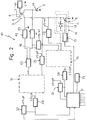
- Number 41 in Fig.2 indicates an ignition control device for an internal combustion engine electronic ignition system 2 featuring a coil 3, or rather a secondary winding 6, for each spark plug, which, in this case also, is shown schematically by block 7.
- Device 41 differs substantially from device 1 in that it provides for detecting the energy available at the plug, or rather a specular image, as opposed to the duration of the arc from which to deduce said energy. As compared with device 1, device 41 thus provides for more accurately controlling switch device 5 and, consequently, the energy supplied to the plug.
- a further characteristic of device 41 is that it provides for detecting additional quantities, thus enabling more accurate diagnosis.
- Device 41 detects current I2pk and voltage Vm2, and provides for integrating the product of the two.
- device 41 comprises an electric block 42 input-connected to the terminal of primary winding 4 connected via device 5 to the reference ground, which block 42 provides for attenuating and filtering the input quantity, and as such may consist of a straightforward voltage divider.
- the input quantity consists of the collector voltage, which, as stated, reflects the plug voltage, so that the output quantity of block 42 is an image of voltage Vm2.
- Device 41 also comprises an amplifying block 43, the input of which is connected to the terminal of secondary winding 6 connected to the reference ground.
- Block 43 is supplied with a quantity which is an image of current I2pk, this current being detected as the voltage drop over a resistor 44 of known value connected between secondary winding 6 and the reference ground.
- the outputs of blocks 42 and 43 are connected to an analog multiplying block 45, which provides for multiplying the input quantities, while at the same time taking into account the constants inherent in blocks 42 and 43, and which supplies an output quantity which is an image of the energy available at the plug.
- the signal relative to said quantity is then processed in the same way as the spark duration signal of device 1, for which purpose, block 45 is connected to a block 16, the switch 21 of which is controlled by blocks 25, 28 and 32.
- the reference voltages of said blocks though indicated in the same way in Fig.2, may obviously differ as compared with those of device 1.
- the output of block 43 is connected to a block 46 substantially defined by an operational amplifier, which compares the input signal with a reference voltage V6ref, and the difference signal at the output of which is processed in the same way as described above by a further block 16 with a block 25, and by further blocks 28 and 32. What was said previously relative to a possible difference in reference voltage also applies to these blocks.
- Device 41 may, of course, present one block 25 for simultaneously controlling switches 21 of both blocks 16.
- Control system 31 is thus supplied with signals relative to both the energy available at the plug and current I2pk of secondary winding 6, and, as in the case of device 1, on the basis of the spark duration and plug energy signal, controls module 14 for automatically controlling the charge of primary winding 4 and, consequently, the energy to be supplied to the plug for the next spark following that to which the signal applies. On the basis of all the incoming signals, system 31 also provides for diagnosing system 2 and its components.
- the device according to the present invention provides for supplying signals updated as of the previous cycle, so as to automatically control energy supply to the plug as a function of engine demand in the foregoing cycle, thus enabling energy saving, by virtue of the average spark energy requirement of the engine undoubtedly being less than the maximum value supplied at all times by currently used ignition systems.
- the ignition system components plugs, coil, electronic components, etc.
- the mean current in the secondary winding of the coil provides for extending the working life of the plug.
- the device according to the present invention provides for reducing both the running and production cost of the ignition system.
- the device according to the present invention also provides for further advantages in terms of operation and long-term protection of catalytic mufflers, by automatically compensating for wear of the spark plugs, which otherwise results in increased energy demand for the spark. What is more, by establishing minimum and maximum energy thresholds in the control system for each engine speed, it is possible, not only to diagnose operation and the condition of the ignition system and components, but also to provide for long-term protection of the catalytic muffler and ignition system by informing the user whenever said thresholds are exceeded.
- component blocks of devices 1 and 41 may be fully or partially integrated in control system 31, so that the functions of said blocks may be performed by programs inside control system 31.
Landscapes
- Engineering & Computer Science (AREA)
- Chemical & Material Sciences (AREA)
- Combustion & Propulsion (AREA)
- Mechanical Engineering (AREA)
- General Engineering & Computer Science (AREA)
- Ignition Installations For Internal Combustion Engines (AREA)
Applications Claiming Priority (2)
| Application Number | Priority Date | Filing Date | Title |
|---|---|---|---|
| ITBO920049A IT1260135B (it) | 1992-02-13 | 1992-02-13 | Dispositivo di controllo dell'accensione per un sistema di accensione elettronica di un motore endotermico |
| ITBO920049 | 1992-02-13 |
Publications (2)
| Publication Number | Publication Date |
|---|---|
| EP0555851A2 true EP0555851A2 (de) | 1993-08-18 |
| EP0555851A3 EP0555851A3 (en) | 1994-07-06 |
Family
ID=11337993
Family Applications (1)
| Application Number | Title | Priority Date | Filing Date |
|---|---|---|---|
| EP19930102158 Withdrawn EP0555851A3 (en) | 1992-02-13 | 1993-02-11 | Ignition control device for an internal combustion engine electronic ignition system |
Country Status (2)
| Country | Link |
|---|---|
| EP (1) | EP0555851A3 (de) |
| IT (1) | IT1260135B (de) |
Cited By (10)
| Publication number | Priority date | Publication date | Assignee | Title |
|---|---|---|---|---|
| GB2307516A (en) * | 1995-11-15 | 1997-05-28 | British Gas Plc | Internal combustion engine ignition system |
| DE19608526A1 (de) * | 1996-03-06 | 1997-09-11 | Bremicker Auto Elektrik | Verfahren zur Regelung der Mindestzündenergie |
| WO1998019066A1 (de) * | 1996-10-29 | 1998-05-07 | Ficht Gmbh & Co. Kg | Zündvorrichtung und verfahren zum betreiben einer zündvorrichtung |
| DE10127363C1 (de) * | 2001-06-06 | 2002-10-10 | Siemens Ag | Zündvorrichtung, Steuergerät und Zündanlage für eine Brennkraftmaschine |
| WO2002099273A1 (de) | 2001-06-06 | 2002-12-12 | Siemens Aktiengesellschaft | Zündanlage für eine brennkraftmaschine |
| WO2011113431A1 (de) * | 2010-03-17 | 2011-09-22 | Motortech Gmbh | Zündverfahren und zündanlage dafür |
| CN104110312A (zh) * | 2013-04-22 | 2014-10-22 | 福特环球技术公司 | 用于向发动机提供火花的系统和方法 |
| US9840971B2 (en) | 2013-08-15 | 2017-12-12 | Ford Global Technologies, Llc | Variable displacement engine control system and method |
| US9879625B2 (en) | 2013-08-15 | 2018-01-30 | Ford Global Technologies, Llc | Variable displacement engine control system and method |
| IT201800007781A1 (it) * | 2018-08-02 | 2020-02-02 | Eldor Corp Spa | Metodo e dispositivo di rilevamento della tensione di rottura del dielettrico tra gli elettrodi di una candela collegata ad una bobina di accensione per un sistema di accensione di un cilindro in un motore a combustione interna |
Family Cites Families (4)
| Publication number | Priority date | Publication date | Assignee | Title |
|---|---|---|---|---|
| DE2759154C2 (de) * | 1977-12-31 | 1985-11-14 | Robert Bosch Gmbh, 7000 Stuttgart | Zündeinrichtung für Brennkraftmaschinen |
| US4380989A (en) * | 1979-11-27 | 1983-04-26 | Nippondenso Co., Ltd. | Ignition system for internal combustion engine |
| IT1208855B (it) * | 1987-03-02 | 1989-07-10 | Marelli Autronica | Sistema di accensione ad energia di scintilla variabile per motori acombustione interna particolarmente per autoveicoli |
| US5054461A (en) * | 1990-12-31 | 1991-10-08 | Motorola, Inc. | Ionization control for automotive ignition system |
-
1992
- 1992-02-13 IT ITBO920049A patent/IT1260135B/it active IP Right Grant
-
1993
- 1993-02-11 EP EP19930102158 patent/EP0555851A3/en not_active Withdrawn
Cited By (26)
| Publication number | Priority date | Publication date | Assignee | Title |
|---|---|---|---|---|
| US5896848A (en) * | 1995-11-15 | 1999-04-27 | Bg Plc | Ignition control circuit for internal combustion engine |
| GB2307516B (en) * | 1995-11-15 | 1999-06-02 | British Gas Plc | Ignition control circuit for internal combustion engines |
| GB2307516A (en) * | 1995-11-15 | 1997-05-28 | British Gas Plc | Internal combustion engine ignition system |
| DE19608526C2 (de) * | 1996-03-06 | 2003-05-15 | Bremi Auto Elek K Bremicker Gm | Verfahren zur Regelung der Mindestzündenergie bei einer Brennkraftmaschine |
| DE19608526A1 (de) * | 1996-03-06 | 1997-09-11 | Bremicker Auto Elektrik | Verfahren zur Regelung der Mindestzündenergie |
| FR2745856A1 (fr) * | 1996-03-06 | 1997-09-12 | Bremicker Auto Elektrik | Procede de regulation de l'energie minimale d'allumage |
| WO1998019066A1 (de) * | 1996-10-29 | 1998-05-07 | Ficht Gmbh & Co. Kg | Zündvorrichtung und verfahren zum betreiben einer zündvorrichtung |
| US6792926B2 (en) | 2001-06-06 | 2004-09-21 | Siemens Aktiengesellschaft | Ignition system for an internal combustion engine |
| WO2002099273A1 (de) | 2001-06-06 | 2002-12-12 | Siemens Aktiengesellschaft | Zündanlage für eine brennkraftmaschine |
| DE10127362A1 (de) * | 2001-06-06 | 2003-01-02 | Siemens Ag | Zündanlage für eine Brennkraftmaschine |
| WO2002099272A1 (de) * | 2001-06-06 | 2002-12-12 | Siemens Aktiengesellschaft | Zündvorrichtung, steuergerät und zündanlage für eine brennkraftmaschine |
| DE10127362C2 (de) * | 2001-06-06 | 2003-05-15 | Siemens Ag | Zündanlage für eine Brennkraftmaschine |
| DE10127363C1 (de) * | 2001-06-06 | 2002-10-10 | Siemens Ag | Zündvorrichtung, Steuergerät und Zündanlage für eine Brennkraftmaschine |
| US6799564B2 (en) | 2001-06-06 | 2004-10-05 | Siemens Aktiengesellschaft | Ignition device, controller and ignition unit for an internal combustion engine |
| KR100853053B1 (ko) | 2001-06-06 | 2008-08-19 | 지멘스 악티엔게젤샤프트 | 내연기관용 점화 시스템 |
| KR100869186B1 (ko) * | 2001-06-06 | 2008-11-18 | 지멘스 악티엔게젤샤프트 | 내연기관용 점화 장치, 제어기 및 점화 유닛 |
| WO2011113431A1 (de) * | 2010-03-17 | 2011-09-22 | Motortech Gmbh | Zündverfahren und zündanlage dafür |
| US8893692B2 (en) | 2010-03-17 | 2014-11-25 | Motortech Gmbh | Ignition method and ignition system therefor |
| CN104110312A (zh) * | 2013-04-22 | 2014-10-22 | 福特环球技术公司 | 用于向发动机提供火花的系统和方法 |
| US9840971B2 (en) | 2013-08-15 | 2017-12-12 | Ford Global Technologies, Llc | Variable displacement engine control system and method |
| US9879625B2 (en) | 2013-08-15 | 2018-01-30 | Ford Global Technologies, Llc | Variable displacement engine control system and method |
| IT201800007781A1 (it) * | 2018-08-02 | 2020-02-02 | Eldor Corp Spa | Metodo e dispositivo di rilevamento della tensione di rottura del dielettrico tra gli elettrodi di una candela collegata ad una bobina di accensione per un sistema di accensione di un cilindro in un motore a combustione interna |
| WO2020026128A1 (en) * | 2018-08-02 | 2020-02-06 | Eldor Corporation S.P.A. | Method and device for detecting the breakdown voltage between the electrodes of a spark plug connected to an ignition coil for a cylinder ignition system in an internal combustion engine |
| CN113366214A (zh) * | 2018-08-02 | 2021-09-07 | 艾尔多股份有限公司 | 用于检测与内燃机中的气缸点火系统的点火线圈连接的火花塞的电极之间的击穿电压的方法和设备 |
| CN113366214B (zh) * | 2018-08-02 | 2022-06-14 | 艾尔多股份有限公司 | 用于检测与内燃机中的气缸点火系统的点火线圈连接的火花塞的电极之间的击穿电压的方法和设备 |
| US12006905B2 (en) | 2018-08-02 | 2024-06-11 | Eldor Corporation S.P.A. | Method and device for detecting the breakdown voltage between the electrodes of a spark plug connected to an ignition coil for a cylinder ignition system in an internal combustion engine |
Also Published As
| Publication number | Publication date |
|---|---|
| ITBO920049A1 (it) | 1993-08-13 |
| ITBO920049A0 (it) | 1992-02-13 |
| EP0555851A3 (en) | 1994-07-06 |
| IT1260135B (it) | 1996-03-28 |
Similar Documents
| Publication | Publication Date | Title |
|---|---|---|
| US6779517B2 (en) | Ignition device for internal combustion engine | |
| US5694900A (en) | Knock control system for an internal combustion engine | |
| US6123057A (en) | Arrangement and process for communication between an ignition module and control unit in a combustion engine's ignition system | |
| US5785020A (en) | Combustion state detecting apparatus for an internal-combustion engine | |
| EP0652363B1 (de) | Maschinenzünd und -steuersystem | |
| EP0188180A1 (de) | Methode und Einrichtung zum Nachweis des Ionisierungsstroms bei einem Verbrennungskraftmaschinenzündsystem | |
| US6054859A (en) | Combustion state detecting apparatus for internal combustion engine | |
| EP0519588B1 (de) | Zündaussetzungsdetektor für eine Brennkraftmaschine | |
| US6539930B2 (en) | Ignition apparatus for internal combustion engine | |
| US4223656A (en) | High energy spark ignition system | |
| US10167839B2 (en) | Ignition control device and ignition control method for internal combustion engine | |
| US5263452A (en) | Knocking detector for internal combustion engine | |
| EP0072477B1 (de) | Zündsystem für einen polyzylindrischen Brennkraftmotor | |
| EP0555851A2 (de) | Zündsteuervorrichtung für eine elektronische Zündeinrichtung einer Brennkraftmaschine | |
| US4457285A (en) | Sustained arc ignition system for an internal combustion engine | |
| US4497306A (en) | Ignition system for an internal combustion engine | |
| EP0806566B1 (de) | Fehlzündungsdetektor mit verschiedenen Methoden bei hoher und niedriger Motorgeschwindigkeit | |
| US4697560A (en) | Rotating speed control apparatus for an internal combustion engine | |
| GB1583307A (en) | Ignition circuit for internal combustion engines | |
| EP0715075B1 (de) | Vorrichtung zur Erkennung von Fehlzündung einer inneren Brennkraftmaschine | |
| US5327867A (en) | Misfire-detecting system for internal combustion engines | |
| JP2558962B2 (ja) | 火花点火機関の失火検出装置 | |
| US4053823A (en) | Ignition arc monitor circuit | |
| EP0811763A2 (de) | Zündsystem mit Generatorspannungsverteilungssteuerung | |
| EP0458762B1 (de) | Zündanlage für innere Brennkraftmaschinen, insbesondere zur Detektion von Zündfunken-Aussetzern |
Legal Events
| Date | Code | Title | Description |
|---|---|---|---|
| PUAI | Public reference made under article 153(3) epc to a published international application that has entered the european phase |
Free format text: ORIGINAL CODE: 0009012 |
|
| AK | Designated contracting states |
Kind code of ref document: A2 Designated state(s): DE ES FR GB |
|
| PUAL | Search report despatched |
Free format text: ORIGINAL CODE: 0009013 |
|
| AK | Designated contracting states |
Kind code of ref document: A3 Designated state(s): DE ES FR GB |
|
| STAA | Information on the status of an ep patent application or granted ep patent |
Free format text: STATUS: THE APPLICATION IS DEEMED TO BE WITHDRAWN |
|
| 18D | Application deemed to be withdrawn |
Effective date: 19950110 |