EP0555875B1 - Vorrichtung zur Regulierung des Durchmessers von Zigaretten, die mittels einer Zigaretten-Herstellungsmaschine hergestellt werden - Google Patents
Vorrichtung zur Regulierung des Durchmessers von Zigaretten, die mittels einer Zigaretten-Herstellungsmaschine hergestellt werden Download PDFInfo
- Publication number
- EP0555875B1 EP0555875B1 EP93102272A EP93102272A EP0555875B1 EP 0555875 B1 EP0555875 B1 EP 0555875B1 EP 93102272 A EP93102272 A EP 93102272A EP 93102272 A EP93102272 A EP 93102272A EP 0555875 B1 EP0555875 B1 EP 0555875B1
- Authority
- EP
- European Patent Office
- Prior art keywords
- tobacco rod
- diameter
- paper
- upper mold
- tobacco
- Prior art date
- Legal status (The legal status is an assumption and is not a legal conclusion. Google has not performed a legal analysis and makes no representation as to the accuracy of the status listed.)
- Expired - Lifetime
Links
- 235000019504 cigarettes Nutrition 0.000 title claims description 47
- 238000004519 manufacturing process Methods 0.000 title claims description 20
- 241000208125 Nicotiana Species 0.000 claims description 128
- 235000002637 Nicotiana tabacum Nutrition 0.000 claims description 128
- 238000005259 measurement Methods 0.000 claims description 11
- 238000005520 cutting process Methods 0.000 claims description 10
- 230000002159 abnormal effect Effects 0.000 claims description 7
- 238000001514 detection method Methods 0.000 claims description 3
- 230000002441 reversible effect Effects 0.000 claims description 3
- 238000004140 cleaning Methods 0.000 claims 4
- 238000007664 blowing Methods 0.000 claims 1
- 238000007599 discharging Methods 0.000 claims 1
- 230000003287 optical effect Effects 0.000 claims 1
- 238000000034 method Methods 0.000 description 7
- 238000004033 diameter control Methods 0.000 description 6
- 230000008569 process Effects 0.000 description 6
- 238000009966 trimming Methods 0.000 description 5
- 230000001276 controlling effect Effects 0.000 description 4
- 239000000428 dust Substances 0.000 description 4
- 230000007246 mechanism Effects 0.000 description 3
- 239000011435 rock Substances 0.000 description 3
- GZPBVLUEICLBOA-UHFFFAOYSA-N 4-(dimethylamino)-3,5-dimethylphenol Chemical compound CN(C)C1=C(C)C=C(O)C=C1C GZPBVLUEICLBOA-UHFFFAOYSA-N 0.000 description 2
- 230000015572 biosynthetic process Effects 0.000 description 2
- 230000008859 change Effects 0.000 description 2
- 238000011161 development Methods 0.000 description 2
- 238000010586 diagram Methods 0.000 description 2
- 238000006073 displacement reaction Methods 0.000 description 2
- 238000005192 partition Methods 0.000 description 2
- 230000002093 peripheral effect Effects 0.000 description 2
- 230000005855 radiation Effects 0.000 description 2
- 239000004065 semiconductor Substances 0.000 description 2
- 230000002411 adverse Effects 0.000 description 1
- 238000013459 approach Methods 0.000 description 1
- 239000000470 constituent Substances 0.000 description 1
- 238000010276 construction Methods 0.000 description 1
- 230000003292 diminished effect Effects 0.000 description 1
- 239000004744 fabric Substances 0.000 description 1
- 238000007667 floating Methods 0.000 description 1
- 238000012545 processing Methods 0.000 description 1
- 238000003908 quality control method Methods 0.000 description 1
- 230000001105 regulatory effect Effects 0.000 description 1
- 230000004044 response Effects 0.000 description 1
- 238000005096 rolling process Methods 0.000 description 1
- 238000009751 slip forming Methods 0.000 description 1
- 239000000779 smoke Substances 0.000 description 1
- 238000011179 visual inspection Methods 0.000 description 1
- 238000004804 winding Methods 0.000 description 1
Images




Classifications
-
- A—HUMAN NECESSITIES
- A24—TOBACCO; CIGARS; CIGARETTES; SIMULATED SMOKING DEVICES; SMOKERS' REQUISITES
- A24C—MACHINES FOR MAKING CIGARS OR CIGARETTES
- A24C5/00—Making cigarettes; Making tipping materials for, or attaching filters or mouthpieces to, cigars or cigarettes
- A24C5/32—Separating, ordering, counting or examining cigarettes; Regulating the feeding of tobacco according to rod or cigarette condition
- A24C5/34—Examining cigarettes or the rod, e.g. for regulating the feeding of tobacco; Removing defective cigarettes
- A24C5/3412—Examining cigarettes or the rod, e.g. for regulating the feeding of tobacco; Removing defective cigarettes by means of light, radiation or electrostatic fields
-
- Y—GENERAL TAGGING OF NEW TECHNOLOGICAL DEVELOPMENTS; GENERAL TAGGING OF CROSS-SECTIONAL TECHNOLOGIES SPANNING OVER SEVERAL SECTIONS OF THE IPC; TECHNICAL SUBJECTS COVERED BY FORMER USPC CROSS-REFERENCE ART COLLECTIONS [XRACs] AND DIGESTS
- Y10—TECHNICAL SUBJECTS COVERED BY FORMER USPC
- Y10S—TECHNICAL SUBJECTS COVERED BY FORMER USPC CROSS-REFERENCE ART COLLECTIONS [XRACs] AND DIGESTS
- Y10S131/00—Tobacco
- Y10S131/905—Radiation source for sensing condition or characteristic
-
- Y—GENERAL TAGGING OF NEW TECHNOLOGICAL DEVELOPMENTS; GENERAL TAGGING OF CROSS-SECTIONAL TECHNOLOGIES SPANNING OVER SEVERAL SECTIONS OF THE IPC; TECHNICAL SUBJECTS COVERED BY FORMER USPC CROSS-REFERENCE ART COLLECTIONS [XRACs] AND DIGESTS
- Y10—TECHNICAL SUBJECTS COVERED BY FORMER USPC
- Y10S—TECHNICAL SUBJECTS COVERED BY FORMER USPC CROSS-REFERENCE ART COLLECTIONS [XRACs] AND DIGESTS
- Y10S131/00—Tobacco
- Y10S131/906—Sensing condition or characteristic of continuous tobacco rod
Definitions
- the invention relates to an apparatus for controlling the diameter of cigarettes manufactured by means of a cigarette production machine according to the preamble of claim 1.
- EP-A-390 234 describes an apparatus for manufacturing cigarettes by means of a cigarette production machine according to the preamble of claim 1.
- the tobacco rod is formed in the following manner.
- the paper travels on a lower mold.
- the paper is first curved by means of the lower mold into a U-shaped configuration such that it envelops the shredded tobacco from below.
- the U-shaped paper passes between the lower mold and a first upper mold, thereafter, one side of the paper is curved by means of the first upper mold into an arcuate configuration such that it overhangs the shredded tobacco.
- the other side of the paper is also curved by means of the second upper mold into an arcuate configuration such that it overhangs the shredded tobacco in like manner.
- the other side of the paper is lapped and pasted on the one side, whereupon the tobacco rod is completed.
- the diameter of the tobacco rod varies in some measure during production.
- the diameter of the tobacco rod is greater than allowable limits, however, the width of a lap portion at which the opposite side edges of the paper meet is so narrow that the two edges cannot be perfectly pasted together, and the shredded tobacco cannot be wrapped in the paper in some cases.
- filter cigarettes may be obtained by connecting a filter plug to each cigarette by means of a tip paper piece. If the diameter of the cigarettes or tobacco rod is subject to a substantial variation, in this case, the connection of each cigarette and the filter plug by means of the tip paper piece is imperfect.
- the compressive force of the paper on the shredded tobacco is so small that the tobacco may slip out of the cut end of the cigarette, or that the cigarette itself is liable to be deformed or spoiled in external appearance.
- an operator of the cigarette production machine monitors the lap width of the tobacco rod during the operation of the machine. If the lap width is deviated from an allowable range, the operator must manually operate the second upper mold to adjust its position with respect to the lower mold. The diameter of the tobacco rod can be set within the allowable range by this adjustment.
- DE-A-35 41 142 describes an apparatus for manufacturing cigarettes comprising cutting means for cutting the formed tobacco rod into individual cigarettes with a predetermined length and an apparatus for controlling the diameter of the manufactured cigarettes comprising supporting means for supporting an upper mold right over a lower mold, adjusting means for varying the position of the upper mold with respect to the lower mold in cooperation with said supporting means thereby adjusting the diameter of the tobacco rod to be formed, measuring means for measuring diametrical widths of the tobacco rod of cigarettes with respect to different directions and outputting measurement results and control means for controlling the adjusting means in accordance with the measurement results so that the diameters of the tobacco rod to be formed are within an allowable range.
- the tobacco rod undergoes deflection as it travels, so that measuring its diameter is a very hard task.
- the object of the present invention is to provide an apparatus capable of accurately measuring the diameter of a tobacco rod and automatically adjusting the rod diameter within an allowable range on the basis of the measurement result.
- the diametrical widths of the formed tobacco rod are measured with respect to two directions perpendicular to each other by means of the measuring means, and the measurement results are supplied to the control means. Based on the measurement results, the control means calculates the diameter of the tobacco rod, and determines whether or not these diameters are within the allowable range. If the diameter of the tobacco rod is deviated from the allowable range, the control means controls the adjusting means to change the position of the second upper mold with respect to the lower mold, thereby setting the diameter of the tobacco rod to be formed within the allowable range.
- the diameter of the tobacco rod to be formed is controlled to be within the allowable range, so that a lap portion of the paper of the tobacco rod cannot be subject to any bonding failure. Accordingly, the quality of the cigarettes obtained by cutting the tobacco rod afterward can be improved.
- a tip paper piece can be satisfactorily wound around the cigarette and filter plug if the rod diameter is stable. Thus, the quality of the filter cigarettes can be also improved.
- a cigarette production machine which comprises a supply section 2 for shredded tobacco T.
- the supply section 2 includes a supply drum 4, which is located in the bottom portion of a chimney 6.
- the supply drum 4 serves to guide the shredded tobacco T into the chimney 6, and the chimney 6 to suck up the tobacco T together with air.
- the top portion of the chimney 6 is covered by a conveyor unit 8, one end of which extends from the chimney 6.
- the conveyor unit 8 has a metallic conveyor belt 10 built-in, which is overspread with a number of small holes.
- a trimming device 12 (see Fig. 2), which is disposed right under the conveyor belt 10, serves to adjust the thickness of the shredded tobacco T adhering to the belt 10. More specifically, the device 12 includes a rotatable trimming disk 18, which scrapes off a part of the shredded tobacco T from the conveyor belt 10 by rotating. Thus, the thickness of the shredded tobacco T on the conveyor belt 10, that is, the amount of tobacco supply from the conveyor unit 8 is adjusted by regulating the space between the belt 10 and the trimming disk 18.
- a wrapping section 16 extends from the one end portion of the conveyor unit 8.
- the shredded tobacco T supplied from the conveyor unit 8 is transferred to the surface of a paper 22 which is joined together with a cloth garniture tape 20.
- the paper 22 is delivered from a paper roll (not shown).
- the garniture tape 20 is passed around a number of rollers. That portion of the tape 20 which is situated between a pair of rollers 24 and 26, among the other rollers, extends horizontally in the wrapping section 16.
- the garniture tape 20 is passed around a driving drum 28 so that it travels past the drum 28.
- the driving drum 28 is rotated in one direction by means of a drive source (not shown) for rotation, the garniture tape 20 travels in the direction indicated by the arrow in Fig. 2.
- the paper 22 on the tape 20 travels in the one direction, and enters the wrapping section 16.
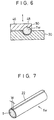
- the configuration of travel path of the paper 22 varies in the manner shown in Figs. 3 to 6. As the paper 22, along with the shredded tobacco T thereon, travels along the travel path, therefore, the tobacco T is wrapped in the paper 22, whereby a continuous tobacco rod T W is formed.
- the wrapping section 16 is provided with a lower mold 30 which is formed of an elongate plate.
- the lower mold 30 extends horizontally in the traveling direction of the paper 22 or the garniture tape 20.
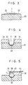
- the upper-course portion of the top face of the lower mold 30, with respect to the traveling direction of paper 22, is a flat surface, as shown in Fig. 3. Therefore, the garniture tape 20 is in sliding contact with this flat surface as it travels together with the paper 22.
- That portion of the top face of the lower mold 30 which is situated on the lower-course side of the flat surface is formed as a guide tongue (not shown).
- This guide tongue is formed of a recess which gradually converges into a traveling groove 32 (see Fig. 4) with a semicircular cross section with distance from the upper-course side, with respect to the traveling direction of the garniture tape 20.
- a pair of side guides 34 are arranged individually along the opposite side edges of the guide tongue.
- the space between facing guide surfaces 35 of the side guides 34 is also reduced so as to converge into the traveling groove 32.
- the guide surfaces 35 ascend so that the distance between them increases upward.
- the paper 22 When the paper 22, along with the shredded tobacco T, is introduced into the guide tongue and the space between the side guides 34 as the garniture tape 20 travels, both side edges of the paper 22 are lifted, as shown in Fig. 4.
- the guide tongue and the side guides 34 make the paper 22 U-shaped in cross section in a manner such that the shredded tobacco T is wrapped in the paper 22 from below.
- the U-shaped paper 22 has a pair of sides and a curved portion connecting the sides.
- the garniture tape 20 has a width substantially equal to the length of the circular arc of the traveling groove 32, and the groove 32 extends to the lower-course end of the lower mold 30.
- a first upper mold 36 is set on the top face of the lower mold 30.
- the mold 36 which is situated on the lower-course side of the side guides 34, extends along one side of the traveling groove 32.
- the first upper mold 36 has a lid portion 38 which hangs over the traveling groove 32, and an arcuate groove 40 is formed in the lower surface of the lid portion 38 so as to extend facing the traveling groove 32.
- the groove 40 has a half- funnel-shaped configuration (not shown) such that it spreads out toward the side guides 34.
- the upper-course part of the lid portion 38 of the first upper mold 36 is obliquely cut off and the lid portion 38 has an oblique end crossing the traveling groove 32.
- This oblique end constitutes a guide edge.
- the U- shaped paper 22 travels past the first upper mold 36, therefore, one side of the paper 22 is pushed into the arcuate groove 40 in a manner such that it is guided by the guide edge of the lid portion 38.
- the one side of the paper 22 is curved in the form of a circular arc such that it envelops the shredded tobacco T from above.
- the one side (not clearly shown in Fig. 5) of the paper 22 extends along the arcuate groove 40 to a position just beyond the top portion of the groove 40.
- paste applicator 42 After the one side of the paper 22 is curved in this manner, paste is applied to the other side edge of the paper 22 by means of a paste applicator 42 (see Fig. 2). More specifically, the paste applicator 42 includes an applicator disk 44, which is indicated by two-dot chain line in Fig. 5. The disk 44 is brought into rolling contact with the other side edge of the paper 22, thereby applying a predetermined amount of paste on this side edge.
- a second upper mold 46 is set on the top face of the lower mold 30 so as to be situated on the lower-course side of the first upper mold 36.
- the second upper mold 46 is continuous with the first upper mold 36. Unlike the first one, however, the second upper mold 46 extends along the other side of the traveling groove 32.
- the second upper mold 46 like the first upper mold 36, has a lid portion 48 which hangs over the traveling groove 32, and an arcuate groove 50 is formed in the lower surface of the lid portion 48 so as to extend facing the traveling groove 32.
- the groove 50 like the arcuate groove 40, has a half-funnel-shaped configuration, and the lid portion 48 has an oblique end which constitutes a guide edge.
- the guide edge of the lid portion 48 is inclined in the opposite direction to that of the lid portion 38.
- the other side of the paper 22 is pushed into the arcuate groove 50 in a manner such that it is guided by the guide edge of the lid portion 48.
- the other side of the paper 22 is curved in the form of a circular arc such that it envelops the shredded tobacco T from above.
- the other side of the paper 22 is lapped on and bonded to the previously curved one side.
- the continuous tobacco rod T W such as the one shown in Fig. 7, is discharged from between the lower mold 30 and the second upper mold 46.
- the second upper mold 46 is supported for a vertical displacement such that it approaches and leaves the lower mold 30. Accordingly, the inside diameter of a formation path for the tobacco rod T W , which is defined by the traveling groove 32 and the arcuate groove 50 of the second upper mold 46, can be varied depending on the vertical position of the mold 46. Thus, the diameter of the tobacco rod T W to be formed can be adjusted. It is to be understood that when the rod diameter is adjusted in this manner, the lap width W of the opposite sides of the paper 22, in the tobacco rod T W shown in Fig. 7, is adjusted at the same time.
- Figs. 8 and 9 show in detail supporting /adjusting mechanism for the vertical displacement of the second upper mold 46. The following is a description of the mechanism.
- the second upper mold 46 includes a pair of lugs 52, which protrude from that side face of the mold 46 on the opposite side to the lid portion 48. As shown in Fig. 9, these lugs 52 are spaced in the traveling direction of the tobacco rod T W , and are rotatably connected to their corresponding brackets 56 by means of hinge pins 54, individually. Thus, the second upper mold 46 is vertically swingable around the pins 54.
- the brackets 56 are fixedly mounted on a support base 58 of the lower mold 30.
- the base 58 is mounted on a main frame 60 of the cigarette production machine.
- a driving arm 70 is mounted on the top face of the second upper mold 46 by means of a connecting plate 68.
- the plate 68 and the arm 70 are formed integrally with each other.
- the driving arm 70 projects in the opposite direction to the lugs 52 from the second upper mold 46.
- a grip 72 is attached to the central portion of the upper surface of the driving arm 70, the distal end of which is connected to the adjusting device 73.
- the adjusting device 73 is provided with a gear housing 74 which is fixed to the main frame 60, and a reversible pulse motor 76 is mounted on the lower surface of the housing 74.
- the motor 76 has an output shaft 78 which projects into the gear housing 74, and an output gear 82 is mounted on the output shaft 78 by means of a key 80.
- a screw housing 84 is mounted on the upper surface of the gear housing 74.
- the housing 84 has an open-topped cylinder hole.
- a stepped screw shaft 86 penetrates the bottom wall of the cylinder hole of the screw housing 84.
- the screw shaft 86 has a large- and small-diameter screw portions arranged from bottom to top, and the large-diameter screw portion threadedly penetrates the bottom wall of the screw housing 84.
- the lower end of the shaft 86 projects into the gear housing 74.
- a driving gear 88 which is mounted on the lower end of the screw shaft 86, is in mesh with the output gear 82 of the pulse motor 76.
- a lift cylinder 90 is slidably fitted in the cylinder hole of the screw housing 84.
- the small-diameter screw portion of the screw shaft 86 is penetratingly screwed in the lift cylinder 90.
- a hole having a diameter larger than that of the large-diameter portion of the screw shaft 86 is formed in the bottom face of the lift cylinder 90, and an axial groove 92 is formed in the outer peripheral surface of the cylinder 90.
- a stopper key 94 which is fitted in the groove 92, is fixed to the screw housing 84.
- a projecting piece 96 is formed integrally on the upper end of the cylinder 90, which projects from the screw housing 84.
- the piece 96 which extends toward the driving arm 70 of the second upper mold 46, is fitted with a pad 98 which supports the distal end of the arm 70 from below.
- a bracket 100 is mounted on the upper end of the lift cylinder 90 so as to be situated on the opposite side thereof to the projecting piece 96.
- the lower end of clamp lever 102 is rockably set up on the bracket 100 by means of a hinge pin 104.
- the clamp lever 102 is in the form of an inverted tuning fork, and a grip 106 is attached to the upper end of the lever 102.
- a toggle link 108 is disposed in the clamp lever 102.
- the upper end of the link 108 is rockably mounted on the clamp lever 102 by means of a hinge pin 110.
- a clamp arm 112 penetrates the lower part of the clamp lever 102.
- One end of the clamp arm 112 extends toward the driving arm 70, and a setscrew 114 is screwed in the one end of the arm 112.
- the distal end portion of the driving arm 70 is held between the setscrew 114 and the pad 98 on the projecting piece 96.
- the other end portion of the clamp arm 112 which is bifurcated, holds the lower end portion of the toggle link 108 from both sides. It is bent downward from the position where it projects outside the clamp lever 102.
- the bifurcated portion of the clamp arm 112 is rockably mounted on the lower end of the toggle link 108 by means of a hinge pin 116, on the one side, and is rockably connected to a tail portion 118, which extends integrally from the bracket 100, by means of a hinge pin 120, on the other side.
- the clamp lever 102 when the clamp lever 102 is set up vertically, as shown in Fig. 8, the distal end portion of the driving arm 70 is held between the pad 98 and the setscrew 114 under a predetermined force of pressure.
- the clamp lever 102 in this state, is rocked in the direction of arrow X of Fig. 8, the clamp arm 112 also rocks in the direction of arrow X around the hinge pin 120, whereupon the driving arm 70 is allowed to be released from the hold.
- the lift cylinder 90 also ascends or descends at the same time.
- the driving arm 70 is rocked in the direction of arrow Y of Fig. 8 around the hinge pin 54 with its distal end kept between the pad 98 of the cylinder 90 and the setscrew 114 of the clamp arm 112.
- the second upper mold 46, along with the driving arm 70 also rocks in like manner, whereupon the position of mold 46 relative to the lower mold 30 is adjusted.
- a pair of dryers 122 and 124 are successively arranged on the lower-course side of the second upper mold 46. These dryers 122 and 124 are situated right over the lower mold 30. Thus, the tobacco rod T W travels right under the dryers 122 and 124 immediately after passing the second upper mold 46, whereby the paste on the lap portion of the rod T W is dried.
- the tobacco rod T W comes out from the traveling groove 32 of the lower mold 30, travels past a feed-in deflector 126, and is supplied to a cutting section 128.
- the feed-in deflector 126 serves automatically to adjust the timing for the supply of the tobacco rod T W at the start of the operation of the cigarette production machine.
- the cutting section 128 cuts the tobacco rod T W into pieces or cigarettes T S having a fixed length. Thereafter, the cigarettes T S are successively fed and guided along a rail 130, and are then supplied to the next stage by means of a kicker 132.
- a density measuring section 134 and a diameter measuring section 136 are successively arranged between the cutting section 128 and the feed-in deflector 126, the former being situated closer to the cutting section 128. As shown in Fig. 1, the density measuring section 134 is incorporated into the housing of the cutting section 128. The measuring sections 134 and 136 are used to measure the filling density of the shredded tobacco T in the tobacco rod T W and the diameter of the rod T W , respectively.
- the density measuring section 134 includes a scanning head (not shown) and a measuring circuit (not shown).
- the scanning head emits radiation toward the tobacco rod T W .
- the measuring circuit detects the radiation transmitted through the tobacco rod T W , and calculates the filling density of the shredded tobacco T in accordance with the result of the detection.
- the output of the measuring circuit is supplied to the trimming device 12, whereupon the device 12 adjusts the delivery of the shredded tobacco T onto the paper 22 on the basis of the output from the measuring circuit, that is, the tobacco filling density. More specifically, the disk 18 of the trimming device 12 moves up and down, depending on the tobacco filling density, whereby the thickness of the shredded tobacco T on the conveyor belt 10 is adjusted.
- Figs. 10, 11 and 12 show the diameter measuring section 136 in detail. The following is a description of this measuring section 136.
- the diameter measuring section 136 is provided with a housing 138.
- the housing 138 includes cover plates 140 and 142 which face feed-in deflector 126 and the density measuring section 134, respectively.
- Pipe-shaped inlet and outlet pieces 144 and 146 are attached to the cover plates 140 and 142, respectively.
- the housing 138 has a partition wall 148 therein which extends parallel to the cover plates 140 and 142, and a pipe-shaped intermediate piece 150 is penetratingly attached to the wall 148.
- the pieces 144, 150 and 146 which are arranged coaxially with one another, define the path of travel of the tobacco rod T W .
- the tobacco rod T W delivered from the feed-in deflector 126 is guided in the inlet piece 144, intermediate piece 150, and outlet piece 146 in succession as it passes through the housing 138.
- the internal passage of the inlet piece 144 is gradually spread toward its inlet port, and the upper portion of the inlet port of the piece 144 is cut aslant. Therefore, the formed tobacco rod T W can be smoothly guided into the inlet piece 144 with stability.
- the partition wall 148 divides the inside of the housing 138 into two compartments 152 and 154, front and rear with respect to the traveling direction of the tobacco rod T W .
- Sensors 156 and 158 for detecting diametrical widths of the tobacco rod T W are contained in the compartments 152 and 154, respectively.
- the sensor 156 has a case which spans the path of travel of the tobacco rod T W .
- the case includes a projector portion 160 and a receptor portion 162 which horizontally face each other across the traveling path of the tobacco rod T W .
- the projector portion 160 emits laser beams, which passes through a gap between the inlet piece 144 and the intermediate piece 150, and is received by the receptor portion 162.
- the sensor 156 measures the diametrical width of the tobacco rod T W with respect to the vertical direction, on the basis of the laser beams having reached the receptor portion 162.
- the projector portion 160 includes a semiconductor laser element 164 and a collimator lens 166 for collimating the laser beams from the semiconductor element 164 into parallel beams.
- the receptor portion 162 includes a linear photodiode array 166'.
- each photodiode of the array 166' On receiving the laser beams from the projector portion 160, each photodiode of the array 166' outputs a receptor voltage. The delivery of the output from each photodiode of the array 166' is detected by scanning for each period, and the output voltage is converted into a pulse signal.
- the resulting value indicates the number of those photodiodes which are intercepted by the tobacco rod T W .
- the vertical width of the tobacco rod T W is measured on the basis of the count value and the interval between the photodiodes.
- the pulse signals are converted into video signals as required, and the video signals are supplied to a CRT (not shown). In this case, the vertical width of the tobacco rod T W is displayed on the CRT.
- the sensor 158 which has the same construction and principle of measurement as the sensor 156, is arranged so that its projector and receptor portions 160 and 162 vertically face each other. Laser beams emitted from the projector portion 160 of the sensor 158 can pass through a gap between the intermediate piece 150 and the outlet piece 146 to reach the receptor portion 162. Thus, the sensor 158 measures the diametrical width of the tobacco rod T W with respect to the horizontal direction.
- each of the delivery passages 168 is connected to its corresponding jet 172, while the other end thereof is connected to a pneumatic pressure source by means of a supply hose 174.
- Each jet 172 opens in the outer peripheral surface of the intermediate piece 150, and its axis is directed to the projector or receptor portion 160 or 162 of the sensor 156 corresponding thereto.
- each of the delivery passages 170 is connected to its corresponding jet 176, which opens to the projector or receptor portion 160 or 162 of the sensor 158 corresponding thereto, while the other end of the passage 170 is connected to the pneumatic pressure source by means of the supply hose 174.
- An end portion (not shown) of the hose 174 is branched, and each branch end is connected to its corresponding delivery passage.
- the intermediate piece 150 is thus provided with the jets 172 and 176, compressed air can be ejected from the jets 172 and 176 toward the projector and receptor portions 160 and 162 of the sensors 156 and 158, respectively, during the operation of the production machine.
- dust or the like adhering to the projector and receptor portions 160 and 162 can be brown off to be removed.
- the measuring accuracy of the sensors 156 and 158 cannot be adversely affected by dust or the like.
- a duct hole 153 which opens into the respective bottom portions of the compartments 152 and 154, is connected to a negative pressure source (not shown) by means of a suction hose (not shown).
- the values of the diametrical widths of the tobacco rod T W measured individually by means of the sensors 156 and 158 are utilized for the drive control of the adjusting device 73 of the second upper mold 46, that is, the pulse motor 76.
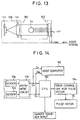
- a control circuit for the motor 76 is shown in Fig. 14.
- the sensors 156 and 158 are connected to a central processing unit or CPU 180 through an arithmetic circuit 178.
- the arithmetic circuit 178 calculates diametrical widths D H and D V of the tobacco rod T W with respect to two directions perpendicular to each other in the aforesaid manner in response to the sensor signals, that is, the pulse signals from the individual sensors, and supplies these diametrical widths D H and D V to the CPU 180.
- the diametrical widths D H and D V are supplied to a host computer 182, as well as to the CPU 180, and the computer 182 utilizes the measured diametrical widths D H and D V as data for quality control, for example.
- a target value of the diameter can be applied to the CPU 180, and the manipulated variable of the pulse motor 76, that is, a target rotational angle of the output shaft of the motor 76, is calculated in the CPU 180 in accordance with the target diameter D O and the measured diametrical widths D H and D V .
- the computed target rotational angle is supplied to a drive controller 184 of the pulse motor 76, whereupon the controller 184 controls the drive of the motor 76 so that the actual rotational angle of the motor 76 is equal to the computed target rotational angle.
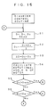
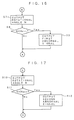
- the CPU 180 reads the diametrical widths D H , D V and D O (Step S1) and calculates an average diameter D A of the tobacco rod T W on the basis of the diametrical widths D H and D V according to the following equation (Step S2).
- D A (D H + D V )/2.
- the average diameter D A of the tobacco rod T W is a value which accurately represents the virtual diameter of the rod T W even if the travel of the rod T W is subject to any deflection, or if the profile of the rod T W is elliptic.
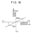
- a diameter deviation ⁇ D between the target diameter D O and the average diameter D A is calculated according to the following equation (Step S3), and a rotational angle N of the pulse motor 76 is calculated on the basis of the diameter deviation ⁇ D (Step S4).
- ⁇ D D O - D A .
- the rotational angle N of the motor corresponding to the diameter deviation ⁇ D is calculated with reference to the graph of Fig. 18 in Step S4.
- Step S5 and S6 When the rotational angle N of the motor is computed, whether or not the average diameter D A is larger than a maximum allowable diameter D MAX and whether or not the average diameter D A is smaller than a minimum allowable diameter D MIN are determined in succession in Steps S5 and S6, respectively. If the decisions in these steps are NO, then it is concluded that the computed average diameter D A is within an allowable range. In this case, therefore, the program returns to Step S1 without the drive of the pulse motor 76, and the process of Step S1 and its subsequent processes are executed repeatedly.
- Step S5 the program proceeds to Step S7 of Fig. 16, whereupon the computed rotational angle N of the pulse motor 76 is delivered from the CPU 180 to the drive controller 184. Thereupon, the controller 184 actually drives the pulse motor 76.
- the decision of Step S5 is YES, in this case, the diameter deviation ⁇ D takes a negative value, so that the rotational angle N of the motor also takes a negative value. Accordingly, the pulse motor 76 is rotated in a direction such that the second upper mold 46 is rocked toward the lower mold 30.
- the sectional area of the formation path for the tobacco rod T W which is defined by the arcuate groove 50 of the second upper mold 46 and the traveling groove 32 of the lower mold 30, is substantially diminished, so that the diameter of the tobacco rod T W formed thereafter is reduced toward the target diameter value D O .
- Step S8 After the rotational angle N of the motor is outputted, whether or not the value of the angle N is smaller than a lower limit value N MIN is determined in Step S8. If the decision in Step S8 is NO, the program returns to Step S1 of Fig. 15, whereupon the process of Step S1 and its subsequent processes are executed repeatedly. If the decision in Step S8 is YES, on the other hand, a first abnormal signal, which indicates that the diameter of the tobacco rod T W is extraordinarily large, is outputted in Step S9. Thus, if the rotational angle N is smaller than the lower limit value N MIN , then it is concluded that the diameter of the tobacco rod T W is too large or beyond the allowable limits, as seen from Fig. 18.
- the first abnormal signal should be outputted at once to inform an operator of the abnormal state.
- the program returns from Step S9 to Step S1 after the first abnormal signal is outputted.
- the program may be designed so that the CPU 180 outputs a signal for stopping the operation of the cigarette production machine after the process of Step 9 is executed and the execution of the diameter control routine is finished.
- Step S6 the program proceeds to Step S10 of Fig. 17, whereupon the computed rotational angle N is outputted. If the decision in Step S6 is YES, in this case, the diameter deviation ⁇ D takes a positive value. In order to rock the second upper mold 46 away from the lower mold 30, therefore, the pulse motor 76 is rotated in the direction opposite to the direction for the aforesaid case, whereby the diameter of the tobacco rod T W is increased toward the target diameter value D O .
- Step S11 After the rotational angle N is outputted, also in this case, whether or not the value of the angle N is larger than the upper limit value N MAX is determined in Step S11. If the decision in Step S11 is YES, a second abnormal signal, which indicates that the diameter of the tobacco rod T W is extraordinarily small, is outputted in Step S12 for the same reason as aforesaid, whereupon the program returns to Step S1. Also in this case, the CPU 180 can output the signal for stopping the operation of the cigarette production machine after the second abnormal signal is outputted.
- the pulse motor 76 is rotated in a predetermined direction, so that the position of the second upper mold 46 with respect to the lower mold 30 is adjusted. In this manner, the diameter of the tobacco rod T W can be automatically set within the allowable range.
- the diameter of the tobacco rod T W or cigarettes manufactured by means of the cigarette production machine can be stabilized. Accordingly, the width of the lap portion of the paper 22 of the tobacco rod T W can be maintained with reliability, so that the lap portion is subject to no bonding failure. If the diameter of the cigarettes is stabilized, moreover, a tip paper piece can be wound with stability, thereafter, to connect each cigarette and a filter plug.
- the present invention is not limited to the embodiment described above. If the second upper mold is supported so as to be shiftable in the vertical direction, for example, its position with respect to the lower mold 30 can be adjusted as it moves up and down.
- the sensors 156 and 158 are contained in the same housing. Alternatively, however, one of these sensors may be located on the lower-course side of the density measuring section. In short, the sensors 156 and 158 can be positioned without any special restrictions.
- the diameter of the tobacco rod T W is obtained from the simple average of the diametrical widths detected by means of the sensors 156 and 158.
- the average diameter D A may be computed by various methods. In consideration of the manufacturing processes for the tobacco rod T W , for example, the diameter of the tobacco rod T W may be obtained from a weighted average of the diametrical widths measured by the sensors.
Landscapes
- Health & Medical Sciences (AREA)
- General Health & Medical Sciences (AREA)
- Toxicology (AREA)
- Manufacturing Of Cigar And Cigarette Tobacco (AREA)
Claims (8)
- Vorrichtung zur Regelung des Durchmessers von Zigaretten, die mittels einer Zigarettenproduktionsmaschine hergestellt sind, mit:
einer unteren Form (30), welche den Laufweg von Papier (22) bestimmt, welches mit zerkleinerten Tabak (T) zugeführt wird, wobei die untere Form (30) das Papier (22) bei dessen Lauf in eine U-förmige Konfiguration bringt und das U-förmige Papier (22) zwei Seiten und einen Kurvenabschnitt aufweist, welcher die Seiten verbindet und den zerkleinerten Tabak (T) von unten umhüllt,
einer ersten oberen Form (34), welche sich direkt oberhalb der unteren Form (30) befindet, wobei die erste obere Form (34) die eine Seite des U-förmigen Papiers (22) bogenförmig ausformt und die geformte eine Seite den zerkleinerten Tabak (T) von oben umhüllt,
einer zweiten oberen Form (46), welche sich im Bezug auf den Laufweg an der zum unteren Verlauf zeigenden Seite der ersten oberen Form (34) befindet, wobei die zweite obere Form (46) die andere Seite des Papiers derart bogenförmig ausformt, daß die andere Seite bei dem Papierlauf die eine Seite überlappt, wobei die andere Seite den zerkleinerten Tabak (T) von oben umhüllt, und mit
einer Klebstoffaufbringvorrichtung (44) zum Beaufschlagen des Randes der anderen Seite des Papiers (22) mit Klebstoff, bevor das Papier die zweite obere Form (46) erreicht, sodaß die einander gegenüberliegenden Seitenränder des Papiers (22) miteinander verklebt werden, wenn die andere Seite des Papiers (22) bogenförmig ausgeformt ist, wodurch eine Tabakstange derart geformt wird, daß der zerkleinerte Tabak völlig von dem Papier umhüllt ist,
gekennzeichnet durch
eine Schneidevorrichtung (128) zum Schneiden der gebildeten Tabakstange in einzelne Zigaretten mit vorbestimmter Länge;
eine Lagervorrichtung (52, 54, 56) zur Lagerung der zweiten oberen Form (46) gerade oberhalb der unteren Form (30);
eine Einstellvorrichtung (73) zur Veränderung der Lage der zweiten oberen Form (46) in Bezug auf die untere Form (30) in Zusammenarbeit mit der Lagervorrichtung, wodurch der Durchmesser der zu bildenden Tabakstange (TW) eingestellt wird;
eine Meßvorrichtung (156, 158), welche ein Paar an optischen Sensoren (156, 158) zur Erfassung der Durchmesserbreite (DV, DH) der Tabakstange (TW) oder der Zigaretten bezüglich zweier zueinander senkrechten Richtungen und zur Abgabe der Meßresultate enthält; und durch eine Regelungsvorrichtung (180, 184) zur Regelung der Einstellvorrichtung (73) in Übereinstimmung mit den Meßresultaten derart, daß die Durchmesser der zu bildenden Tabakstange (TW) innerhalb eines erlaubten Bereiches liegen,
wobei zu jedem der Sensoren (156, 158) ein Projektionsabschnitt (160) zur Abstrahlung von Laserstrahlen auf die Tabakstange (TW), ein Empfangsabschnitt (162) zum Empfang der von dem Projektionsabschnitt (160) ausgehenden Laserstrahlen und zum Abgeben eines Erfassungssignals, welches demjenigen Anteil der Laserstrahlen entspricht, der durch die Tabakstange (TW) abgefangen wird sowie eine arithmetische Einheit (178) zur Berechnung der Durchmesserbreiten der Tabakstange (TW) in Übereinstimmung mit dem von dem Empfangsabschnitt (162) abgegebenen Erfassungssignal gehören,
wobei die Meßvorrichtung ferner ein Gehäuse (138), welches das Sensorpaar (156, 158) enthält und den Durchgang der Tabakstange (TW) erlaubt sowie eine Halterung (144, 146, 159) in dem Gehäuse (138) zur
Führung der Tabakstange (TW) beim Durchgang aufweist, wobei zu dem Halter ein Einlaßstück (144) zum Einführen der Tabakstange (TW) in das Gehäuse (138), ein Auslaßstück (146) zum Abführen der Tabakstange (TW) von dem Gehäuse (138) sowie ein Zwischenstück (150) gehören, welches sich zwischen dem Einlaßstück (144) und dem Auslaßstück (146) befindet, wobei jedes der Stücke aus einem Röhrenelement zum Führen der Tabakstange (TW) gebildet ist und sich zueinander auf derselben Achse liegend befinden, wobei sich der Projektionsabschnitt und der Empfangsabschnitt (160, 162) eines Sensors des Sensorpaares einander über einen Spalt gegenüber liegen, welcher sich zwischen dem Einlaßstück (144) und dem Zwischenstück (150) befindet, und wobei der Projektionsabschnitt und der Empfangsabschnitt (160, 162) des anderen Sensors sich einander über einen Spalt gegenüber liegen, welcher sich zwischen dem Zwischenstück (150) und dem Auslaßstück (146) befindet. - Gerät nach Anspruch 1
dadurch gekennzeichnet, daß
die Meßvorrichtung ferner eine Säuberungsvorrichtung zum Säubern der jeweiligen Projektions- und Empfangsabschnitte (160, 162) der Sensoren (156, 158) durch Blasen von komprimierter Luft gegen den Projektions- und Empfangsabschnitt enthält. - Gerät nach Anspruch 2
dadurch gekennzeichnet, daß
die Säuberungsvorrichtung Düsen (172, 176) in dem Zwischenstück (150) enthält, durch welche die komprimierte Luft hin zu den jeweiligen Projektions- und Empfangsabschnitten (160, 162) der Sensoren (156, 158) ausgestoßen wird. - Gerät nach Anspruch 3
dadurch gekennzeichnet, daß
die Säuberungsvorrichtung ferner eine Lüftungsbohrung (153) enthält, durch welche die Luft in dem Gehäuse (138) abgegeben wird. - Gerät nach Anspruch 1
dadurch gekennzeichnet, daß
die Regelungsvorrichtung eine erste Stufe zur Berechnung des durchschnittlichen Durchmessers (DA) der Tabakstange (TW) in Übereinstimmung mit den Ausgangssignalen der Sensoren (156, 158), eine zweite Stufe zur Berechnung der Abweichung (ΔD) zwischen dem berechneten Durchschnittsdurchmesser (DA) und einem vorher festgelegten Solldurchmesser der Tabakstange (TW), eine dritte Stufe zur Berechnung der Stellgröße der Einstellvorrichtung (73) in Übereinstimmung mit der berechneten Abweichung und eine vierte Stufe zum Zuführen der in der dritten Stufe berechneten Stellgröße zu der Einstellvorrichtung (73) aufweist, wenn der berechnete Durchschnittsdurchmesser (DA) von dem erlaubten Bereich abweicht. - Gerät nach Anspruch 5
dadurch gekennzeichnet, daß
die Regelungsvorrichtung ferner eine fünfte Stufe zur Abgabe eines anormalen bzw. einen anormalen Zustand anzeigenden Signals enthält, wenn die in der dritten Stufe berechnete Stellgröße größer ist als ein vorbestimmter Wert. - Gerät nach Anspruch 1
dadurch gekennzeichnet, daß
die Lagervorrichtung
ein Scharnier (54) enthält, welches vertikal schwingbar einen Seitenrand der zweiten oberen Form (46) auf einer Seite einer unteren Form lagert; und daß die Einstellvorrichtung eine abgestufte Schraubenwelle (86), welche einen Schraubenabschnitt mit großem Durchmesser und einen Schraubenabschnitt mit kleinem Durchmesser an dessen unteren und oberen Endabschnitten aufweist, wobei der Schraubenabschnitt mit großem Durchmesser in ein stationäres Schraubengehäuse (84) eingeschraubt ist, der Schraubenabschnitt mit kleinem Durchmesser von dem stationären Schraubengehäuse (84) hervorragt, einen Hebezylinder (90), der auf den Schraubenabschnitt der abgestuften Schraubenwelle (86) mit schmalem Durchmesser angebracht ist und lediglich in Vertikalrichtung bewegbar ist, wobei der Hebezylinder (90) eine Druckunterlage (98) aufweist, die einen zweiten Seitenrand der zweiten oberen Form (46) von unten berührt, eine Antriebsvorrichtung (76) zum Drehen der abgestuften Schraubenwelle (86) nach vorwärts und rückwärts und eine Haltevorrichtung (112, 114) zum Halten des zweiten Seitenrandes der zweiten oberen Form (46) und der Druckunterlage (98) des Hebezylinders (90) besitzt. - Gerät nach Anspruch 7
dadurch gekennzeichnet, daß
die Regelungsvorrichtung einen Regler (184) enthält, welcher funktionell jeweils mit der Antriebsvorrichtung (76) und den Sensoren (156, 158), zur Erzeugung eines Einstellsignals in Übereinstimmung mit den erfaßten Durchmesserbreiten der Tabakstange und zum Veranlassen der Antriebsvorrichtung (76) sich wahlweise in Vorwärts- und Rückwärtsrichtung in Abhängigkeit von dem Einstellsignal zu drehen, verbunden ist.
Applications Claiming Priority (2)
| Application Number | Priority Date | Filing Date | Title |
|---|---|---|---|
| JP02655092A JP3273802B2 (ja) | 1992-02-13 | 1992-02-13 | シガレット製造機における巻たばこの巻径制御装置 |
| JP26550/92 | 1992-02-13 |
Publications (2)
| Publication Number | Publication Date |
|---|---|
| EP0555875A1 EP0555875A1 (de) | 1993-08-18 |
| EP0555875B1 true EP0555875B1 (de) | 1995-09-20 |
Family
ID=12196631
Family Applications (1)
| Application Number | Title | Priority Date | Filing Date |
|---|---|---|---|
| EP93102272A Expired - Lifetime EP0555875B1 (de) | 1992-02-13 | 1993-02-12 | Vorrichtung zur Regulierung des Durchmessers von Zigaretten, die mittels einer Zigaretten-Herstellungsmaschine hergestellt werden |
Country Status (4)
| Country | Link |
|---|---|
| US (1) | US5370137A (de) |
| EP (1) | EP0555875B1 (de) |
| JP (1) | JP3273802B2 (de) |
| DE (1) | DE69300494T2 (de) |
Cited By (1)
| Publication number | Priority date | Publication date | Assignee | Title |
|---|---|---|---|---|
| EP3853594B1 (de) * | 2018-09-21 | 2024-02-21 | G.D S.p.A. | Elektromagnetischer detektor zur erfassung von eigenschaften von produkten der tabakverarbeitenden industrie |
Families Citing this family (14)
| Publication number | Priority date | Publication date | Assignee | Title |
|---|---|---|---|---|
| DE19523273A1 (de) * | 1995-06-27 | 1997-01-09 | Hauni Maschinenbau Ag | Verfahren und Anordnung zum Messen des Durchmessers eines stabförmigen Artikels der tabakverarbeitenden Industrie |
| IT1295207B1 (it) * | 1997-10-01 | 1999-05-04 | Gd Spa | Unita' per il rilevamento delle dimensioni trasversali di articoli a forma di barretta. |
| JP3248682B2 (ja) | 1998-01-12 | 2002-01-21 | 日本たばこ産業株式会社 | シガレット製造機の刻みたばこ層圧縮成形装置 |
| ES2264459T3 (es) * | 2002-09-11 | 2007-01-01 | Hauni Maschinenbau Ag | Procedimiento y dispositivo para medir la longitud y el diametro de barras de filtro. |
| DE10323152A1 (de) * | 2003-05-22 | 2004-12-16 | Hauni Maschinenbau Ag | Vorrichtung zum Messen des Durchmessers eines stabförmigen Gegenstandes insbesondere der Tabak verarbeitenden Industrie |
| UA91206C2 (uk) * | 2004-12-15 | 2010-07-12 | Джапан Тобакко Інк. | Пристрій для виготовлення стрижнеподібних курильних виробів |
| ITBO20080031A1 (it) * | 2008-01-21 | 2009-07-22 | Gd Spa | Unita per il controllo ottico di articoli di forma allungata del settore del tabacco. |
| CN102621901B (zh) * | 2012-02-17 | 2013-10-02 | 江西中烟工业有限责任公司南昌卷烟厂 | 一种用于卷烟机节电控制装置 |
| CN103126064A (zh) * | 2013-02-28 | 2013-06-05 | 湖北中烟工业有限责任公司 | 提高烟支质量的烟枪 |
| CN107920583B (zh) * | 2015-10-08 | 2021-05-11 | 菲利普莫里斯生产公司 | 一种用于调整伸长条的直径的方法 |
| WO2017114871A1 (en) * | 2015-12-30 | 2017-07-06 | Philip Morris Products S.A. | Filter manufacturing apparatus |
| CN106501458B (zh) * | 2016-11-18 | 2018-10-16 | 中国电子科技集团公司第四十一研究所 | 一种烟支水平扶正装置 |
| US11690397B2 (en) * | 2018-08-03 | 2023-07-04 | Philip Morris Products S.A. | Reconfigurable wrapping mechanism |
| WO2023280525A1 (en) * | 2021-07-09 | 2023-01-12 | Philip Morris Products S.A. | Gathering assembly |
Family Cites Families (10)
| Publication number | Priority date | Publication date | Assignee | Title |
|---|---|---|---|---|
| GB448620A (en) * | 1934-12-06 | 1936-06-08 | Arthur Podmore | Improvements in and relating to the manufacture of cigarettes |
| US4027137A (en) * | 1975-09-17 | 1977-05-31 | International Business Machines Corporation | Laser drilling nozzle |
| US4164229A (en) * | 1977-03-18 | 1979-08-14 | Hurt James S | Portable cigarette making machine |
| DE2836030C2 (de) * | 1977-08-24 | 1987-01-29 | Molins Ltd., London | Strangherstellungsmaschine für die tabakverarbeitende Industrie |
| IT1186557B (it) * | 1985-01-23 | 1987-12-04 | Gd Spa | Dispositivo di controllo e di correzione delle dimensione trasversali di prodotti a forma di barretta,in particolare per macchine confezionatrici di prodotti da fumo |
| US4986285A (en) * | 1986-03-06 | 1991-01-22 | Korber Ag | Method and apparatus for ascertaining the density of wrapped tobacco fillers and the like |
| DE3801115C2 (de) * | 1987-01-31 | 1996-10-17 | Hauni Werke Koerber & Co Kg | Verfahren und Vorrichtung zum Bestimmen der Dichte eines Faserstrangs der tabakverarbeitenden Industrie |
| JPS643504A (en) * | 1987-06-05 | 1989-01-09 | Seraniizu Fiber Zu Inc | Mounting construction for apparatus which measures diameter of cylindrical object such as tobacco filter rod on line |
| NL8900787A (nl) * | 1989-03-31 | 1990-10-16 | Turmac Tobacco Co Nv | Werkwijze en inrichting voor het vervaardigen van een door een papierstrook omsloten strang uit tabak of dergelijke, alsmede sigaret vervaardigd onder toepassing van deze werkwijze. |
| JP3071537B2 (ja) | 1991-03-29 | 2000-07-31 | 日本たばこ産業株式会社 | 棒状物品の太さ計測装置 |
-
1992
- 1992-02-13 JP JP02655092A patent/JP3273802B2/ja not_active Expired - Fee Related
-
1993
- 1993-02-10 US US08/015,859 patent/US5370137A/en not_active Expired - Fee Related
- 1993-02-12 EP EP93102272A patent/EP0555875B1/de not_active Expired - Lifetime
- 1993-02-12 DE DE69300494T patent/DE69300494T2/de not_active Expired - Fee Related
Cited By (1)
| Publication number | Priority date | Publication date | Assignee | Title |
|---|---|---|---|---|
| EP3853594B1 (de) * | 2018-09-21 | 2024-02-21 | G.D S.p.A. | Elektromagnetischer detektor zur erfassung von eigenschaften von produkten der tabakverarbeitenden industrie |
Also Published As
| Publication number | Publication date |
|---|---|
| US5370137A (en) | 1994-12-06 |
| DE69300494T2 (de) | 1996-02-29 |
| EP0555875A1 (de) | 1993-08-18 |
| DE69300494D1 (de) | 1995-10-26 |
| JP3273802B2 (ja) | 2002-04-15 |
| JPH05219930A (ja) | 1993-08-31 |
Similar Documents
| Publication | Publication Date | Title |
|---|---|---|
| US5370137A (en) | Apparatus for controlling the diameter of cigarettes to be manufactured by means of a cigarette production machine | |
| US5116298A (en) | Control process and apparatus for the production of cigarette filters | |
| US4721119A (en) | Rod making machine with means for adjusting the position of wrapping material | |
| US4511420A (en) | Continuous rod manufacture | |
| EP1500336A1 (de) | Drucker einer maschine zur herstellung von zigaretten | |
| JPH11266850A (ja) | 挿入物を備えているシガレットを製造するための方法およびこの方法を実施するための装置 | |
| JP3372193B2 (ja) | シガレット製造装置 | |
| RU2186512C2 (ru) | Добавление модифицирующих дым агентов в стержни курительного материала | |
| US7665468B2 (en) | Cigarette making machine and method | |
| US4974443A (en) | Method of and apparatus for ascertaining the hardness of cigarettes and the like | |
| US4555011A (en) | Conveying rod-like articles | |
| JP3274882B2 (ja) | シガレット製造機のたばこロッド走行案内装置 | |
| JPS63209575A (ja) | たばこから連続体を形成するための方法および装置 | |
| JPS61205471A (ja) | 紙巻煙草製造機械におけるストリツプ紙の供給方法及び装置 | |
| JPS61216672A (ja) | たばこのような喫煙可能な繊維から連続体を形成するための装置 | |
| JP2003259852A (ja) | たばこ加工産業におけるシガレット連続体或いは棒状製品の直径を測定するための方法および装置 | |
| KR20030017975A (ko) | 고무 재료에 매립되어 있는 코드 스트립을 서로접속시키는 접속 장치 | |
| JPH0824558B2 (ja) | フィルタロッドを製造するための方法および装置 | |
| ITBO970592A1 (it) | Unita' per il rilevamento delle dimensioni trasversali di articoli a forma di barretta. | |
| JPS63304971A (ja) | たばこ加工産業における繊維連続体を作るための方法および装置 | |
| EP0556804B1 (de) | Vorrichtung zur Regulierung der Füllmenge geschnitteten Tabaks in Zigaretten | |
| JP3171842B2 (ja) | 棒状巻包物の外周制御方法及び装置 | |
| JPH05227938A (ja) | シガレット製造機における巻たばこの印刷濃度調整装置 | |
| GB2247952A (en) | Apparatus for conveying a flat article | |
| US20040216755A1 (en) | Method of and apparatus for ascertaining parameters of cigarette paper and the like |
Legal Events
| Date | Code | Title | Description |
|---|---|---|---|
| PUAI | Public reference made under article 153(3) epc to a published international application that has entered the european phase |
Free format text: ORIGINAL CODE: 0009012 |
|
| AK | Designated contracting states |
Kind code of ref document: A1 Designated state(s): DE GB IT |
|
| 17P | Request for examination filed |
Effective date: 19930903 |
|
| 17Q | First examination report despatched |
Effective date: 19940418 |
|
| GRAA | (expected) grant |
Free format text: ORIGINAL CODE: 0009210 |
|
| AK | Designated contracting states |
Kind code of ref document: B1 Designated state(s): DE GB IT |
|
| ITF | It: translation for a ep patent filed | ||
| REF | Corresponds to: |
Ref document number: 69300494 Country of ref document: DE Date of ref document: 19951026 |
|
| PLBE | No opposition filed within time limit |
Free format text: ORIGINAL CODE: 0009261 |
|
| STAA | Information on the status of an ep patent application or granted ep patent |
Free format text: STATUS: NO OPPOSITION FILED WITHIN TIME LIMIT |
|
| 26N | No opposition filed | ||
| REG | Reference to a national code |
Ref country code: GB Ref legal event code: IF02 |
|
| PGFP | Annual fee paid to national office [announced via postgrant information from national office to epo] |
Ref country code: GB Payment date: 20050209 Year of fee payment: 13 |
|
| PGFP | Annual fee paid to national office [announced via postgrant information from national office to epo] |
Ref country code: DE Payment date: 20050228 Year of fee payment: 13 |
|
| PG25 | Lapsed in a contracting state [announced via postgrant information from national office to epo] |
Ref country code: GB Free format text: LAPSE BECAUSE OF NON-PAYMENT OF DUE FEES Effective date: 20060212 |
|
| PGFP | Annual fee paid to national office [announced via postgrant information from national office to epo] |
Ref country code: IT Payment date: 20060228 Year of fee payment: 14 |
|
| PG25 | Lapsed in a contracting state [announced via postgrant information from national office to epo] |
Ref country code: DE Free format text: LAPSE BECAUSE OF NON-PAYMENT OF DUE FEES Effective date: 20060901 |
|
| GBPC | Gb: european patent ceased through non-payment of renewal fee |
Effective date: 20060212 |
|
| PG25 | Lapsed in a contracting state [announced via postgrant information from national office to epo] |
Ref country code: IT Free format text: LAPSE BECAUSE OF NON-PAYMENT OF DUE FEES Effective date: 20070212 |