EP0555965A2 - Système avec piège à gaz contrôlé - Google Patents
Système avec piège à gaz contrôlé Download PDFInfo
- Publication number
- EP0555965A2 EP0555965A2 EP93300478A EP93300478A EP0555965A2 EP 0555965 A2 EP0555965 A2 EP 0555965A2 EP 93300478 A EP93300478 A EP 93300478A EP 93300478 A EP93300478 A EP 93300478A EP 0555965 A2 EP0555965 A2 EP 0555965A2
- Authority
- EP
- European Patent Office
- Prior art keywords
- mud
- gas
- trap
- housing
- gas trap
- Prior art date
- Legal status (The legal status is an assumption and is not a legal conclusion. Google has not performed a legal analysis and makes no representation as to the accuracy of the status listed.)
- Granted
Links
Images

Classifications
-
- E—FIXED CONSTRUCTIONS
- E21—EARTH OR ROCK DRILLING; MINING
- E21B—EARTH OR ROCK DRILLING; OBTAINING OIL, GAS, WATER, SOLUBLE OR MELTABLE MATERIALS OR A SLURRY OF MINERALS FROM WELLS
- E21B49/00—Testing the nature of borehole walls; Formation testing; Methods or apparatus for obtaining samples of soil or well fluids, specially adapted to earth drilling or wells
- E21B49/005—Testing the nature of borehole walls or the formation by using drilling mud or cutting data
-
- B—PERFORMING OPERATIONS; TRANSPORTING
- B01—PHYSICAL OR CHEMICAL PROCESSES OR APPARATUS IN GENERAL
- B01D—SEPARATION
- B01D19/00—Degasification of liquids
- B01D19/0042—Degasification of liquids modifying the liquid flow
- B01D19/0052—Degasification of liquids modifying the liquid flow in rotating vessels, vessels containing movable parts or in which centrifugal movement is caused
-
- E—FIXED CONSTRUCTIONS
- E21—EARTH OR ROCK DRILLING; MINING
- E21B—EARTH OR ROCK DRILLING; OBTAINING OIL, GAS, WATER, SOLUBLE OR MELTABLE MATERIALS OR A SLURRY OF MINERALS FROM WELLS
- E21B21/00—Methods or apparatus for flushing boreholes, e.g. by use of exhaust air from motor
- E21B21/06—Arrangements for treating drilling fluids outside the borehole
- E21B21/063—Arrangements for treating drilling fluids outside the borehole by separating components
- E21B21/067—Separating gases from drilling fluids
Definitions
- the present invention relates to a method and apparatus for uniformly and continuously drawing samples of gas entrained in a liquid containing a high percentage of solids. More particularly, the present invention relates to a method and apparatus for obtaining samples of gases contained in drilling mud coming to the surface from an oil well drilling operation.
- drilling mud a special fluid, termed "drilling mud", which is pumped down the drill string to circulate from the drilling head and carry upward to the surface the debris created by the drilling operation.
- drilling mud a special fluid
- a gas-containing strata When a gas-containing strata is encountered by the drilling operation, a certain amount of the gas from the strata will be entrained in the drilling mud and thus be carried to the surface. Extracting these gases from the drilling mud allows determination of the presence of hydrocarbons and an estimate of the quantity of hydrocarbon being encountered. Analysis of the recovered gas can be used to make a determination as to the desirability of recovering the gas or oil from the particular strata.
- This practice is generally categorized as "mud logging”.
- the known devices for accomplishing mud logging separate the gas from the fluid by an agitation or vibrating process.
- the gas i.e. hydrocarbon
- samples are collected in a gas trap during this operation.
- Gas traps of several different designs are currently used in the mud logging industry in order to extract light hydrocarbon gases from the return flow line mud for measurement. The purpose of this measurement is twofold: (1) to provide warning of dangerous underbalanced drilling conditions indicated by increased gas returns; and (2) to evaluate the formation being drilled for hydrocarbon productivity.
- the amount of air dilution cannot be measured accurately in the current traps because of air and gas leaks through the fluid exhaust port, which is generally open to the air outside the trap, and leakage around the motor shaft stirrer bar.
- gas traps operate by diverting a portion of the return mud through an enclosed volume which provides some mechanism for gas release within that volume.
- the mechanism may be passive, such as a mud-spreading plate, or may contain some sort of mechanical agitator to maximize the mud/air contact.
- the evolved gas is conveyed to the analytical equipment by means of suction applied to a gas phase sample line attached to the trap body. Due to the need to provide continuously updated gas readings, mud residence time within the trap is normally so short that only a fraction of the gas is released. For quantitative operation, the trap design must therefore be such that the observed gas in the sample stream can be easily related to the actual gas content of the return mud.
- mud phase entry and exit flows to permit continuous sampling of fresh mud, gas phase sampling flow, and gas phase vent flow whose direction and rate is determined by the difference in gas evolution and gas sampling rates.
- these flows should be discreet and accessible to measurement by the operator.
- Of particular importance is the avoidance of uncontrolled external air and evolved gas mixing due to poor design of the trap vent flow, a failing encountered in several commonly used trap designs.
- the present invention overcomes the difficulties of the prior art by providing a gas trap which eliminates problems with existing trap designs and provides an accurate and reliable tool for measuring mud gas.
- Quantitative operation is provided by inclusion of a discrete air vent line, whose far end is in gas-free air, and by elimination of uncontrolled gas phase mixing at the mud exit port and the agitator shaft feed-through.
- the mud exit port is sealed to gas exchange by means of a down-tube directing the exiting mud to below the external mud surface.
- the down-tube design is such that spent mud is directed away from the mud entry port to insure that fresh mud is continuously sampled.
- the invention provides immersion level insensitivity by means of an agitator design used in combination with a mud containment ring within the trap body.
- trap operation is made more reliable and maintenance free by means of splash protection baffles which minimize the chance for mud plugging of the vent and sampling lines.
- the present invention is a gas trap which is compact, easily installed, has low maintenance requirements, provides quantitative gas recovery and is insensitive to immersion level changes encountered during normal drilling operations.
- the present invention is of the enclosed agitator type.
- the present invention is of maximum simplicity and economy of design in that a number of important functions are simultaneously provided by the agitator, including, but not limited to: (1) the trap body is configured such that the agitator pumps mud through the trap by centrifugal action so that no external mud pump is required; (2) the agitator provides vigorous mud/gas phase mixing within the trap body to release the gas entrained in the mud; (3) the agitator motion causes rapid gas phase mixing of evolved gas and vent air so that the sample line gas is representative of the current gas content of the mud; (4) the agitator induced fluid flow acts to clear the trap body of mud cuttings with little operator maintenance needed; (5) the agitator design gives constant gas evolution for a given amount of gas in the mud, even with changes in the immersion level of the trap mud entry port in the
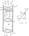
- the subject gas trap 10 has a cylindrical trap body 12 closed at its upper end by plate 14 and at its lower end by a plate 16 having a central annular aperture 18 which is coaxial with the housing 12.
- a plate 16 having a central annular aperture 18 which is coaxial with the housing 12.
- an annular plate 20 having a central annular opening 22 which also is coaxial with the housing 12. Plates 16 and 20 define a mixing chamber 24 therebetween.
- a constant speed motor 26 is mounted coaxially on top plate 14 by means of spacers 28.
- a shaft 30 of the motor extends through gas tight feed-through 32 into the interior of the housing 12.
- a sample line 34 is connected to port 36 and a vent line 38 is connected to port 40. These ports have been shown in the top plate 14 but need not be so located.
- An agitator 42 is connected to the bottom of the shaft 30 and lies in the mixing chamber 24 defined between the plates 16 and 20.
- the embodiment of the agitator 42 shown in Figure 1 consists of a plurality of legs 44, 46, 48 fixed at their upper ends to shaft 30 and downwardly diverting so that, in revolution, they define a conical configuration.
- a mud exit port 50 is formed in the housing 12 above the level of the intermediate plate 20.
- An annular plate 52 is fixed in the housing above the mud exit port 50 to define a splash chamber 54 between plates 20 and 52.
- the annular plate 52 has a central aperture 56 which is coaxial with housing 12 and through which shaft 30 passes.
- a splash disc 58 is mounted on the shaft 30 below and immediately adjacent to annular plate 52.
- the splash disc 58 has a plurality of integral, radially directed gas mixing vanes 60 directed towards plate 52.
- a mud exhaust line 62 is connected to the mud exit port 50 and is here shown with a first downwardly bent elbow 64, a straight intermediate portion 66, a second bent elbow 68 and a short straight extension 70.
- the purpose of the mud exhaust line is two fold. First, by returning the mud to below the surface of the mud 72 in tank 74, it insures that there will be no uncontrolled dilution of the evolved gas within the housing 12 from outside air. Second, it insures that the spent mud exiting the trap 10 will be returned below the level of the mud at a point remote from and directed away from the entry of the mud to the subject gas trap through aperture 18 thereby assuring that the trap 10 will be constantly working on a fresh mud supply.
- the lower and intermediate plates 16, 20 limit mud flow and also provide a more discreet air/mud mixing volume.
- the trap 10 is mounted in a conventional mud tank 74 by known means 76 such that the external mud level 72 is about midway between the lower and intermediate plates 16,20 when the rig pumps (not shown) are at their normal operating rate.
- This mounting of the subject trap 10 can be achieved by any of a number of known fixed and adjustable mounting means which have been schematically shown.
- the length of the straight portion 66 of the mud exhaust line 62 is such that the diversion elbow 68 is located below the mud level, and preferably below the lower plate 16 as shown.
- the elbow 68 is spaced from and directed away from the intake aperture 18 of the trap.
- the trap orientation in the tank is such that the mud exit port 50 is downstream of the mud flowing past the trap.
- the mud enters the trap 10 via the opening 18 in the lower plate 16 at the trap bottom and is vigorously mixed by the agitator 42 in the mixing chamber 24 in order to release entrained gas.
- the centrifugal agitation motion causes the mud to exit the mixing chamber 24 through the opening 22 in the intermediate plate 20 and to be returned to the mud tank via mud exit port 50 and exhaust line 62.
- the action of the agitator 42 also causes rapid gas phase mixing of air admitted via the vent port 36 with gases released from the mud.
- the purpose of the mud exit line assembly 62 and the sealed feed through 32 is to provide quantitative operation by eliminating mixing of the evolved gas with external air. Such mixing would act to dilute the evolved gas in an unpredictable fashion, particularly when the trap is subject to variable wind conditions.
- the diversion elbow 68 on the mud exit line assembly 62 assures that the spent mud, that is the mud having at least a portion of the entrained gas removed therefrom, is not recirculated through the trap body which, of course, would cause an erroneous reading by diluting the incoming drilling mud with processed mud from which the gas had been removed.
- the air vent 40 is present for gas phase pressure equilibration and allows the suction rate of the sample line to be set at any desired level regardless of the actual gas evolution rate from the trap.
- the exact location of the vent port 40 in the trap body is not critical.
- the primary consideration for the location of the suction and vent ports is that there be good mixing of the air with the evolved gas and avoidance of plugging of the ports due to mud splashing. This latter feature is accomplished in the upper part of the trap gas sample mixing chamber 54 by fixed annular ring 52 in combination with splash disc 58 and vanes 60 mounted on the agitator shaft 30.
- the vent line diameter and its length are such that the end of the line away from the trap is in essentially gas free air and the line pressure drop is small at the suction flow rates of interest.
- the operator will normally use a suction rate in excess of the largest total evolution rate whose precise measurement is of interest.
- the suction rate exceeds the suction rate, the trap is saturated in that gas is lost via the vent and the above equation no longer applies.
- a minor portion of the evolved gas may be lost via the mud exit port due to agitator created bubbles. This loss effectively increases the suction rate and may be accounted for by adding a correction term to the value for S in the equation.
- the three pronged agitator detailed in Figures 1 and 3 and the intermediate plate 20 act to stabilize the gas evolution rate against changes in trap immersion level in the mud.
- the overall trap mud flow tends to increase with the immersion level.
- the agitator is designed to gradually lose its mud/air mixing effectiveness as it is more deeply submerged in the mud. As a result, the net evolution rate which is given by product of mud flow rate and the efficiency of mud gas removal tends to remain constant.
Landscapes
- Engineering & Computer Science (AREA)
- Geology (AREA)
- Life Sciences & Earth Sciences (AREA)
- Mining & Mineral Resources (AREA)
- Environmental & Geological Engineering (AREA)
- Fluid Mechanics (AREA)
- Physics & Mathematics (AREA)
- General Life Sciences & Earth Sciences (AREA)
- Geochemistry & Mineralogy (AREA)
- Chemical & Material Sciences (AREA)
- Chemical Kinetics & Catalysis (AREA)
- Mechanical Engineering (AREA)
- Sampling And Sample Adjustment (AREA)
Applications Claiming Priority (2)
| Application Number | Priority Date | Filing Date | Title |
|---|---|---|---|
| US835874 | 1992-02-14 | ||
| US07/835,874 US5199509A (en) | 1992-02-14 | 1992-02-14 | Controlled gas trap system |
Publications (3)
| Publication Number | Publication Date |
|---|---|
| EP0555965A2 true EP0555965A2 (fr) | 1993-08-18 |
| EP0555965A3 EP0555965A3 (en) | 1993-11-24 |
| EP0555965B1 EP0555965B1 (fr) | 1996-01-03 |
Family
ID=25270680
Family Applications (1)
| Application Number | Title | Priority Date | Filing Date |
|---|---|---|---|
| EP93300478A Expired - Lifetime EP0555965B1 (fr) | 1992-02-14 | 1993-01-22 | Système avec piège à gaz contrÔlé |
Country Status (7)
| Country | Link |
|---|---|
| US (1) | US5199509A (fr) |
| EP (1) | EP0555965B1 (fr) |
| JP (1) | JPH0611425A (fr) |
| BR (1) | BR9300570A (fr) |
| CA (1) | CA2086876A1 (fr) |
| MX (1) | MX9300760A (fr) |
| NO (1) | NO930480L (fr) |
Cited By (2)
| Publication number | Priority date | Publication date | Assignee | Title |
|---|---|---|---|---|
| FR2829945A1 (fr) * | 2001-09-25 | 2003-03-28 | Geoservices | Module d'extraction de gaz d'un liquide de sous-sol et installation munie du module |
| WO2017003419A1 (fr) * | 2015-06-29 | 2017-01-05 | Halliburton Energy Services, Inc. | Procédés pour la détermination de l'efficacité de l'extraction de gaz à partir d'un fluide de forage |
Families Citing this family (54)
| Publication number | Priority date | Publication date | Assignee | Title |
|---|---|---|---|---|
| US5648603A (en) * | 1995-12-04 | 1997-07-15 | Texaco Inc. | Method and apparatus for stabilizing a quantitative measurement gas trap used in a drilling operation |
| US5617727A (en) * | 1996-05-24 | 1997-04-08 | Richard R. Zito R & D Corp. | Controlled multiple storage vessel gas trap |
| CA2270833C (fr) * | 1999-04-30 | 2009-11-10 | Kosta Zamfes | Piege a gaz pour boue de forage |
| FR2815074B1 (fr) * | 2000-10-10 | 2002-12-06 | Inst Francais Du Petrole | Methode d'analyse et de mesures chimique et isotopique sur des constituants transportes par un fluide de forage |
| US6666099B2 (en) | 2001-06-05 | 2003-12-23 | Pason Systems Corp. | Apparatus to recover sample gases from fluids |
| FR2856609B1 (fr) * | 2003-06-27 | 2006-12-15 | Geolog Spa | Systeme de degazage d'un milieu liquide et d'analyse des gaz contenus dans le milieu liquide |
| US7421881B2 (en) * | 2003-10-27 | 2008-09-09 | Baker Hughes Incorporated | Method and system for degassing a fluid |
| FR2875712B1 (fr) * | 2004-09-30 | 2006-12-01 | Geoservices | Dispositif d'extraction d'au moins un gaz contenu dans une boue de forage et ensemble d'analyse associe |
| US7438128B2 (en) * | 2005-05-04 | 2008-10-21 | Halliburton Energy Services, Inc. | Identifying zones of origin of annular gas pressure |
| US20060254421A1 (en) * | 2005-05-12 | 2006-11-16 | Epoch Well Services, Inc. | Gas trap for drilling mud |
| US20090007635A1 (en) * | 2007-06-22 | 2009-01-08 | Konstandinos Zamfes | Floating Bubble Jar Gas Dryer for Mud Gas Analyzer |
| US7794527B2 (en) * | 2007-09-26 | 2010-09-14 | Fluid Inclusion Technologies, Inc. | Variable position gas trap |
| US8011238B2 (en) * | 2008-10-09 | 2011-09-06 | Chevron U.S.A. Inc. | Method for correcting the measured concentrations of gas components in drilling mud |
| US8467050B2 (en) * | 2009-06-11 | 2013-06-18 | M-I Llc | Apparatus and method for metering flare gas |
| US7844400B1 (en) * | 2009-11-10 | 2010-11-30 | Selman and Associates, Ltd. | System for sampling fluid from a well with a gas trap |
| US7957903B1 (en) * | 2009-11-10 | 2011-06-07 | Selman and Associates, Ltd. | Gas trap for sampling fluid from a well |
| US8632625B2 (en) | 2010-06-17 | 2014-01-21 | Pason Systems Corporation | Method and apparatus for liberating gases from drilling fluid |
| US8584518B2 (en) | 2010-06-30 | 2013-11-19 | Rigsat Communications Inc. | Gas trap for drilling mud having quick-release separable lower section |
| US8463550B1 (en) | 2010-09-10 | 2013-06-11 | Selman and Associates, Ltd. | System for geosteering directional drilling apparatus |
| US8463549B1 (en) | 2010-09-10 | 2013-06-11 | Selman and Associates, Ltd. | Method for geosteering directional drilling apparatus |
| US9528372B2 (en) | 2010-09-10 | 2016-12-27 | Selman and Associates, Ltd. | Method for near real time surface logging of a hydrocarbon or geothermal well using a mass spectrometer |
| US8614713B1 (en) | 2013-01-17 | 2013-12-24 | Selman and Associates, Ltd. | Computer implemented method to create a near real time well log |
| US9528367B2 (en) | 2011-02-17 | 2016-12-27 | Selman and Associates, Ltd. | System for near real time surface logging of a geothermal well, a hydrocarbon well, or a testing well using a mass spectrometer |
| US8701012B1 (en) | 2013-01-17 | 2014-04-15 | Selman and Associates, Ltd. | Computer readable medium for creating a near real time well log |
| US9528366B2 (en) | 2011-02-17 | 2016-12-27 | Selman and Associates, Ltd. | Method for near real time surface logging of a geothermal well, a hydrocarbon well, or a testing well using a mass spectrometer |
| US8682586B1 (en) | 2013-01-17 | 2014-03-25 | Selman and Associates, Ltd. | System for creating a near real time surface log |
| CN102166490B (zh) * | 2010-12-30 | 2013-01-30 | 天津开发区利达科技发展有限公司 | 脱气器及其罐本体 |
| CN102151421B (zh) * | 2011-01-25 | 2013-04-17 | 天津港保税区鑫利达石油技术发展有限公司 | 浮子式定量脱气装置 |
| US8615364B1 (en) | 2011-02-17 | 2013-12-24 | Selman and Associates, Ltd. | Computer readable medium for acquiring and displaying in near real time gas analysis, well data collection, and other well logging data |
| US8775088B1 (en) | 2011-02-17 | 2014-07-08 | Selman and Associates, Ltd. | Method for acquiring and displaying in near real time gas analysis, well data collection, and other well logging data |
| US8720287B2 (en) * | 2011-02-17 | 2014-05-13 | Perry Haney | Gas trap |
| US8775087B1 (en) | 2011-02-17 | 2014-07-08 | Selman and Associates, Ltd. | System for acquiring and displaying in near real time gas analysis, well data collection, and other well logging data |
| US8525986B2 (en) | 2011-04-06 | 2013-09-03 | M-I Llc | Method for hydrocarbon well completion |
| CN102337846A (zh) * | 2011-08-30 | 2012-02-01 | 中国石油集团渤海石油装备制造有限公司 | 一种常压除气器 |
| CA2798561C (fr) * | 2011-12-12 | 2014-03-25 | Colin Barrett | Appareil et methode pour detecter les gaz transportes par les fluides de forage des puits souterrains |
| US9244047B2 (en) | 2012-04-17 | 2016-01-26 | Selman and Associates, Ltd. | Method for continuous gas analysis |
| US9441430B2 (en) | 2012-04-17 | 2016-09-13 | Selman and Associates, Ltd. | Drilling rig with continuous gas analysis |
| US9442218B2 (en) | 2012-04-17 | 2016-09-13 | Selman and Associates, Ltd. | Gas trap with gas analyzer system for continuous gas analysis |
| US9599742B1 (en) | 2013-01-17 | 2017-03-21 | Selman and Associates, Ltd | System for creating a near real time surface log |
| US9625610B1 (en) | 2013-01-17 | 2017-04-18 | Selman and Associates, Ltd. | System for creating a near real time surface log |
| US9598949B1 (en) | 2013-01-17 | 2017-03-21 | Selman and Associates, Ltd | System for creating a near real time surface log |
| CN103969091A (zh) * | 2013-01-29 | 2014-08-06 | 中国科学院寒区旱区环境与工程研究所 | 一种钻探搅拌泥浆收集气体的装置 |
| US9528335B2 (en) * | 2013-05-20 | 2016-12-27 | Halliburton Energy Services, Inc. | Air-driven degasser assembly |
| US9879489B2 (en) * | 2013-08-14 | 2018-01-30 | David L. Shanks | Floating gas trap system using agitation |
| US9638630B2 (en) | 2013-11-21 | 2017-05-02 | TOTAL Gas Detection Ltd. | Methods and devices for analyzing gases in well-related fluids using fourier transform infrared (FTIR) spectroscopy |
| US9417162B2 (en) * | 2014-03-20 | 2016-08-16 | Perry Haney | Gas trap expansion chamber |
| USD749137S1 (en) | 2014-08-08 | 2016-02-09 | Floatair Agitator Limited Liability Company | Impeller for fluid agitation |
| US9856716B2 (en) | 2014-09-10 | 2018-01-02 | Quentin J. REIMER | Pressure release assembly for casing of drilling rig |
| US10180062B2 (en) | 2016-03-21 | 2019-01-15 | Weatherford Technology Holdings, Llc | Gas extraction calibration system and methods |
| US10207203B2 (en) | 2016-07-25 | 2019-02-19 | Baker Hughes, A Ge Company, Llc | Gas tray extraction processes |
| US11530610B1 (en) | 2021-05-26 | 2022-12-20 | Halliburton Energy Services, Inc. | Drilling system with fluid analysis system |
| US12467324B2 (en) | 2021-06-18 | 2025-11-11 | Halliburton Energy Services, Inc. | Process heater anti-settling systems and methods |
| WO2023277913A1 (fr) * | 2021-06-30 | 2023-01-05 | Halliburton Energy Services, Inc. | Intégration de détection de gaz dans un dégazeur |
| US20240149281A1 (en) * | 2022-11-04 | 2024-05-09 | Surface Logging Solutions, LLC | Gas extractor providing active fluid transport and circulation |
Family Cites Families (6)
| Publication number | Priority date | Publication date | Assignee | Title |
|---|---|---|---|---|
| US4319482A (en) * | 1980-03-10 | 1982-03-16 | Ferretronics, Inc. | Gas sensor |
| US4326863A (en) * | 1980-07-21 | 1982-04-27 | Geosource Inc. | Centrifugal degasser |
| US4358298A (en) * | 1981-09-10 | 1982-11-09 | Ratcliff Elmer G | Motorized gas trap |
| US4536286A (en) * | 1983-10-24 | 1985-08-20 | Water & Industrial Waste Laboratories, Inc. | Mobile waste water and sludge treatment for hazardous and non-hazardous fluids |
| EP0185827A1 (fr) * | 1984-12-20 | 1986-07-02 | Schlumberger Technology Corporation | Centrifuge pour fluide de forage aéré |
| FR2646508B1 (fr) * | 1989-04-26 | 1994-04-29 | Geoservices | Procede et appareil pour prelever en continu des echantillons gazeux contenus dans un liquide egalement charge de solides notamment dans une boue de forage petrolier |
-
1992
- 1992-02-14 US US07/835,874 patent/US5199509A/en not_active Expired - Fee Related
-
1993
- 1993-01-07 CA CA002086876A patent/CA2086876A1/fr not_active Abandoned
- 1993-01-22 EP EP93300478A patent/EP0555965B1/fr not_active Expired - Lifetime
- 1993-02-11 NO NO93930480A patent/NO930480L/no unknown
- 1993-02-12 BR BR9300570A patent/BR9300570A/pt not_active IP Right Cessation
- 1993-02-12 MX MX9300760A patent/MX9300760A/es unknown
- 1993-02-12 JP JP5046174A patent/JPH0611425A/ja active Pending
Cited By (7)
| Publication number | Priority date | Publication date | Assignee | Title |
|---|---|---|---|---|
| FR2829945A1 (fr) * | 2001-09-25 | 2003-03-28 | Geoservices | Module d'extraction de gaz d'un liquide de sous-sol et installation munie du module |
| WO2003027641A1 (fr) * | 2001-09-25 | 2003-04-03 | Geoservices | Module d'extraction de gaz d'un liquide de sous-sol et installation munie du module |
| US7032444B2 (en) | 2001-09-25 | 2006-04-25 | Geoservices | Module for extracting gas from an underground liquid and installation equipped therewith |
| WO2017003419A1 (fr) * | 2015-06-29 | 2017-01-05 | Halliburton Energy Services, Inc. | Procédés pour la détermination de l'efficacité de l'extraction de gaz à partir d'un fluide de forage |
| GB2556467A (en) * | 2015-06-29 | 2018-05-30 | Halliburton Energy Services Inc | Methods for determining gas extraction efficiency from drilling fluid |
| US9988901B2 (en) | 2015-06-29 | 2018-06-05 | Halliburton Energy Services, Inc. | Methods for determining gas extraction efficiency from a drilling fluid |
| GB2556467B (en) * | 2015-06-29 | 2021-06-09 | Halliburton Energy Services Inc | Methods for determining gas extraction efficiency from a drilling fluid |
Also Published As
| Publication number | Publication date |
|---|---|
| NO930480D0 (no) | 1993-02-11 |
| NO930480L (no) | 1993-08-16 |
| BR9300570A (pt) | 1993-08-17 |
| EP0555965B1 (fr) | 1996-01-03 |
| MX9300760A (es) | 1994-06-30 |
| US5199509A (en) | 1993-04-06 |
| EP0555965A3 (en) | 1993-11-24 |
| CA2086876A1 (fr) | 1993-08-15 |
| JPH0611425A (ja) | 1994-01-21 |
Similar Documents
| Publication | Publication Date | Title |
|---|---|---|
| EP0555965B1 (fr) | Système avec piège à gaz contrÔlé | |
| EP3685004B1 (fr) | Dégazage et analyse de fluide de forage | |
| US7779667B2 (en) | Device for extracting at least one gas contained in a drilling mud and associated analysis assembly | |
| US5648603A (en) | Method and apparatus for stabilizing a quantitative measurement gas trap used in a drilling operation | |
| US5090256A (en) | Method and apparatus for sampling the gaseous content of a liquid | |
| CA1045562A (fr) | Systeme de captage integral des gaz | |
| US9696193B2 (en) | Real-time measurement of reservoir fluid properties | |
| US2748884A (en) | Apparatus for treating drilling mud | |
| US8677814B2 (en) | Device for extracting at least one type of gas contained in a drilling mud, an analysis arrangement and a related extraction method | |
| US20100108314A1 (en) | System and method for downhole sampling or sensing of clean samples of component fluids of a multi-fluid mixture | |
| US3831352A (en) | Drilling fluid degassing | |
| US4250974A (en) | Apparatus and method for detecting abnormal drilling conditions | |
| WO2006124568A2 (fr) | Piege a gaz pour boue de forage | |
| US3094175A (en) | Well drilling apparatus and method | |
| US3774702A (en) | Formation chip sampling method | |
| US2749748A (en) | Apparatus for continuously logging drill cuttings | |
| US3664440A (en) | Formation chip sampling apparatus | |
| CA2615909C (fr) | Appareil de prelevement d'enchantillons de gaz des fluides | |
| US3999945A (en) | Liquid analysis system | |
| RU2727849C1 (ru) | Дегазатор постоянного объёма непрерывного действия | |
| EP0185827A1 (fr) | Centrifuge pour fluide de forage aéré | |
| US3055743A (en) | Gas detection apparatus | |
| CN120819347A (zh) | 一种随钻井筒岩屑及气测样本采集装置 | |
| US3433078A (en) | Sludge sampler | |
| CA1316840C (fr) | Methode de degradation de mousse de forage et dispositif correspondant |
Legal Events
| Date | Code | Title | Description |
|---|---|---|---|
| PUAI | Public reference made under article 153(3) epc to a published international application that has entered the european phase |
Free format text: ORIGINAL CODE: 0009012 |
|
| AK | Designated contracting states |
Kind code of ref document: A2 Designated state(s): FR GB IT |
|
| PUAL | Search report despatched |
Free format text: ORIGINAL CODE: 0009013 |
|
| AK | Designated contracting states |
Kind code of ref document: A3 Designated state(s): FR GB IT |
|
| 17P | Request for examination filed |
Effective date: 19931222 |
|
| 17Q | First examination report despatched |
Effective date: 19950412 |
|
| GRAA | (expected) grant |
Free format text: ORIGINAL CODE: 0009210 |
|
| AK | Designated contracting states |
Kind code of ref document: B1 Designated state(s): FR GB IT |
|
| ITF | It: translation for a ep patent filed | ||
| ET | Fr: translation filed | ||
| PLBE | No opposition filed within time limit |
Free format text: ORIGINAL CODE: 0009261 |
|
| 26N | No opposition filed | ||
| PGFP | Annual fee paid to national office [announced via postgrant information from national office to epo] |
Ref country code: FR Payment date: 20011221 Year of fee payment: 10 |
|
| REG | Reference to a national code |
Ref country code: GB Ref legal event code: IF02 |
|
| PGFP | Annual fee paid to national office [announced via postgrant information from national office to epo] |
Ref country code: GB Payment date: 20020107 Year of fee payment: 10 |
|
| PG25 | Lapsed in a contracting state [announced via postgrant information from national office to epo] |
Ref country code: GB Free format text: LAPSE BECAUSE OF NON-PAYMENT OF DUE FEES Effective date: 20030122 |
|
| GBPC | Gb: european patent ceased through non-payment of renewal fee | ||
| PG25 | Lapsed in a contracting state [announced via postgrant information from national office to epo] |
Ref country code: FR Free format text: LAPSE BECAUSE OF NON-PAYMENT OF DUE FEES Effective date: 20030930 |
|
| REG | Reference to a national code |
Ref country code: FR Ref legal event code: ST |
|
| PG25 | Lapsed in a contracting state [announced via postgrant information from national office to epo] |
Ref country code: IT Free format text: LAPSE BECAUSE OF NON-PAYMENT OF DUE FEES Effective date: 20050122 |