EP0556516A2 - Cycles de séparation d'air à rebouilleur, à colonne double, à pression élevée et leur intégration dans des turbines à gaz - Google Patents
Cycles de séparation d'air à rebouilleur, à colonne double, à pression élevée et leur intégration dans des turbines à gaz Download PDFInfo
- Publication number
- EP0556516A2 EP0556516A2 EP92311270A EP92311270A EP0556516A2 EP 0556516 A2 EP0556516 A2 EP 0556516A2 EP 92311270 A EP92311270 A EP 92311270A EP 92311270 A EP92311270 A EP 92311270A EP 0556516 A2 EP0556516 A2 EP 0556516A2
- Authority
- EP
- European Patent Office
- Prior art keywords
- nitrogen
- condensed
- pressure
- liquid oxygen
- distillation
- Prior art date
- Legal status (The legal status is an assumption and is not a legal conclusion. Google has not performed a legal analysis and makes no representation as to the accuracy of the status listed.)
- Granted
Links
Images






Classifications
-
- F—MECHANICAL ENGINEERING; LIGHTING; HEATING; WEAPONS; BLASTING
- F25—REFRIGERATION OR COOLING; COMBINED HEATING AND REFRIGERATION SYSTEMS; HEAT PUMP SYSTEMS; MANUFACTURE OR STORAGE OF ICE; LIQUEFACTION SOLIDIFICATION OF GASES
- F25J—LIQUEFACTION, SOLIDIFICATION OR SEPARATION OF GASES OR GASEOUS OR LIQUEFIED GASEOUS MIXTURES BY PRESSURE AND COLD TREATMENT OR BY BRINGING THEM INTO THE SUPERCRITICAL STATE
- F25J3/00—Processes or apparatus for separating the constituents of gaseous or liquefied gaseous mixtures involving the use of liquefaction or solidification
- F25J3/02—Processes or apparatus for separating the constituents of gaseous or liquefied gaseous mixtures involving the use of liquefaction or solidification by rectification, i.e. by continuous interchange of heat and material between a vapour stream and a liquid stream
- F25J3/04—Processes or apparatus for separating the constituents of gaseous or liquefied gaseous mixtures involving the use of liquefaction or solidification by rectification, i.e. by continuous interchange of heat and material between a vapour stream and a liquid stream for air
- F25J3/04521—Coupling of the air fractionation unit to an air gas-consuming unit, so-called integrated processes
- F25J3/04612—Heat exchange integration with process streams, e.g. from the air gas consuming unit
- F25J3/04618—Heat exchange integration with process streams, e.g. from the air gas consuming unit for cooling an air stream fed to the air fractionation unit
-
- F—MECHANICAL ENGINEERING; LIGHTING; HEATING; WEAPONS; BLASTING
- F25—REFRIGERATION OR COOLING; COMBINED HEATING AND REFRIGERATION SYSTEMS; HEAT PUMP SYSTEMS; MANUFACTURE OR STORAGE OF ICE; LIQUEFACTION SOLIDIFICATION OF GASES
- F25J—LIQUEFACTION, SOLIDIFICATION OR SEPARATION OF GASES OR GASEOUS OR LIQUEFIED GASEOUS MIXTURES BY PRESSURE AND COLD TREATMENT OR BY BRINGING THEM INTO THE SUPERCRITICAL STATE
- F25J3/00—Processes or apparatus for separating the constituents of gaseous or liquefied gaseous mixtures involving the use of liquefaction or solidification
- F25J3/02—Processes or apparatus for separating the constituents of gaseous or liquefied gaseous mixtures involving the use of liquefaction or solidification by rectification, i.e. by continuous interchange of heat and material between a vapour stream and a liquid stream
- F25J3/04—Processes or apparatus for separating the constituents of gaseous or liquefied gaseous mixtures involving the use of liquefaction or solidification by rectification, i.e. by continuous interchange of heat and material between a vapour stream and a liquid stream for air
- F25J3/04006—Providing pressurised feed air or process streams within or from the air fractionation unit
- F25J3/04012—Providing pressurised feed air or process streams within or from the air fractionation unit by compression of warm gaseous streams; details of intake or interstage cooling
- F25J3/04018—Providing pressurised feed air or process streams within or from the air fractionation unit by compression of warm gaseous streams; details of intake or interstage cooling of main feed air
-
- F—MECHANICAL ENGINEERING; LIGHTING; HEATING; WEAPONS; BLASTING
- F25—REFRIGERATION OR COOLING; COMBINED HEATING AND REFRIGERATION SYSTEMS; HEAT PUMP SYSTEMS; MANUFACTURE OR STORAGE OF ICE; LIQUEFACTION SOLIDIFICATION OF GASES
- F25J—LIQUEFACTION, SOLIDIFICATION OR SEPARATION OF GASES OR GASEOUS OR LIQUEFIED GASEOUS MIXTURES BY PRESSURE AND COLD TREATMENT OR BY BRINGING THEM INTO THE SUPERCRITICAL STATE
- F25J3/00—Processes or apparatus for separating the constituents of gaseous or liquefied gaseous mixtures involving the use of liquefaction or solidification
- F25J3/02—Processes or apparatus for separating the constituents of gaseous or liquefied gaseous mixtures involving the use of liquefaction or solidification by rectification, i.e. by continuous interchange of heat and material between a vapour stream and a liquid stream
- F25J3/04—Processes or apparatus for separating the constituents of gaseous or liquefied gaseous mixtures involving the use of liquefaction or solidification by rectification, i.e. by continuous interchange of heat and material between a vapour stream and a liquid stream for air
- F25J3/04006—Providing pressurised feed air or process streams within or from the air fractionation unit
- F25J3/04048—Providing pressurised feed air or process streams within or from the air fractionation unit by compression of cold gaseous streams, e.g. intermediate or oxygen enriched (waste) streams
- F25J3/0406—Providing pressurised feed air or process streams within or from the air fractionation unit by compression of cold gaseous streams, e.g. intermediate or oxygen enriched (waste) streams of nitrogen
-
- F—MECHANICAL ENGINEERING; LIGHTING; HEATING; WEAPONS; BLASTING
- F25—REFRIGERATION OR COOLING; COMBINED HEATING AND REFRIGERATION SYSTEMS; HEAT PUMP SYSTEMS; MANUFACTURE OR STORAGE OF ICE; LIQUEFACTION SOLIDIFICATION OF GASES
- F25J—LIQUEFACTION, SOLIDIFICATION OR SEPARATION OF GASES OR GASEOUS OR LIQUEFIED GASEOUS MIXTURES BY PRESSURE AND COLD TREATMENT OR BY BRINGING THEM INTO THE SUPERCRITICAL STATE
- F25J3/00—Processes or apparatus for separating the constituents of gaseous or liquefied gaseous mixtures involving the use of liquefaction or solidification
- F25J3/02—Processes or apparatus for separating the constituents of gaseous or liquefied gaseous mixtures involving the use of liquefaction or solidification by rectification, i.e. by continuous interchange of heat and material between a vapour stream and a liquid stream
- F25J3/04—Processes or apparatus for separating the constituents of gaseous or liquefied gaseous mixtures involving the use of liquefaction or solidification by rectification, i.e. by continuous interchange of heat and material between a vapour stream and a liquid stream for air
- F25J3/04006—Providing pressurised feed air or process streams within or from the air fractionation unit
- F25J3/04078—Providing pressurised feed air or process streams within or from the air fractionation unit providing pressurized products by liquid compression and vaporisation with cold recovery, i.e. so-called internal compression
- F25J3/0409—Providing pressurised feed air or process streams within or from the air fractionation unit providing pressurized products by liquid compression and vaporisation with cold recovery, i.e. so-called internal compression of oxygen
-
- F—MECHANICAL ENGINEERING; LIGHTING; HEATING; WEAPONS; BLASTING
- F25—REFRIGERATION OR COOLING; COMBINED HEATING AND REFRIGERATION SYSTEMS; HEAT PUMP SYSTEMS; MANUFACTURE OR STORAGE OF ICE; LIQUEFACTION SOLIDIFICATION OF GASES
- F25J—LIQUEFACTION, SOLIDIFICATION OR SEPARATION OF GASES OR GASEOUS OR LIQUEFIED GASEOUS MIXTURES BY PRESSURE AND COLD TREATMENT OR BY BRINGING THEM INTO THE SUPERCRITICAL STATE
- F25J3/00—Processes or apparatus for separating the constituents of gaseous or liquefied gaseous mixtures involving the use of liquefaction or solidification
- F25J3/02—Processes or apparatus for separating the constituents of gaseous or liquefied gaseous mixtures involving the use of liquefaction or solidification by rectification, i.e. by continuous interchange of heat and material between a vapour stream and a liquid stream
- F25J3/04—Processes or apparatus for separating the constituents of gaseous or liquefied gaseous mixtures involving the use of liquefaction or solidification by rectification, i.e. by continuous interchange of heat and material between a vapour stream and a liquid stream for air
- F25J3/04006—Providing pressurised feed air or process streams within or from the air fractionation unit
- F25J3/04109—Arrangements of compressors and /or their drivers
- F25J3/04115—Arrangements of compressors and /or their drivers characterised by the type of prime driver, e.g. hot gas expander
- F25J3/04127—Gas turbine as the prime mechanical driver
-
- F—MECHANICAL ENGINEERING; LIGHTING; HEATING; WEAPONS; BLASTING
- F25—REFRIGERATION OR COOLING; COMBINED HEATING AND REFRIGERATION SYSTEMS; HEAT PUMP SYSTEMS; MANUFACTURE OR STORAGE OF ICE; LIQUEFACTION SOLIDIFICATION OF GASES
- F25J—LIQUEFACTION, SOLIDIFICATION OR SEPARATION OF GASES OR GASEOUS OR LIQUEFIED GASEOUS MIXTURES BY PRESSURE AND COLD TREATMENT OR BY BRINGING THEM INTO THE SUPERCRITICAL STATE
- F25J3/00—Processes or apparatus for separating the constituents of gaseous or liquefied gaseous mixtures involving the use of liquefaction or solidification
- F25J3/02—Processes or apparatus for separating the constituents of gaseous or liquefied gaseous mixtures involving the use of liquefaction or solidification by rectification, i.e. by continuous interchange of heat and material between a vapour stream and a liquid stream
- F25J3/04—Processes or apparatus for separating the constituents of gaseous or liquefied gaseous mixtures involving the use of liquefaction or solidification by rectification, i.e. by continuous interchange of heat and material between a vapour stream and a liquid stream for air
- F25J3/04151—Purification and (pre-)cooling of the feed air; recuperative heat-exchange with product streams
- F25J3/04187—Cooling of the purified feed air by recuperative heat-exchange; Heat-exchange with product streams
- F25J3/04193—Division of the main heat exchange line in consecutive sections having different functions
- F25J3/04206—Division of the main heat exchange line in consecutive sections having different functions including a so-called "auxiliary vaporiser" for vaporising and producing a gaseous product
- F25J3/04212—Division of the main heat exchange line in consecutive sections having different functions including a so-called "auxiliary vaporiser" for vaporising and producing a gaseous product and simultaneously condensing vapor from a column serving as reflux within the or another column
-
- F—MECHANICAL ENGINEERING; LIGHTING; HEATING; WEAPONS; BLASTING
- F25—REFRIGERATION OR COOLING; COMBINED HEATING AND REFRIGERATION SYSTEMS; HEAT PUMP SYSTEMS; MANUFACTURE OR STORAGE OF ICE; LIQUEFACTION SOLIDIFICATION OF GASES
- F25J—LIQUEFACTION, SOLIDIFICATION OR SEPARATION OF GASES OR GASEOUS OR LIQUEFIED GASEOUS MIXTURES BY PRESSURE AND COLD TREATMENT OR BY BRINGING THEM INTO THE SUPERCRITICAL STATE
- F25J3/00—Processes or apparatus for separating the constituents of gaseous or liquefied gaseous mixtures involving the use of liquefaction or solidification
- F25J3/02—Processes or apparatus for separating the constituents of gaseous or liquefied gaseous mixtures involving the use of liquefaction or solidification by rectification, i.e. by continuous interchange of heat and material between a vapour stream and a liquid stream
- F25J3/04—Processes or apparatus for separating the constituents of gaseous or liquefied gaseous mixtures involving the use of liquefaction or solidification by rectification, i.e. by continuous interchange of heat and material between a vapour stream and a liquid stream for air
- F25J3/04248—Generation of cold for compensating heat leaks or liquid production, e.g. by Joule-Thompson expansion
- F25J3/04284—Generation of cold for compensating heat leaks or liquid production, e.g. by Joule-Thompson expansion using internal refrigeration by open-loop gas work expansion, e.g. of intermediate or oxygen enriched (waste-)streams
- F25J3/0429—Generation of cold for compensating heat leaks or liquid production, e.g. by Joule-Thompson expansion using internal refrigeration by open-loop gas work expansion, e.g. of intermediate or oxygen enriched (waste-)streams of feed air, e.g. used as waste or product air or expanded into an auxiliary column
- F25J3/04303—Lachmann expansion, i.e. expanded into oxygen producing or low pressure column
-
- F—MECHANICAL ENGINEERING; LIGHTING; HEATING; WEAPONS; BLASTING
- F25—REFRIGERATION OR COOLING; COMBINED HEATING AND REFRIGERATION SYSTEMS; HEAT PUMP SYSTEMS; MANUFACTURE OR STORAGE OF ICE; LIQUEFACTION SOLIDIFICATION OF GASES
- F25J—LIQUEFACTION, SOLIDIFICATION OR SEPARATION OF GASES OR GASEOUS OR LIQUEFIED GASEOUS MIXTURES BY PRESSURE AND COLD TREATMENT OR BY BRINGING THEM INTO THE SUPERCRITICAL STATE
- F25J3/00—Processes or apparatus for separating the constituents of gaseous or liquefied gaseous mixtures involving the use of liquefaction or solidification
- F25J3/02—Processes or apparatus for separating the constituents of gaseous or liquefied gaseous mixtures involving the use of liquefaction or solidification by rectification, i.e. by continuous interchange of heat and material between a vapour stream and a liquid stream
- F25J3/04—Processes or apparatus for separating the constituents of gaseous or liquefied gaseous mixtures involving the use of liquefaction or solidification by rectification, i.e. by continuous interchange of heat and material between a vapour stream and a liquid stream for air
- F25J3/04248—Generation of cold for compensating heat leaks or liquid production, e.g. by Joule-Thompson expansion
- F25J3/04284—Generation of cold for compensating heat leaks or liquid production, e.g. by Joule-Thompson expansion using internal refrigeration by open-loop gas work expansion, e.g. of intermediate or oxygen enriched (waste-)streams
- F25J3/04309—Generation of cold for compensating heat leaks or liquid production, e.g. by Joule-Thompson expansion using internal refrigeration by open-loop gas work expansion, e.g. of intermediate or oxygen enriched (waste-)streams of nitrogen
-
- F—MECHANICAL ENGINEERING; LIGHTING; HEATING; WEAPONS; BLASTING
- F25—REFRIGERATION OR COOLING; COMBINED HEATING AND REFRIGERATION SYSTEMS; HEAT PUMP SYSTEMS; MANUFACTURE OR STORAGE OF ICE; LIQUEFACTION SOLIDIFICATION OF GASES
- F25J—LIQUEFACTION, SOLIDIFICATION OR SEPARATION OF GASES OR GASEOUS OR LIQUEFIED GASEOUS MIXTURES BY PRESSURE AND COLD TREATMENT OR BY BRINGING THEM INTO THE SUPERCRITICAL STATE
- F25J3/00—Processes or apparatus for separating the constituents of gaseous or liquefied gaseous mixtures involving the use of liquefaction or solidification
- F25J3/02—Processes or apparatus for separating the constituents of gaseous or liquefied gaseous mixtures involving the use of liquefaction or solidification by rectification, i.e. by continuous interchange of heat and material between a vapour stream and a liquid stream
- F25J3/04—Processes or apparatus for separating the constituents of gaseous or liquefied gaseous mixtures involving the use of liquefaction or solidification by rectification, i.e. by continuous interchange of heat and material between a vapour stream and a liquid stream for air
- F25J3/04248—Generation of cold for compensating heat leaks or liquid production, e.g. by Joule-Thompson expansion
- F25J3/04284—Generation of cold for compensating heat leaks or liquid production, e.g. by Joule-Thompson expansion using internal refrigeration by open-loop gas work expansion, e.g. of intermediate or oxygen enriched (waste-)streams
- F25J3/04309—Generation of cold for compensating heat leaks or liquid production, e.g. by Joule-Thompson expansion using internal refrigeration by open-loop gas work expansion, e.g. of intermediate or oxygen enriched (waste-)streams of nitrogen
- F25J3/04315—Lowest pressure or impure nitrogen, so-called waste nitrogen expansion
-
- F—MECHANICAL ENGINEERING; LIGHTING; HEATING; WEAPONS; BLASTING
- F25—REFRIGERATION OR COOLING; COMBINED HEATING AND REFRIGERATION SYSTEMS; HEAT PUMP SYSTEMS; MANUFACTURE OR STORAGE OF ICE; LIQUEFACTION SOLIDIFICATION OF GASES
- F25J—LIQUEFACTION, SOLIDIFICATION OR SEPARATION OF GASES OR GASEOUS OR LIQUEFIED GASEOUS MIXTURES BY PRESSURE AND COLD TREATMENT OR BY BRINGING THEM INTO THE SUPERCRITICAL STATE
- F25J3/00—Processes or apparatus for separating the constituents of gaseous or liquefied gaseous mixtures involving the use of liquefaction or solidification
- F25J3/02—Processes or apparatus for separating the constituents of gaseous or liquefied gaseous mixtures involving the use of liquefaction or solidification by rectification, i.e. by continuous interchange of heat and material between a vapour stream and a liquid stream
- F25J3/04—Processes or apparatus for separating the constituents of gaseous or liquefied gaseous mixtures involving the use of liquefaction or solidification by rectification, i.e. by continuous interchange of heat and material between a vapour stream and a liquid stream for air
- F25J3/04248—Generation of cold for compensating heat leaks or liquid production, e.g. by Joule-Thompson expansion
- F25J3/04284—Generation of cold for compensating heat leaks or liquid production, e.g. by Joule-Thompson expansion using internal refrigeration by open-loop gas work expansion, e.g. of intermediate or oxygen enriched (waste-)streams
- F25J3/04321—Generation of cold for compensating heat leaks or liquid production, e.g. by Joule-Thompson expansion using internal refrigeration by open-loop gas work expansion, e.g. of intermediate or oxygen enriched (waste-)streams of oxygen
-
- F—MECHANICAL ENGINEERING; LIGHTING; HEATING; WEAPONS; BLASTING
- F25—REFRIGERATION OR COOLING; COMBINED HEATING AND REFRIGERATION SYSTEMS; HEAT PUMP SYSTEMS; MANUFACTURE OR STORAGE OF ICE; LIQUEFACTION SOLIDIFICATION OF GASES
- F25J—LIQUEFACTION, SOLIDIFICATION OR SEPARATION OF GASES OR GASEOUS OR LIQUEFIED GASEOUS MIXTURES BY PRESSURE AND COLD TREATMENT OR BY BRINGING THEM INTO THE SUPERCRITICAL STATE
- F25J3/00—Processes or apparatus for separating the constituents of gaseous or liquefied gaseous mixtures involving the use of liquefaction or solidification
- F25J3/02—Processes or apparatus for separating the constituents of gaseous or liquefied gaseous mixtures involving the use of liquefaction or solidification by rectification, i.e. by continuous interchange of heat and material between a vapour stream and a liquid stream
- F25J3/04—Processes or apparatus for separating the constituents of gaseous or liquefied gaseous mixtures involving the use of liquefaction or solidification by rectification, i.e. by continuous interchange of heat and material between a vapour stream and a liquid stream for air
- F25J3/04248—Generation of cold for compensating heat leaks or liquid production, e.g. by Joule-Thompson expansion
- F25J3/04333—Generation of cold for compensating heat leaks or liquid production, e.g. by Joule-Thompson expansion using quasi-closed loop internal vapor compression refrigeration cycles, e.g. of intermediate or oxygen enriched (waste-)streams
- F25J3/04351—Generation of cold for compensating heat leaks or liquid production, e.g. by Joule-Thompson expansion using quasi-closed loop internal vapor compression refrigeration cycles, e.g. of intermediate or oxygen enriched (waste-)streams of nitrogen
-
- F—MECHANICAL ENGINEERING; LIGHTING; HEATING; WEAPONS; BLASTING
- F25—REFRIGERATION OR COOLING; COMBINED HEATING AND REFRIGERATION SYSTEMS; HEAT PUMP SYSTEMS; MANUFACTURE OR STORAGE OF ICE; LIQUEFACTION SOLIDIFICATION OF GASES
- F25J—LIQUEFACTION, SOLIDIFICATION OR SEPARATION OF GASES OR GASEOUS OR LIQUEFIED GASEOUS MIXTURES BY PRESSURE AND COLD TREATMENT OR BY BRINGING THEM INTO THE SUPERCRITICAL STATE
- F25J3/00—Processes or apparatus for separating the constituents of gaseous or liquefied gaseous mixtures involving the use of liquefaction or solidification
- F25J3/02—Processes or apparatus for separating the constituents of gaseous or liquefied gaseous mixtures involving the use of liquefaction or solidification by rectification, i.e. by continuous interchange of heat and material between a vapour stream and a liquid stream
- F25J3/04—Processes or apparatus for separating the constituents of gaseous or liquefied gaseous mixtures involving the use of liquefaction or solidification by rectification, i.e. by continuous interchange of heat and material between a vapour stream and a liquid stream for air
- F25J3/04248—Generation of cold for compensating heat leaks or liquid production, e.g. by Joule-Thompson expansion
- F25J3/04333—Generation of cold for compensating heat leaks or liquid production, e.g. by Joule-Thompson expansion using quasi-closed loop internal vapor compression refrigeration cycles, e.g. of intermediate or oxygen enriched (waste-)streams
- F25J3/04351—Generation of cold for compensating heat leaks or liquid production, e.g. by Joule-Thompson expansion using quasi-closed loop internal vapor compression refrigeration cycles, e.g. of intermediate or oxygen enriched (waste-)streams of nitrogen
- F25J3/04357—Generation of cold for compensating heat leaks or liquid production, e.g. by Joule-Thompson expansion using quasi-closed loop internal vapor compression refrigeration cycles, e.g. of intermediate or oxygen enriched (waste-)streams of nitrogen and comprising a gas work expansion loop
-
- F—MECHANICAL ENGINEERING; LIGHTING; HEATING; WEAPONS; BLASTING
- F25—REFRIGERATION OR COOLING; COMBINED HEATING AND REFRIGERATION SYSTEMS; HEAT PUMP SYSTEMS; MANUFACTURE OR STORAGE OF ICE; LIQUEFACTION SOLIDIFICATION OF GASES
- F25J—LIQUEFACTION, SOLIDIFICATION OR SEPARATION OF GASES OR GASEOUS OR LIQUEFIED GASEOUS MIXTURES BY PRESSURE AND COLD TREATMENT OR BY BRINGING THEM INTO THE SUPERCRITICAL STATE
- F25J3/00—Processes or apparatus for separating the constituents of gaseous or liquefied gaseous mixtures involving the use of liquefaction or solidification
- F25J3/02—Processes or apparatus for separating the constituents of gaseous or liquefied gaseous mixtures involving the use of liquefaction or solidification by rectification, i.e. by continuous interchange of heat and material between a vapour stream and a liquid stream
- F25J3/04—Processes or apparatus for separating the constituents of gaseous or liquefied gaseous mixtures involving the use of liquefaction or solidification by rectification, i.e. by continuous interchange of heat and material between a vapour stream and a liquid stream for air
- F25J3/04248—Generation of cold for compensating heat leaks or liquid production, e.g. by Joule-Thompson expansion
- F25J3/04375—Details relating to the work expansion, e.g. process parameter etc.
- F25J3/04393—Details relating to the work expansion, e.g. process parameter etc. using multiple or multistage gas work expansion
-
- F—MECHANICAL ENGINEERING; LIGHTING; HEATING; WEAPONS; BLASTING
- F25—REFRIGERATION OR COOLING; COMBINED HEATING AND REFRIGERATION SYSTEMS; HEAT PUMP SYSTEMS; MANUFACTURE OR STORAGE OF ICE; LIQUEFACTION SOLIDIFICATION OF GASES
- F25J—LIQUEFACTION, SOLIDIFICATION OR SEPARATION OF GASES OR GASEOUS OR LIQUEFIED GASEOUS MIXTURES BY PRESSURE AND COLD TREATMENT OR BY BRINGING THEM INTO THE SUPERCRITICAL STATE
- F25J3/00—Processes or apparatus for separating the constituents of gaseous or liquefied gaseous mixtures involving the use of liquefaction or solidification
- F25J3/02—Processes or apparatus for separating the constituents of gaseous or liquefied gaseous mixtures involving the use of liquefaction or solidification by rectification, i.e. by continuous interchange of heat and material between a vapour stream and a liquid stream
- F25J3/04—Processes or apparatus for separating the constituents of gaseous or liquefied gaseous mixtures involving the use of liquefaction or solidification by rectification, i.e. by continuous interchange of heat and material between a vapour stream and a liquid stream for air
- F25J3/04406—Processes or apparatus for separating the constituents of gaseous or liquefied gaseous mixtures involving the use of liquefaction or solidification by rectification, i.e. by continuous interchange of heat and material between a vapour stream and a liquid stream for air using a dual pressure main column system
- F25J3/04418—Processes or apparatus for separating the constituents of gaseous or liquefied gaseous mixtures involving the use of liquefaction or solidification by rectification, i.e. by continuous interchange of heat and material between a vapour stream and a liquid stream for air using a dual pressure main column system with thermally overlapping high and low pressure columns
-
- F—MECHANICAL ENGINEERING; LIGHTING; HEATING; WEAPONS; BLASTING
- F25—REFRIGERATION OR COOLING; COMBINED HEATING AND REFRIGERATION SYSTEMS; HEAT PUMP SYSTEMS; MANUFACTURE OR STORAGE OF ICE; LIQUEFACTION SOLIDIFICATION OF GASES
- F25J—LIQUEFACTION, SOLIDIFICATION OR SEPARATION OF GASES OR GASEOUS OR LIQUEFIED GASEOUS MIXTURES BY PRESSURE AND COLD TREATMENT OR BY BRINGING THEM INTO THE SUPERCRITICAL STATE
- F25J3/00—Processes or apparatus for separating the constituents of gaseous or liquefied gaseous mixtures involving the use of liquefaction or solidification
- F25J3/02—Processes or apparatus for separating the constituents of gaseous or liquefied gaseous mixtures involving the use of liquefaction or solidification by rectification, i.e. by continuous interchange of heat and material between a vapour stream and a liquid stream
- F25J3/04—Processes or apparatus for separating the constituents of gaseous or liquefied gaseous mixtures involving the use of liquefaction or solidification by rectification, i.e. by continuous interchange of heat and material between a vapour stream and a liquid stream for air
- F25J3/04521—Coupling of the air fractionation unit to an air gas-consuming unit, so-called integrated processes
- F25J3/04563—Integration with a nitrogen consuming unit, e.g. for purging, inerting, cooling or heating
- F25J3/04575—Integration with a nitrogen consuming unit, e.g. for purging, inerting, cooling or heating for a gas expansion plant, e.g. dilution of the combustion gas in a gas turbine
-
- F—MECHANICAL ENGINEERING; LIGHTING; HEATING; WEAPONS; BLASTING
- F25—REFRIGERATION OR COOLING; COMBINED HEATING AND REFRIGERATION SYSTEMS; HEAT PUMP SYSTEMS; MANUFACTURE OR STORAGE OF ICE; LIQUEFACTION SOLIDIFICATION OF GASES
- F25J—LIQUEFACTION, SOLIDIFICATION OR SEPARATION OF GASES OR GASEOUS OR LIQUEFIED GASEOUS MIXTURES BY PRESSURE AND COLD TREATMENT OR BY BRINGING THEM INTO THE SUPERCRITICAL STATE
- F25J3/00—Processes or apparatus for separating the constituents of gaseous or liquefied gaseous mixtures involving the use of liquefaction or solidification
- F25J3/02—Processes or apparatus for separating the constituents of gaseous or liquefied gaseous mixtures involving the use of liquefaction or solidification by rectification, i.e. by continuous interchange of heat and material between a vapour stream and a liquid stream
- F25J3/04—Processes or apparatus for separating the constituents of gaseous or liquefied gaseous mixtures involving the use of liquefaction or solidification by rectification, i.e. by continuous interchange of heat and material between a vapour stream and a liquid stream for air
- F25J3/04521—Coupling of the air fractionation unit to an air gas-consuming unit, so-called integrated processes
- F25J3/04593—The air gas consuming unit is also fed by an air stream
- F25J3/046—Completely integrated air feed compression, i.e. common MAC
-
- F—MECHANICAL ENGINEERING; LIGHTING; HEATING; WEAPONS; BLASTING
- F25—REFRIGERATION OR COOLING; COMBINED HEATING AND REFRIGERATION SYSTEMS; HEAT PUMP SYSTEMS; MANUFACTURE OR STORAGE OF ICE; LIQUEFACTION SOLIDIFICATION OF GASES
- F25J—LIQUEFACTION, SOLIDIFICATION OR SEPARATION OF GASES OR GASEOUS OR LIQUEFIED GASEOUS MIXTURES BY PRESSURE AND COLD TREATMENT OR BY BRINGING THEM INTO THE SUPERCRITICAL STATE
- F25J2200/00—Processes or apparatus using separation by rectification
- F25J2200/20—Processes or apparatus using separation by rectification in an elevated pressure multiple column system wherein the lowest pressure column is at a pressure well above the minimum pressure needed to overcome pressure drop to reject the products to atmosphere
-
- F—MECHANICAL ENGINEERING; LIGHTING; HEATING; WEAPONS; BLASTING
- F25—REFRIGERATION OR COOLING; COMBINED HEATING AND REFRIGERATION SYSTEMS; HEAT PUMP SYSTEMS; MANUFACTURE OR STORAGE OF ICE; LIQUEFACTION SOLIDIFICATION OF GASES
- F25J—LIQUEFACTION, SOLIDIFICATION OR SEPARATION OF GASES OR GASEOUS OR LIQUEFIED GASEOUS MIXTURES BY PRESSURE AND COLD TREATMENT OR BY BRINGING THEM INTO THE SUPERCRITICAL STATE
- F25J2200/00—Processes or apparatus using separation by rectification
- F25J2200/50—Processes or apparatus using separation by rectification using multiple (re-)boiler-condensers at different heights of the column
- F25J2200/54—Processes or apparatus using separation by rectification using multiple (re-)boiler-condensers at different heights of the column in the low pressure column of a double pressure main column system
-
- F—MECHANICAL ENGINEERING; LIGHTING; HEATING; WEAPONS; BLASTING
- F25—REFRIGERATION OR COOLING; COMBINED HEATING AND REFRIGERATION SYSTEMS; HEAT PUMP SYSTEMS; MANUFACTURE OR STORAGE OF ICE; LIQUEFACTION SOLIDIFICATION OF GASES
- F25J—LIQUEFACTION, SOLIDIFICATION OR SEPARATION OF GASES OR GASEOUS OR LIQUEFIED GASEOUS MIXTURES BY PRESSURE AND COLD TREATMENT OR BY BRINGING THEM INTO THE SUPERCRITICAL STATE
- F25J2205/00—Processes or apparatus using other separation and/or other processing means
- F25J2205/02—Processes or apparatus using other separation and/or other processing means using simple phase separation in a vessel or drum
-
- F—MECHANICAL ENGINEERING; LIGHTING; HEATING; WEAPONS; BLASTING
- F25—REFRIGERATION OR COOLING; COMBINED HEATING AND REFRIGERATION SYSTEMS; HEAT PUMP SYSTEMS; MANUFACTURE OR STORAGE OF ICE; LIQUEFACTION SOLIDIFICATION OF GASES
- F25J—LIQUEFACTION, SOLIDIFICATION OR SEPARATION OF GASES OR GASEOUS OR LIQUEFIED GASEOUS MIXTURES BY PRESSURE AND COLD TREATMENT OR BY BRINGING THEM INTO THE SUPERCRITICAL STATE
- F25J2215/00—Processes characterised by the type or other details of the product stream
- F25J2215/50—Oxygen or special cases, e.g. isotope-mixtures or low purity O2
-
- F—MECHANICAL ENGINEERING; LIGHTING; HEATING; WEAPONS; BLASTING
- F25—REFRIGERATION OR COOLING; COMBINED HEATING AND REFRIGERATION SYSTEMS; HEAT PUMP SYSTEMS; MANUFACTURE OR STORAGE OF ICE; LIQUEFACTION SOLIDIFICATION OF GASES
- F25J—LIQUEFACTION, SOLIDIFICATION OR SEPARATION OF GASES OR GASEOUS OR LIQUEFIED GASEOUS MIXTURES BY PRESSURE AND COLD TREATMENT OR BY BRINGING THEM INTO THE SUPERCRITICAL STATE
- F25J2250/00—Details related to the use of reboiler-condensers
- F25J2250/20—Boiler-condenser with multiple exchanger cores in parallel or with multiple re-boiling or condensing streams
-
- F—MECHANICAL ENGINEERING; LIGHTING; HEATING; WEAPONS; BLASTING
- F25—REFRIGERATION OR COOLING; COMBINED HEATING AND REFRIGERATION SYSTEMS; HEAT PUMP SYSTEMS; MANUFACTURE OR STORAGE OF ICE; LIQUEFACTION SOLIDIFICATION OF GASES
- F25J—LIQUEFACTION, SOLIDIFICATION OR SEPARATION OF GASES OR GASEOUS OR LIQUEFIED GASEOUS MIXTURES BY PRESSURE AND COLD TREATMENT OR BY BRINGING THEM INTO THE SUPERCRITICAL STATE
- F25J2250/00—Details related to the use of reboiler-condensers
- F25J2250/30—External or auxiliary boiler-condenser in general, e.g. without a specified fluid or one fluid is not a primary air component or an intermediate fluid
- F25J2250/40—One fluid being air
-
- F—MECHANICAL ENGINEERING; LIGHTING; HEATING; WEAPONS; BLASTING
- F25—REFRIGERATION OR COOLING; COMBINED HEATING AND REFRIGERATION SYSTEMS; HEAT PUMP SYSTEMS; MANUFACTURE OR STORAGE OF ICE; LIQUEFACTION SOLIDIFICATION OF GASES
- F25J—LIQUEFACTION, SOLIDIFICATION OR SEPARATION OF GASES OR GASEOUS OR LIQUEFIED GASEOUS MIXTURES BY PRESSURE AND COLD TREATMENT OR BY BRINGING THEM INTO THE SUPERCRITICAL STATE
- F25J2250/00—Details related to the use of reboiler-condensers
- F25J2250/30—External or auxiliary boiler-condenser in general, e.g. without a specified fluid or one fluid is not a primary air component or an intermediate fluid
- F25J2250/50—One fluid being oxygen
-
- F—MECHANICAL ENGINEERING; LIGHTING; HEATING; WEAPONS; BLASTING
- F25—REFRIGERATION OR COOLING; COMBINED HEATING AND REFRIGERATION SYSTEMS; HEAT PUMP SYSTEMS; MANUFACTURE OR STORAGE OF ICE; LIQUEFACTION SOLIDIFICATION OF GASES
- F25J—LIQUEFACTION, SOLIDIFICATION OR SEPARATION OF GASES OR GASEOUS OR LIQUEFIED GASEOUS MIXTURES BY PRESSURE AND COLD TREATMENT OR BY BRINGING THEM INTO THE SUPERCRITICAL STATE
- F25J2250/00—Details related to the use of reboiler-condensers
- F25J2250/30—External or auxiliary boiler-condenser in general, e.g. without a specified fluid or one fluid is not a primary air component or an intermediate fluid
- F25J2250/52—One fluid being oxygen enriched compared to air, e.g. "crude oxygen"
-
- Y—GENERAL TAGGING OF NEW TECHNOLOGICAL DEVELOPMENTS; GENERAL TAGGING OF CROSS-SECTIONAL TECHNOLOGIES SPANNING OVER SEVERAL SECTIONS OF THE IPC; TECHNICAL SUBJECTS COVERED BY FORMER USPC CROSS-REFERENCE ART COLLECTIONS [XRACs] AND DIGESTS
- Y10—TECHNICAL SUBJECTS COVERED BY FORMER USPC
- Y10S—TECHNICAL SUBJECTS COVERED BY FORMER USPC CROSS-REFERENCE ART COLLECTIONS [XRACs] AND DIGESTS
- Y10S62/00—Refrigeration
- Y10S62/915—Combustion
-
- Y—GENERAL TAGGING OF NEW TECHNOLOGICAL DEVELOPMENTS; GENERAL TAGGING OF CROSS-SECTIONAL TECHNOLOGIES SPANNING OVER SEVERAL SECTIONS OF THE IPC; TECHNICAL SUBJECTS COVERED BY FORMER USPC CROSS-REFERENCE ART COLLECTIONS [XRACs] AND DIGESTS
- Y10—TECHNICAL SUBJECTS COVERED BY FORMER USPC
- Y10S—TECHNICAL SUBJECTS COVERED BY FORMER USPC CROSS-REFERENCE ART COLLECTIONS [XRACs] AND DIGESTS
- Y10S62/00—Refrigeration
- Y10S62/939—Partial feed stream expansion, air
Definitions
- the present invention relates to processes for the cryogenic distillation of air at elevated pressures having multiple reboiler/condensers in the lower pressure column and has particular, but not exclusive, application to the integration of those processes with gas turbines.
- both oxygen and pressurized nitrogen products are required.
- This need for pressurized products makes it beneficial to run the air separation unit which produces the nitrogen and oxygen at an elevated pressure.
- the sizes of heat exchangers, pipelines and the volumetric flows of the vapor fraction decrease, which together significantly reduces the capital cost of the air separation unit.
- This elevated operating pressure also reduces the power loss due to pressure drops in heat exchangers, pipelines and distillation columns, and brings the operating conditions inside the distillation column closer to equilibrium, so that the air separation unit is more power efficient.
- gasification-gas turbine and direct steel making processes are large oxygen consumers and large nitrogen consumers when the air separation unit is integrated into the base process, better process cycles suitable for elevated pressure operation are required. Numerous processes which are known in the art have been offered as a solution to this requirement, among these are the following.
- US-A-3,210,951 discloses a dual reboiler process cycle in which a portion of the feed air is condensed to provide reboil for the low pressure column bottom. The condensed feed air is then used as impure reflux for the low pressure and/or high pressure column. The refrigeration for the top condenser of the high pressure column is provided by the vaporization of an intermediate liquid stream in the low pressure column.
- US-A-4,702,757 discloses a dual reboiler process in which a significant portion of the feed air is partially condensed to provide reboil for the low pressure column bottom. The partially condensed air is then directly fed to the high pressure column. The refrigeration for the top condenser of the high pressure column is also provided by the vaporization of an intermediate liquid stream in the low pressure column.
- US-A-4,796,431 discloses a process with three reboilers located in the low pressure column. Also, US-A-4,796,431 suggests that a portion of the nitrogen removed from the top of the high pressure column is expanded to a medium pressure and then condensed against the vaporization of a portion of the bottoms liquid from the lower column (crude liquid oxygen). This heat exchange will further reduce the irreversibilities in the upper column.
- US-A-4,936,099 also discloses a triple reboiler process.
- the crude liquid oxygen bottoms from the bottom of the high pressure column is vaporized at a medium pressure against condensing nitrogen from the top of the high pressure column, and the resultant medium pressure oxygen-enriched air is then expanded through an expander into the low pressure column.
- US-A-4,224,045 discloses an integration of the conventional double column cycle air separation unit with a gas turbine. By simply taking a well known Linde double column system and increasing its pressure of operation, this patent is unable to fully exploit the opportunity presented by the product demand for both oxygen and nitrogen at high pressures.
- EP-A-0418139 discloses the use of air as the heat transfer medium to avoid the direct heat link between the bottom end of the upper column and the top end of the lower column, which was claimed by US-A-4,224,045 for its integration with a gas turbine.
- condensing and vaporizing the air not only increase the heat transfer area of the reboiler/condenser and the control cost, but also introduces extra inefficiencies due to the extra step of heat transfer, which makes its performance even worse than the Linde double column cycle.
- the present invention is an improvement to a process for the cryogenic distillation of air to separate out and produce at least one of its constituent components.
- the cryogenic distillation is carried out in a distillation column system having at least two distillation columns operating at different pressures.
- a feed air stream is compressed to a pressure in the range between 70 and 300 psia (0.5-2 MPa) and essentially freed of impurities which freeze out at cryogenic temperatures.
- At least a portion of the compressed, essentially impurities-free feed air is cooled and fed to and rectified in the first of the two distillation columns thereby producing a higher pressure nitrogen overhead and a crude liquid oxygen bottoms.
- the crude liquid oxygen bottoms is reduced in pressure and fed to the second of the two distillation columns for distillation thereby producing a lower pressure nitrogen overhead and a liquid oxygen bottoms.
- a portion of the cooled, compressed, essentially impurities-free feed air is at least partially condensed by heat exchange against the liquid oxygen bottoms in a first reboiler/condenser, preferably located in the bottom of the second distillation column.
- the at least partially condensed portion is fed to at least one of the two distillation columns as impure reflux.
- the cooled, compressed, essentially impurities-free feed air fed to the first of two distillation columns and the at least partially condensed cooled, compressed, essentially impurities-free feed air can be the same stream.
- At least a portion of the higher pressure nitrogen overhead is condensed by heat exchange against liquid descending the second distillation column in a second reboiler/condenser located in the second distillation column between the bottom of the second distillation column and the feed point of the crude liquid oxygen bottoms.
- the condensed higher pressure nitrogen is fed to at least one of the two distillation columns as reflux.
- the improvement to the invention to allow effective operation of the process at elevated pressures comprises: (a) heat exchanging a portion of the liquid oxygen bottoms of the second column against a nitrogen vapor stream removed from the first or second distillation columns or derived from the gaseous nitrogen product, wherein prior to such heat exchange the pressure of the liquid oxygen bottoms portion or the nitrogen vapor stream or both the pressure of the liquid oxygen bottoms portion and the nitrogen vapor stream is adjusted by an effective amount so that an appropriate temperature difference exists between the liquid oxygen bottoms and the nitrogen vapor stream so that upon heat exchange the nitrogen vapor is totally condensed and the liquid oxygen bottoms portion is at least partially vaporized; (b) utilizing the condensed nitrogen as reflux in at least one of the two distillation columns; and (c) warming the vaporized oxygen to recover refrigeration.
- the improvement can further comprise work expanding the vaporized oxygen of step (c).
- step (a) would include: (i) only reducing the pressure of the liquid oxygen bottoms portion; (ii) only increasing the pressure of the nitrogen vapor stream; and (iii) increasing the pressure of the nitrogen vapor stream and the liquid oxygen bottoms portion.
- the improvement is also applicable to the above process wherein another portion of the compressed, essentially impurities-free feed air is further compressed, cooled and work expanded to the operating pressure of the second distillation column and the expanded portion is fed to an intermediate location of the second distillation column.
- the work generated by work expanding the further compressed, cooled portion can be used to compress the another portion.
- the nitrogen vapor condensed in step (a) can be a portion of the lower pressure nitrogen overhead with the condensed nitrogen being utilized in step (c) as reflux in the second distillation column or the nitrogen vapor can be a portion of the higher pressure nitrogen overhead.
- the applicable process can further comprise compressing a portion of the nitrogen product and recycling at least a portion thereof to a reboiler/ condenser located in the bottom of the second distillation column. Also, it can further comprise further compressing, cooling and work expanding a second portion of the compressed nitrogen product; condensing the expanded second portion by heat exchange against liquid descending the second column in a third reboiler/condenser located in the second distillation column between the feed point of the reduced pressure, crude liquid oxygen bottoms and the second reboiler/condenser; and using the condensed nitrogen as reflux for the second distillation column.
- the compressed feed air to the cryogenic distillation process can be a portion of an air stream which is compressed in a compressor which is mechanically linked to a gas turbine.
- the integrated process can further comprise compressing at least a portion of a gaseous nitrogen product; feeding the compressed, gaseous nitrogen product, at least a portion of the compressed air stream which is not the feed air and a fuel in a combustor thereby producing a combustion gas; work expanding the combustion gas in the gas turbine; and using at least a portion of the work generated to drive the compressor mechanically linked to the gas turbine.
- the improvement is also applicable to a process which further comprises expanding a portion of the higher pressure nitrogen overhead; condensing the expanded nitrogen by heat exchange against liquid descending the second column in a third reboiler/condenser located in the second distillation column between the feed point of the reduced pressure, crude liquid oxygen bottoms and the second reboiler/condenser; and using the condensed nitrogen as reflux for the second distillation column.
- the applicable process can further comprise condensing the expanded nitrogen portion in a reboiler/ condenser against boiling crude liquid oxygen bottoms prior to introduction into the second distillation column.
- liquid nitrogen reflux means improvement capable of allowing the operation of conventional dual and triple reboiler air separation cycles at elevated pressures.
- the improvement comprises: (a) heat exchanging a portion of the liquid oxygen bottoms of the second column against a nitrogen vapor stream removed from the higher or lower pressure columns or derived from the gaseous nitrogen product, wherein prior to such heat exchange the pressure of the liquid oxygen bottoms portion or the nitrogen vapor stream or both the pressure of the liquid oxygen bottoms portion and the nitrogen vapor stream is adjusted by an effective amount so that an appropriate temperature difference exists between the liquid oxygen bottoms and the nitrogen vapor stream so that upon heat exchange the nitrogen vapor is totally condensed and the liquid oxygen bottoms portion is at least partially vaporized; (b) utilizing the condensed nitrogen as reflux in at least one of the two distillation columns; and (c) warming the vaporized oxygen to recover refrigeration.
- the present invention is applicable to most conventional, multi-column, dual reboiler air separation process cycles.
- the present invention is particularly applicable to dual reboiler processes having at least two distillation columns which are in thermal communication with each other and operating at different pressures and having a reboiler/condenser located at the bottom of the lower pressure column, wherein at least a portion of the feed air is condensed in heat exchange against boiling liquid oxygen, and another reboiler/condenser located at an intermediate location of the lower pressure column between the bottom reboiler/condenser and the feed to the lower pressure column, wherein at least a portion of the nitrogen vapor from the higher pressure column is condensed in heat exchange against boiling liquid which is descending the lower pressure column.
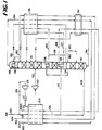
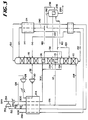
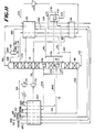
- Figures 1 through 6 and 11 illustrate the applicability of the improvement to dual reboiler/condenser process embodiments, wherein in the improvement the nitrogen vapor is removed from either the higher or lower pressure column and the pressure of the liquid oxygen is reduced prior to heat exchange.
- Figures 12 and 13 illustrate the applicability of the improvement to dual reboiler/condenser process embodiments, wherein in the improvement the nitrogen vapor is removed from the higher pressure column and the pressure of the nitrogen vapor is increased prior to heat exchange.
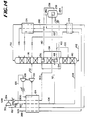
- Figure 14 illustrates the applicability of the improvement to dual reboiler/condenser embodiment, wherein in the improvement the nitrogen vapor is derived from a compressed, gaseous nitrogen product and the pressure of the liquid oxygen is increased prior to heat exchange.
- the present invention is also applicable to most multi-column, triple reboiler process cycles.
- the present invention is particularly applicable to triple reboiler processes having at least two distillation columns which are in thermal communication with each other and operating at different pressures and having a reboiler/condenser located at the bottom of the lower pressure column, wherein at least a portion of the feed air is condensed in heat exchange against boiling liquid oxygen, and another reboiler/condenser located at an intermediate location of the lower pressure column between the bottom reboiler/condenser and the third reboiler/condenser, wherein at least a portion of the nitrogen vapor from the higher pressure column is condensed in heat exchange against boiling liquid which is descending the lower pressure column.
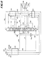
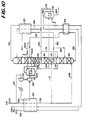
- Figures 7 through 10 illustrate triple reboiler/condenser embodiments, wherein, in the improvement, the pressure of the liquid oxygen is reduced prior to heat exchange.
- compressed, clean feed air is introduced to the process via line 100 and is split into two portions, via lines 102 and 126, respectively.
- feed air in line 102
- main heat exchanger 104 The major portion of feed air, in line 102, is cooled in main heat exchanger 104.
- This cooled air, now in line 106, is then further split into two portions, via lines 108 and 112, respectively.
- the first portion is fed via line 108 to the bottom of higher pressure column 110 for rectification.
- the second portion, in line 112, is condensed in reboiler/condenser 114 located in the bottom of lower pressure column 116.
- This condensed second portion, now in line 118 is split into two substreams via lines 120 and 122.
- the first substream, in line 120, is fed to an intermediate location of higher pressure column 110 as impure reflux.
- the second substream, in line 122, is subcooled in heat exchanger 124, reduced in pressure and fed to lower pressure column 116 at a location above the feed of the crude liquid oxygen from the bottom of higher pressure column 110 as impure reflux.
- the minor portion of the feed air, in line 126, is compressed in booster compressor 128, aftercooled, further cooled in main heat exchanger 104, work expanded in expander 130 and fed via line 132 to lower pressure column 116.
- all or part of the work produced by expander 130 can be used to drive booster compressor 128.
- the feed air fed to higher pressure column 110 is rectified into a nitrogen overhead stream, in line 134, and a crude liquid oxygen bottoms, in line 142.
- the crude liquid oxygen bottoms, in line 142 is subcooled in heat exchanger 144, reduced in pressure and fed to an intermediate location of lower pressure column 116 for distillation.
- the nitrogen overhead, in line 134 is removed from higher pressure column 110 and condensed in reboiler/condenser 136 against vaporizing liquid descending lower pressure column 116.
- Reboiler/condenser 136 is located in lower pressure column 116 at a location between reboiler/condenser 114 and the feed of crude liquid oxygen from the bottom of higher pressure column 110, line 142.
- the condensed nitrogen from reboiler/condenser 136 is split into two substreams via line 138 and 140, respectively.
- the first substream, in line 138 is fed to the top of higher pressure column 110 as reflux.
- the second portion, in line 140 is subcooled in heat exchanger 124, reduced in pressure and fed to the top of lower pressure column 116 as reflux.
- the crude liquid oxygen from the bottom of higher pressure column 110, in line 142, and the expanded second portion of feed air, in line 132, which is introduced into lower pressure column 116 is distilled into a low pressure nitrogen overhead and a liquid oxygen bottoms.
- the low pressure nitrogen overhead is removed in two portions via lines 146 and 150.
- the first portion, in line 146 is condensed against vaporizing subcooled liquid oxygen, in boiler/condenser 148 and returned to the top of lower pressure column 116 as additional reflux.
- the second portion, in line 150 is warmed to recover refrigeration in heat exchangers 124, 144 and 104 and removed as a low pressure nitrogen product via line 152.
- a portion of the liquid oxygen bottoms is vaporized in reboiler/condenser 114 thus providing boil-up for lower pressure column 116.
- Another portion is removed from lower pressure column 116 via line 160 subcooled in heat exchanger 124, reduced in pressure and fed to the sump surrounding boiler/condenser 148 wherein it is vaporized.
- the vaporized oxygen is removed via line 164, warmed in heat exchangers 124, 144 and 104 to recover refrigeration and removed as a portion of the gaseous oxygen product via line 166.
- a portion of the oxygen boil-up in lower pressure column 116 is removed via line 168, warmed in heat exchangers 144 and 104 to recover refrigeration and recovered as a second portion of the gaseous oxygen product via line 170.
- the relative quantities of the two portions of the gaseous oxygen product will depend on the operating pressure of lower pressure column 116. As the operating pressure of lower pressure column 116 is increased, the relative quantity of the second portion of the gaseous oxygen product (in
- FIG. 2 The process embodiment shown in Figure 2 is similar to the process embodiment shown in Figure 1. Throughout this disclosure, all functionally identical or equivalent equipment and streams are identified by the same number.
- the difference between Figure 1 and 2 embodiments is that, in Figure 2, the liquid oxygen bottoms portion from lower pressure column 116, in line 160, is reduced in pressure and vaporized in reboiler/condenser 236 against condensing nitrogen overhead, in line 234, from the top of higher pressure column 110.
- the condensed nitrogen, in line 238, is mixed with the condensed nitrogen, in line 140, to form low pressure reflux stream, in line 240.
- a portion of the condensed nitrogen in line 238 can be used to reflux higher pressure column 110.
- the low pressure reflux stream is subcooled in heat exchanger 124, reduced in pressure and introduced into the top of lower pressure column 116.
- a portion of the nitrogen overhead is removed via line 244, warmed to recover refrigeration and recovered via line 242, as a high pressure gaseous nitrogen product.
- the vaporized oxygen is removed via line 262, warmed in heat exchangers 144 and 104 to recover refrigeration and recovered, via line 266, as gaseous oxygen product.
- a liquid oxygen product can be removed via line 264.
- the process embodiment in Figure 3 is based on the process embodiment of Figure 2.
- the primary differences are that no high pressure nitrogen overhead is removed as product, all of the low pressure gaseous nitrogen product, in line 152, is boosted in pressure in compressor 352 and removed as a high pressure gaseous nitrogen product via line 354 and a portion of the boosted pressure nitrogen product is recycled via line 300 to the process.
- the recycle nitrogen, in line 300 is cooled in main heat exchanger 104 to a temperature near its dew point and mixed with the nitrogen overhead in line 134 to be fed to reboiler/condenser 136.
- the process embodiment shown in Figure 4 is essentially the same as process embodiment shown in Figure 3, except no liquid air reflux is provided to either higher pressure column 110 or lower pressure column 116.
- all of the cooled first portion, in line 106 is fed to reboiler/condenser 114 wherein it is partially condensed. All of this partially condensed feed air portion is then fed to the bottom of higher pressure column 110 via line 418.
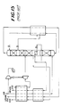
- Figure 5 depicts the process embodiment depicted in Figure 2 integrated with a gas turbine. Since the air separation process embodiment for Figure 2 has been described above, only the integration will be discussed here.
- Figure 5 represents the so-called “fully integrated” option in which all of the feed air to the air separation process is supplied by the compressor mechanically linked to the gas turbine and all of the air separation process gaseous nitrogen product is fed to the gas turbine combustor.
- "partial integration" options could be used.
- feed air is fed to the process via line 500, compressed in compressor 502 and split into air separation unit and combustion air portions, in line 504 and 510, respectively.
- the air separation unit portion is cooled in heat exchanger 506, cleaned of impurities which would freeze out at cryogenic temperatures in mole sieve unit 508 and fed to the air separation unit via line 100.
- the gaseous nitrogen product from the air separation unit, in line 152 is compressed in compressor 552, warmed in heat exchanger 506 and combined with the combustion air portion, in line 510.
- the combined combustion feed air stream, in line 512 is warmed in heat exchanger 514 and mixed with the fuel, in line 518.
- the nitrogen can be introduced at a number of alternative locations, for example, mixed directly with the fuel gas or fed directly to the combustor.
- the fuel/combustion feed air stream is combusted in combustor 520 with the combustion gas product being fed to, via line 522, and work expanded in expander 524.
- Figure 5 depicts a portion of the work produced in expander 524 as being used to compress the feed air in compressor 502. Nevertheless, all or the remaining work generated can be used for other purposes such as generating electricity.
- the expander exhaust gas, in line 526 is cooled in heat exchanger 514 and removed via line 528.
- the cooled, exhaust gas, in line 528 is then used for other purposes, such as generating steam in a combined cycle.
- both nitrogen and air (as well as fuel gas) can be loaded with water to recover low level heat before being injected into the combustor. Such cycles will not be discussed in detail here.
- Figure 6 depicts how a dual reboiler cycle shown in Figure 2 can be used for situations for which only nitrogen is the desired product or for which both nitrogen and oxygen are needed, but the oxygen product does not have to be pressurized.
- the present embodiment does not employ the use of an air compander.
- the entire feed air, in line 100 is cooled in 104.
- the cooled feed air, now in line 106 is then split into two portions as in Figure 2.
- the oxygen stream, in line 262 is warmed in heat exchanger 144 and partially in heat exchanger 104 is work expanded in expander 600.
- the resultant expanded oxygen stream, in line 665, is warmed in heat exchanger 104 to recover refrigeration and either recovered or vented, via line 666, as an ambient pressure oxygen product. Finally, a small amount of liquid nitrogen can be removed from lower pressure column 116 via line 650.
- the process embodiment in Figure 7 is a scheme with triple reboiler with both medium pressure nitrogen and air condensation.
- medium pressure it is meant that the pressure will be between the operating pressure of the high and lower pressure columns.
- the differences of this cycle from that of Figure 2 are as follow.
- This medium pressure stream, in line 732 is condensed in reboiler/condenser 740 located in lower pressure column 116 immediately below the feed position to lower pressure column 116.
- the condensed air is fed, via line 733, to lower pressure column 116 as impure reflux.
- a portion of the nitrogen gas, in line 234, is removed via line 734, warmed in heat exchanger 144, expanded to a medium pressure in expander 736 and fed via line 738 to reboiler/condenser 740.
- the expanded medium pressure nitrogen stream is condensed.
- the condensed nitrogen, in line 742, is subcooled in heat exchanger 124, reduced in pressure and fed to the top of lower pressure column 116 as additional reflux. Since extra refrigeration is produced due to nitrogen expander 736, more liquid product can be produced from this embodiment.
- the embodiment shown in Figure 8 is essentially a dual reboiler cycle and having medium pressure nitrogen condensation in the reboiler/condenser immediately below the feed position of the low pressure column only.
- This embodiment is an improvement to the process taught in US-A-4,796,431.
- the only difference between the cycle of Figure 8 and that of Figure 7 is that in the process embodiment of Figure 7 a portion of the feed air is companded (further compressed and expanded), then condensed in the same reboiler/condenser where the medium pressure nitrogen Is condensed and subsequently fed to the lower pressure column; the process embodiment of Figure 8 does not do such steps.
- the portion of nitrogen gas in line 734 after being warmed in heat exchanger 144 can be further partially warmed in heat exchanger 104 and then work expanded in expander 736.
- the embodiment shown in Figure 9 is a triple reboiler scheme with recycle nitrogen stream.
- compressed, clean feed air is cooled in main heat exchanger 104 and split into two portions, in lines 108 and 112, respectively.
- the first portion, in line 108 is fed to the bottom of higher pressure column 110 for rectification into a nitrogen overhead, in line 134, and a crude liquid oxygen bottoms, in line 142.
- the second portion, in line 112 is condensed in boiler/condenser 914 against boiling liquid oxygen, in line 160, and, via line 918, split into two portions, in lines 920 and 930, respectively.
- the first portion, in line 920 is fed as intermediate impure reflux to higher pressure column 110.
- the second portion, in line 930 is subcooled in heat exchanger 124, reduced in pressure and fed to an upper intermediate location of lower pressure column 116 as impure reflux.
- the second substream, in line 962 is companded (compressed in compressor 964, cooled in main heat exchanger 104, and work expanded in expander 966).
- the companded second nitrogen substream via line 968, is condensed in reboiler/condenser 970 located in an upper intermediate location of lower pressure column 116, subcooled, reduced in pressure and fed to the top of lower pressure column 116 as reflux.
- the process embodiment shown in Figure 10 is another triple reboiler cycle.
- the expanded air, in stream 132 is fed to and condensed in boiler/condenser 1044 against boiling crude liquid oxygen, which is a portion of the crude liquid oxygen which is removed via line 1042, reduced in pressure and fed to the sump surrounding boiler/condenser 1044.
- the condensed air, in line 1032 is reduced in pressure and fed to lower pressure column 116 with stream 122.
- the partially vaporized crude oxygen is fed, via line 1046, to the feed point of lower pressure column 116.
- the rest of the cycle is the same as that of Figure 2.
- FIG. 11 shows a dual reboiler/condenser cycle with such features. The embodiment of Figure 11 is similar to that for Figure 2; the differences are as follows.
- a gaseous oxygen product is removed via line 1168 from the bottom of higher pressure column 116 above reboiler/condenser 114, warmed in heat exchanger 104 to recover refrigeration, and recovered as a secondary gaseous oxygen product via line 1170.
- the condensed nitrogen, in line 240 is subcooled in heat exchanger 124, flashed and separated into a liquid phase and a gas phase in phase separator 1142.
- the gas phase is combined, via line 1144, with the nitrogen product, in line 150, from lower pressure column 116. At least a portion of the liquid phase, in line 1146 is fed via line 1148 to lower pressure column 116 as reflux. The remainder of the liquid phase, in line 1146, is removed as liquid nitrogen product via line 1150.
- a waste stream is removed via line 1170 from lower pressure column 116, warmed in heat exchangers 124 and 144, work expanded in expander 1172, the expanded stream, in line 1174, further warmed in heat exchangers 124, 144 and 104 to recover refrigeration and then vented via line 1176.
- the nitrogen from the top of the low pressure column or nitrogen or waste stream from the higher pressure column can be expanded in a similar manner as the waste stream from the low pressure column, no matter whether a waste stream is taken out of the low pressure column.
- a combination of two expanders can be used to eliminate the air compander.
- the pressure of the liquid oxygen removed from the lower pressure column is reduced prior to heat exchange with the nitrogen vapor.
- the pressure of the nitrogen vapor can be increased.
- Figures 12 and 13 illustrate the embodiments shown in Figures 2 and 3, respectively, except in Figures 12 and 13, the pressure of liquid oxygen stream 160 is not reduced in pressure prior to being fed to boiler/condenser 236 and the pressure of nitrogen vapor stream 234 is compressed prior to being fed to boiler/condenser 236. Compression of the nitrogen vapor can be done using cold or warm compression.
- Figure 14 illustrates an embodiment where the nitrogen vapor is derived from recycled, compressed nitrogen product.
- the embodiment of Figure 14 is similar to the embodiment of Figure 3.
- the compressed nitrogen recycle in line 302 is fed to heat exchanger 236 instead of the portion of the higher pressure nitrogen overhead in line 234.
- the pressure of the liquid oxygen boiling in boiler condenser 236 can be increased by pumping the liquid oxygen in line 160.
Landscapes
- Engineering & Computer Science (AREA)
- Physics & Mathematics (AREA)
- Mechanical Engineering (AREA)
- Thermal Sciences (AREA)
- General Engineering & Computer Science (AREA)
- Health & Medical Sciences (AREA)
- Emergency Medicine (AREA)
- Chemical & Material Sciences (AREA)
- Combustion & Propulsion (AREA)
- Separation By Low-Temperature Treatments (AREA)
Applications Claiming Priority (2)
| Application Number | Priority Date | Filing Date | Title |
|---|---|---|---|
| US07/837,786 US5257504A (en) | 1992-02-18 | 1992-02-18 | Multiple reboiler, double column, elevated pressure air separation cycles and their integration with gas turbines |
| US837786 | 1992-02-18 |
Publications (3)
| Publication Number | Publication Date |
|---|---|
| EP0556516A2 true EP0556516A2 (fr) | 1993-08-25 |
| EP0556516A3 EP0556516A3 (fr) | 1994-01-05 |
| EP0556516B1 EP0556516B1 (fr) | 1996-04-17 |
Family
ID=25275421
Family Applications (1)
| Application Number | Title | Priority Date | Filing Date |
|---|---|---|---|
| EP92311270A Revoked EP0556516B1 (fr) | 1992-02-18 | 1992-12-10 | Cycles de séparation d'air à rebouilleur, à colonne double, à pression élevée et leur intégration dans des turbines à gaz |
Country Status (9)
| Country | Link |
|---|---|
| US (1) | US5257504A (fr) |
| EP (1) | EP0556516B1 (fr) |
| JP (1) | JPH087019B2 (fr) |
| AU (1) | AU649171B2 (fr) |
| CA (1) | CA2082673C (fr) |
| DE (1) | DE69210009T2 (fr) |
| DK (1) | DK0556516T3 (fr) |
| ES (1) | ES2086088T3 (fr) |
| FI (1) | FI925125A7 (fr) |
Cited By (15)
| Publication number | Priority date | Publication date | Assignee | Title |
|---|---|---|---|---|
| FR2724011A1 (fr) * | 1994-08-29 | 1996-03-01 | Air Liquide | Procede et installation de production d'oxygene par distillation cryogenique |
| EP0824209A3 (fr) * | 1996-08-13 | 1998-09-16 | Praxair Technology, Inc. | Système de rectification cryogénique avec colonne latérale pour la fabrication d'oxygène à pureté basse et d'azote à pureté haute |
| EP0816785A3 (fr) * | 1996-06-27 | 1998-09-16 | Praxair Technology, Inc. | Système de rectification cryogénique pour la production d'oxygène à basse pureté et d'azote à haute pureté |
| EP0884543A1 (fr) * | 1997-06-13 | 1998-12-16 | L'air Liquide, Societe Anonyme Pour L'etude Et L'exploitation Des Procedes Georges Claude | Procédé et installation de séparation d'air par distillation cryogénique |
| EP0909930A1 (fr) * | 1997-10-15 | 1999-04-21 | Praxair Technology, Inc. | Système de rectification cryogénique pour la production d'oxygène basse pureté et d'oxygène haute pureté |
| EP0932000A3 (fr) * | 1998-01-22 | 1999-10-20 | Air Products And Chemicals, Inc. | Procédé pour la production d'oxygène |
| EP0932002A3 (fr) * | 1998-01-22 | 1999-10-20 | Air Products And Chemicals, Inc. | Procédé à détendeur unique et à compresseur froid pour la production d'oxygène |
| EP0931999A3 (fr) * | 1998-01-22 | 1999-10-20 | Air Products And Chemicals, Inc. | Procédé à détendeur multiple pour la production d'oxygène |
| EP0932001A3 (fr) * | 1998-01-22 | 1999-10-20 | Air Products And Chemicals, Inc. | Procédé de séparation d'air en utilisant des détendeurs chauds et froids |
| EP1063485A1 (fr) * | 1999-06-22 | 2000-12-27 | L'air Liquide Société Anonyme pour l'étude et l'exploitation des procédés Georges Claude | Appareil et procédé de séparation d'air par distillation cryogénique |
| EP0633438B2 (fr) † | 1993-07-05 | 2002-04-17 | The BOC Group plc | Séparation de l'air |
| FR2874249A1 (fr) * | 2004-08-10 | 2006-02-17 | Air Liquide | Procede et installation de separation d'air par distillation cryogenique |
| FR2930327A1 (fr) * | 2008-04-22 | 2009-10-23 | Air Liquide | Procede et appareil de separation d'air par distillation cryogenique |
| WO2009136077A3 (fr) * | 2008-04-22 | 2010-01-07 | L'air Liquide Societe Anonyme Pour L'etude Et L'exploitation Des Procedes Georges Claude | Procede et appareil de separation d'air par distillation cryogenique |
| EP2482265A3 (fr) * | 2011-01-31 | 2014-04-09 | Sony Computer Entertainment Inc. | Contrôleur à distance et procédé de contrôle de l'émission de lumière d'une unité électroluminescente correspondante |
Families Citing this family (23)
| Publication number | Priority date | Publication date | Assignee | Title |
|---|---|---|---|---|
| US5315833A (en) * | 1991-10-15 | 1994-05-31 | Liquid Air Engineering Corporation | Process for the mixed production of high and low purity oxygen |
| GB9213776D0 (en) * | 1992-06-29 | 1992-08-12 | Boc Group Plc | Air separation |
| US5341646A (en) * | 1993-07-15 | 1994-08-30 | Air Products And Chemicals, Inc. | Triple column distillation system for oxygen and pressurized nitrogen production |
| GB9500120D0 (en) * | 1995-01-05 | 1995-03-01 | Boc Group Plc | Air separation |
| US5678426A (en) * | 1995-01-20 | 1997-10-21 | Air Products And Chemicals, Inc. | Separation of fluid mixtures in multiple distillation columns |
| US5692395A (en) * | 1995-01-20 | 1997-12-02 | Agrawal; Rakesh | Separation of fluid mixtures in multiple distillation columns |
| US5513497A (en) * | 1995-01-20 | 1996-05-07 | Air Products And Chemicals, Inc. | Separation of fluid mixtures in multiple distillation columns |
| US5501078A (en) * | 1995-04-24 | 1996-03-26 | Praxair Technology, Inc. | System and method for operating an integrated gas turbine and cryogenic air separation plant under turndown conditions |
| US5678425A (en) * | 1996-06-07 | 1997-10-21 | Air Products And Chemicals, Inc. | Method and apparatus for producing liquid products from air in various proportions |
| US5761927A (en) * | 1997-04-29 | 1998-06-09 | Air Products And Chemicals, Inc. | Process to produce nitrogen using a double column and three reboiler/condensers |
| US6116027A (en) * | 1998-09-29 | 2000-09-12 | Air Products And Chemicals, Inc. | Supplemental air supply for an air separation system |
| US6116052A (en) * | 1999-04-09 | 2000-09-12 | Air Liquide Process And Construction | Cryogenic air separation process and installation |
| US6347534B1 (en) | 1999-05-25 | 2002-02-19 | Air Liquide Process And Construction | Cryogenic distillation system for air separation |
| US6196024B1 (en) | 1999-05-25 | 2001-03-06 | L'air Liquide, Societe Anonyme Pour L'etude Et L'exploitation Des Procedes Georges Claude | Cryogenic distillation system for air separation |
| US6202441B1 (en) | 1999-05-25 | 2001-03-20 | Air Liquide Process And Construction, Inc. | Cryogenic distillation system for air separation |
| US6276170B1 (en) | 1999-05-25 | 2001-08-21 | Air Liquide Process And Construction | Cryogenic distillation system for air separation |
| US6263659B1 (en) | 1999-06-04 | 2001-07-24 | Air Products And Chemicals, Inc. | Air separation process integrated with gas turbine combustion engine driver |
| US6256994B1 (en) | 1999-06-04 | 2001-07-10 | Air Products And Chemicals, Inc. | Operation of an air separation process with a combustion engine for the production of atmospheric gas products and electric power |
| US6345493B1 (en) | 1999-06-04 | 2002-02-12 | Air Products And Chemicals, Inc. | Air separation process and system with gas turbine drivers |
| US11118834B2 (en) * | 2013-03-19 | 2021-09-14 | Linde Aktiengesellschaft | Method and device for generating gaseous compressed nitrogen |
| CN104251599A (zh) * | 2014-07-12 | 2014-12-31 | 孙竟成 | 超低压空分设备工艺流程 |
| CN111527361B (zh) * | 2017-12-29 | 2022-03-04 | 乔治洛德方法研究和开发液化空气有限公司 | 一种基于深冷精馏生产空气产品的方法及设备 |
| US12510294B2 (en) * | 2020-04-09 | 2025-12-30 | Linde Gmbh | Process for cryogenic fractionation of air, air fractionation plant and integrated system composed of at least two air fractionation plants |
Family Cites Families (18)
| Publication number | Priority date | Publication date | Assignee | Title |
|---|---|---|---|---|
| US3210951A (en) * | 1960-08-25 | 1965-10-12 | Air Prod & Chem | Method for low temperature separation of gaseous mixtures |
| US4224045A (en) * | 1978-08-23 | 1980-09-23 | Union Carbide Corporation | Cryogenic system for producing low-purity oxygen |
| US4448595A (en) * | 1982-12-02 | 1984-05-15 | Union Carbide Corporation | Split column multiple condenser-reboiler air separation process |
| US4557735A (en) * | 1984-02-21 | 1985-12-10 | Union Carbide Corporation | Method for preparing air for separation by rectification |
| US4732595A (en) * | 1985-08-23 | 1988-03-22 | Daidousanso Co., Ltd. | Oxygen gas production apparatus |
| US4796431A (en) * | 1986-07-15 | 1989-01-10 | Erickson Donald C | Nitrogen partial expansion refrigeration for cryogenic air separation |
| US4702757A (en) * | 1986-08-20 | 1987-10-27 | Air Products And Chemicals, Inc. | Dual air pressure cycle to produce low purity oxygen |
| US4784677A (en) * | 1987-07-16 | 1988-11-15 | The Boc Group, Inc. | Process and apparatus for controlling argon column feedstreams |
| US4775399A (en) * | 1987-11-17 | 1988-10-04 | Erickson Donald C | Air fractionation improvements for nitrogen production |
| DE3913880A1 (de) * | 1989-04-27 | 1990-10-31 | Linde Ag | Verfahren und vorrichtung zur tieftemperaturzerlegung von luft |
| US4936099A (en) * | 1989-05-19 | 1990-06-26 | Air Products And Chemicals, Inc. | Air separation process for the production of oxygen-rich and nitrogen-rich products |
| WO1993013373A1 (fr) * | 1989-09-12 | 1993-07-08 | Ha Bao V | Appareil et procede cryogeniques de separation d'air |
| GB8921428D0 (en) * | 1989-09-22 | 1989-11-08 | Boc Group Plc | Separation of air |
| US5006139A (en) * | 1990-03-09 | 1991-04-09 | Air Products And Chemicals, Inc. | Cryogenic air separation process for the production of nitrogen |
| US5006137A (en) * | 1990-03-09 | 1991-04-09 | Air Products And Chemicals, Inc. | Nitrogen generator with dual reboiler/condensers in the low pressure distillation column |
| US5098456A (en) * | 1990-06-27 | 1992-03-24 | Union Carbide Industrial Gases Technology Corporation | Cryogenic air separation system with dual feed air side condensers |
| KR101846767B1 (ko) | 2014-04-02 | 2018-04-06 | 도요타지도샤가부시키가이샤 | 비수 전해질 2차 전지 |
| JP6354992B2 (ja) | 2015-04-02 | 2018-07-11 | 住友電装株式会社 | コネクタ |
-
1992
- 1992-02-18 US US07/837,786 patent/US5257504A/en not_active Expired - Fee Related
- 1992-11-11 FI FI925125A patent/FI925125A7/fi unknown
- 1992-11-12 CA CA002082673A patent/CA2082673C/fr not_active Expired - Fee Related
- 1992-11-16 AU AU28421/92A patent/AU649171B2/en not_active Ceased
- 1992-12-10 DK DK92311270.0T patent/DK0556516T3/da active
- 1992-12-10 ES ES92311270T patent/ES2086088T3/es not_active Expired - Lifetime
- 1992-12-10 DE DE69210009T patent/DE69210009T2/de not_active Revoked
- 1992-12-10 EP EP92311270A patent/EP0556516B1/fr not_active Revoked
-
1993
- 1993-02-15 JP JP5025349A patent/JPH087019B2/ja not_active Expired - Lifetime
Cited By (23)
| Publication number | Priority date | Publication date | Assignee | Title |
|---|---|---|---|---|
| EP0633438B2 (fr) † | 1993-07-05 | 2002-04-17 | The BOC Group plc | Séparation de l'air |
| EP0699884A1 (fr) * | 1994-08-29 | 1996-03-06 | L'air Liquide, Societe Anonyme Pour L'etude Et L'exploitation Des Procedes Georges Claude | Procédé et installation de production d'oxygène par distillation cryogénique |
| US5626036A (en) * | 1994-08-29 | 1997-05-06 | L'air Liquide Societe Anonyme Pour L'etude Et L'exploitation Des Procedes Georges Claude | Process for the production of oxygen by cryogenic distillation |
| AU705278B2 (en) * | 1994-08-29 | 1999-05-20 | L'air Liquide, Societe Anonyme Pour L'etude Et L'exploitation Des Procedes Georges Claude | Process and installation for the production of oxygen by cryogenic distillation |
| FR2724011A1 (fr) * | 1994-08-29 | 1996-03-01 | Air Liquide | Procede et installation de production d'oxygene par distillation cryogenique |
| EP0816785A3 (fr) * | 1996-06-27 | 1998-09-16 | Praxair Technology, Inc. | Système de rectification cryogénique pour la production d'oxygène à basse pureté et d'azote à haute pureté |
| EP0824209A3 (fr) * | 1996-08-13 | 1998-09-16 | Praxair Technology, Inc. | Système de rectification cryogénique avec colonne latérale pour la fabrication d'oxygène à pureté basse et d'azote à pureté haute |
| US6047562A (en) * | 1997-06-13 | 2000-04-11 | L'air Liquide, Societe Anonyme Pour L'etude Et L'exploitation Des Procedes Georges Claude | Process and plant for separating air by cryogenic distillation |
| EP0884543A1 (fr) * | 1997-06-13 | 1998-12-16 | L'air Liquide, Societe Anonyme Pour L'etude Et L'exploitation Des Procedes Georges Claude | Procédé et installation de séparation d'air par distillation cryogénique |
| FR2764681A1 (fr) * | 1997-06-13 | 1998-12-18 | Air Liquide | Procede et installation de separation d'air par distillation cryogenique |
| EP0909930A1 (fr) * | 1997-10-15 | 1999-04-21 | Praxair Technology, Inc. | Système de rectification cryogénique pour la production d'oxygène basse pureté et d'oxygène haute pureté |
| EP0932002A3 (fr) * | 1998-01-22 | 1999-10-20 | Air Products And Chemicals, Inc. | Procédé à détendeur unique et à compresseur froid pour la production d'oxygène |
| EP0932001A3 (fr) * | 1998-01-22 | 1999-10-20 | Air Products And Chemicals, Inc. | Procédé de séparation d'air en utilisant des détendeurs chauds et froids |
| EP0931999A3 (fr) * | 1998-01-22 | 1999-10-20 | Air Products And Chemicals, Inc. | Procédé à détendeur multiple pour la production d'oxygène |
| EP0932000A3 (fr) * | 1998-01-22 | 1999-10-20 | Air Products And Chemicals, Inc. | Procédé pour la production d'oxygène |
| EP1063485A1 (fr) * | 1999-06-22 | 2000-12-27 | L'air Liquide Société Anonyme pour l'étude et l'exploitation des procédés Georges Claude | Appareil et procédé de séparation d'air par distillation cryogénique |
| FR2795496A1 (fr) * | 1999-06-22 | 2000-12-29 | Air Liquide | Appareil et procede de separation d'air par distillation cryogenique |
| US6339938B1 (en) | 1999-06-22 | 2002-01-22 | L'air Liquide, Societe Anonyme Pour L'etude Et L'exploitation Des Procedes Georges Claude | Apparatus and process for separating air by cryogenic distillation |
| FR2874249A1 (fr) * | 2004-08-10 | 2006-02-17 | Air Liquide | Procede et installation de separation d'air par distillation cryogenique |
| FR2930327A1 (fr) * | 2008-04-22 | 2009-10-23 | Air Liquide | Procede et appareil de separation d'air par distillation cryogenique |
| WO2009136077A3 (fr) * | 2008-04-22 | 2010-01-07 | L'air Liquide Societe Anonyme Pour L'etude Et L'exploitation Des Procedes Georges Claude | Procede et appareil de separation d'air par distillation cryogenique |
| EP2482265A3 (fr) * | 2011-01-31 | 2014-04-09 | Sony Computer Entertainment Inc. | Contrôleur à distance et procédé de contrôle de l'émission de lumière d'une unité électroluminescente correspondante |
| US9189956B2 (en) | 2011-01-31 | 2015-11-17 | Sony Corporation | Remote controller and method of controlling light emission from light-emitting unit thereof |
Also Published As
| Publication number | Publication date |
|---|---|
| AU649171B2 (en) | 1994-05-12 |
| US5257504A (en) | 1993-11-02 |
| ES2086088T3 (es) | 1996-06-16 |
| CA2082673A1 (fr) | 1993-08-19 |
| DE69210009D1 (de) | 1996-05-23 |
| EP0556516A3 (fr) | 1994-01-05 |
| EP0556516B1 (fr) | 1996-04-17 |
| FI925125A0 (fi) | 1992-11-11 |
| JPH087019B2 (ja) | 1996-01-29 |
| DK0556516T3 (da) | 1996-05-13 |
| JPH06117753A (ja) | 1994-04-28 |
| FI925125A7 (fi) | 1993-08-19 |
| AU2842192A (en) | 1993-08-19 |
| DE69210009T2 (de) | 1996-11-14 |
| CA2082673C (fr) | 1995-09-19 |
Similar Documents
| Publication | Publication Date | Title |
|---|---|---|
| EP0556516B1 (fr) | Cycles de séparation d'air à rebouilleur, à colonne double, à pression élevée et leur intégration dans des turbines à gaz | |
| EP0584419B1 (fr) | Procédé et installation de distillation d'air | |
| EP0645595B1 (fr) | Schémas de séparation d'air pour la coproduction d'oxygène et d'azote comme produit gazeux et/ou liquide | |
| JP2758355B2 (ja) | 酸素と加圧窒素を製造するための低温空気分離方法 | |
| EP0644388B1 (fr) | Séparation cryogénique d'air | |
| US5251449A (en) | Process and apparatus for air fractionation by rectification | |
| EP0795728A2 (fr) | Turbine à combustion et système de séparation d'air sous pression élevée avec récupération d'argon | |
| US5392609A (en) | Process and apparatus for the production of impure oxygen | |
| EP0584420B1 (fr) | Cycle de séparation d'air à colonne unique et son intégration dans des turbines à gaz | |
| US4783210A (en) | Air separation process with modified single distillation column nitrogen generator | |
| US5255522A (en) | Vaporization of liquid oxygen for increased argon recovery | |
| EP0635690A1 (fr) | Système de rectification cryogénique pour la fabrication de l'oxygène à pureté basse | |
| EP0646755A1 (fr) | Procédé de séparation cryogénique d'air pour la production d'azote sous pression élevé à partir d'azote liquide pompée | |
| EP0932003A2 (fr) | Procédé de séparation d'air sous pression élevée en utilisant la détente d'un gaz perdu pour la compression d'un courant d'alimentation | |
| EP0902245A1 (fr) | Procédé cryogénique de séparation des gaz de l'air | |
| US5255524A (en) | Dual heat pump cycles for increased argon recovery | |
| US5245831A (en) | Single heat pump cycle for increased argon recovery | |
| EP0931999B1 (fr) | Procédé à détendeur multiple pour la production d'oxygène |
Legal Events
| Date | Code | Title | Description |
|---|---|---|---|
| PUAI | Public reference made under article 153(3) epc to a published international application that has entered the european phase |
Free format text: ORIGINAL CODE: 0009012 |
|
| AK | Designated contracting states |
Kind code of ref document: A2 Designated state(s): BE DE DK ES FR GB IT NL SE |
|
| PUAL | Search report despatched |
Free format text: ORIGINAL CODE: 0009013 |
|
| AK | Designated contracting states |
Kind code of ref document: A3 Designated state(s): BE DE DK ES FR GB IT NL SE |
|
| 17P | Request for examination filed |
Effective date: 19940323 |
|
| 17Q | First examination report despatched |
Effective date: 19940728 |
|
| GRAA | (expected) grant |
Free format text: ORIGINAL CODE: 0009210 |
|
| AK | Designated contracting states |
Kind code of ref document: B1 Designated state(s): BE DE DK ES FR GB IT NL SE |
|
| ITF | It: translation for a ep patent filed | ||
| REG | Reference to a national code |
Ref country code: DK Ref legal event code: T3 |
|
| REF | Corresponds to: |
Ref document number: 69210009 Country of ref document: DE Date of ref document: 19960523 |
|
| REG | Reference to a national code |
Ref country code: ES Ref legal event code: FG2A Ref document number: 2086088 Country of ref document: ES Kind code of ref document: T3 |
|
| ET | Fr: translation filed | ||
| GRAH | Despatch of communication of intention to grant a patent |
Free format text: ORIGINAL CODE: EPIDOS IGRA |
|
| PGFP | Annual fee paid to national office [announced via postgrant information from national office to epo] |
Ref country code: DK Payment date: 19960917 Year of fee payment: 5 |
|
| PGFP | Annual fee paid to national office [announced via postgrant information from national office to epo] |
Ref country code: NL Payment date: 19960924 Year of fee payment: 5 |
|
| PGFP | Annual fee paid to national office [announced via postgrant information from national office to epo] |
Ref country code: GB Payment date: 19961108 Year of fee payment: 5 |
|
| PGFP | Annual fee paid to national office [announced via postgrant information from national office to epo] |
Ref country code: SE Payment date: 19961119 Year of fee payment: 5 |
|
| PGFP | Annual fee paid to national office [announced via postgrant information from national office to epo] |
Ref country code: FR Payment date: 19961211 Year of fee payment: 5 |
|
| PGFP | Annual fee paid to national office [announced via postgrant information from national office to epo] |
Ref country code: ES Payment date: 19961219 Year of fee payment: 5 |
|
| PGFP | Annual fee paid to national office [announced via postgrant information from national office to epo] |
Ref country code: DE Payment date: 19961227 Year of fee payment: 5 |
|
| PGFP | Annual fee paid to national office [announced via postgrant information from national office to epo] |
Ref country code: BE Payment date: 19970108 Year of fee payment: 5 |
|
| PLBQ | Unpublished change to opponent data |
Free format text: ORIGINAL CODE: EPIDOS OPPO |
|
| PLBI | Opposition filed |
Free format text: ORIGINAL CODE: 0009260 |
|
| PLBF | Reply of patent proprietor to notice(s) of opposition |
Free format text: ORIGINAL CODE: EPIDOS OBSO |
|
| 26 | Opposition filed |
Opponent name: L'AIR LIQUIDE, S.A. POUR L'ETUDE ET L'EXPLOITATION Effective date: 19970117 |
|
| NLR1 | Nl: opposition has been filed with the epo |
Opponent name: L'AIR LIQUIDE, S.A. POUR L'ETUDE ET L'EXPLOITATION |
|
| PLBF | Reply of patent proprietor to notice(s) of opposition |
Free format text: ORIGINAL CODE: EPIDOS OBSO |
|
| RDAH | Patent revoked |
Free format text: ORIGINAL CODE: EPIDOS REVO |
|
| REG | Reference to a national code |
Ref country code: DK Ref legal event code: EBP |
|
| RDAG | Patent revoked |
Free format text: ORIGINAL CODE: 0009271 |
|
| 27W | Patent revoked |
Effective date: 19970711 |
|
| GBPR | Gb: patent revoked under art. 102 of the ep convention designating the uk as contracting state |
Free format text: 970711 |
|
| NLR2 | Nl: decision of opposition |