EP0556635A2 - Ultraschallwanddickenmessvorrichtung, insbesondere für extrudierte Rohre - Google Patents
Ultraschallwanddickenmessvorrichtung, insbesondere für extrudierte Rohre Download PDFInfo
- Publication number
- EP0556635A2 EP0556635A2 EP93101622A EP93101622A EP0556635A2 EP 0556635 A2 EP0556635 A2 EP 0556635A2 EP 93101622 A EP93101622 A EP 93101622A EP 93101622 A EP93101622 A EP 93101622A EP 0556635 A2 EP0556635 A2 EP 0556635A2
- Authority
- EP
- European Patent Office
- Prior art keywords
- wall thickness
- measuring device
- passage opening
- long product
- thickness measuring
- Prior art date
- Legal status (The legal status is an assumption and is not a legal conclusion. Google has not performed a legal analysis and makes no representation as to the accuracy of the status listed.)
- Granted
Links
Images
Classifications
-
- G—PHYSICS
- G01—MEASURING; TESTING
- G01B—MEASURING LENGTH, THICKNESS OR SIMILAR LINEAR DIMENSIONS; MEASURING ANGLES; MEASURING AREAS; MEASURING IRREGULARITIES OF SURFACES OR CONTOURS
- G01B17/00—Measuring arrangements characterised by the use of infrasonic, sonic or ultrasonic vibrations
- G01B17/02—Measuring arrangements characterised by the use of infrasonic, sonic or ultrasonic vibrations for measuring thickness
-
- B—PERFORMING OPERATIONS; TRANSPORTING
- B21—MECHANICAL METAL-WORKING WITHOUT ESSENTIALLY REMOVING MATERIAL; PUNCHING METAL
- B21C—MANUFACTURE OF METAL SHEETS, WIRE, RODS, TUBES, PROFILES OR LIKE SEMI-MANUFACTURED PRODUCTS OTHERWISE THAN BY ROLLING; AUXILIARY OPERATIONS USED IN CONNECTION WITH METAL-WORKING WITHOUT ESSENTIALLY REMOVING MATERIAL
- B21C51/00—Measuring, gauging, indicating, counting, or marking devices specially adapted for use in the production or manipulation of material in accordance with subclasses B21B - B21F
-
- B—PERFORMING OPERATIONS; TRANSPORTING
- B29—WORKING OF PLASTICS; WORKING OF SUBSTANCES IN A PLASTIC STATE IN GENERAL
- B29C—SHAPING OR JOINING OF PLASTICS; SHAPING OF MATERIAL IN A PLASTIC STATE, NOT OTHERWISE PROVIDED FOR; AFTER-TREATMENT OF THE SHAPED PRODUCTS, e.g. REPAIRING
- B29C48/00—Extrusion moulding, i.e. expressing the moulding material through a die or nozzle which imparts the desired form; Apparatus therefor
- B29C48/25—Component parts, details or accessories; Auxiliary operations
- B29C48/92—Measuring, controlling or regulating
-
- G—PHYSICS
- G01—MEASURING; TESTING
- G01N—INVESTIGATING OR ANALYSING MATERIALS BY DETERMINING THEIR CHEMICAL OR PHYSICAL PROPERTIES
- G01N29/00—Investigating or analysing materials by the use of ultrasonic, sonic or infrasonic waves; Visualisation of the interior of objects by transmitting ultrasonic or sonic waves through the object
- G01N29/22—Details, e.g. general constructional or apparatus details
- G01N29/28—Details, e.g. general constructional or apparatus details providing acoustic coupling, e.g. water
-
- G—PHYSICS
- G01—MEASURING; TESTING
- G01S—RADIO DIRECTION-FINDING; RADIO NAVIGATION; DETERMINING DISTANCE OR VELOCITY BY USE OF RADIO WAVES; LOCATING OR PRESENCE-DETECTING BY USE OF THE REFLECTION OR RERADIATION OF RADIO WAVES; ANALOGOUS ARRANGEMENTS USING OTHER WAVES
- G01S7/00—Details of systems according to groups G01S13/00, G01S15/00, G01S17/00
- G01S7/52—Details of systems according to groups G01S13/00, G01S15/00, G01S17/00 of systems according to group G01S15/00
- G01S7/52004—Means for monitoring or calibrating
-
- B—PERFORMING OPERATIONS; TRANSPORTING
- B21—MECHANICAL METAL-WORKING WITHOUT ESSENTIALLY REMOVING MATERIAL; PUNCHING METAL
- B21B—ROLLING OF METAL
- B21B23/00—Tube-rolling not restricted to methods provided for in only one of groups B21B17/00, B21B19/00, B21B21/00, e.g. combined processes planetary tube rolling, auxiliary arrangements, e.g. lubricating, special tube blanks, continuous casting combined with tube rolling
-
- B—PERFORMING OPERATIONS; TRANSPORTING
- B29—WORKING OF PLASTICS; WORKING OF SUBSTANCES IN A PLASTIC STATE IN GENERAL
- B29C—SHAPING OR JOINING OF PLASTICS; SHAPING OF MATERIAL IN A PLASTIC STATE, NOT OTHERWISE PROVIDED FOR; AFTER-TREATMENT OF THE SHAPED PRODUCTS, e.g. REPAIRING
- B29C2948/00—Indexing scheme relating to extrusion moulding
- B29C2948/92—Measuring, controlling or regulating
- B29C2948/92009—Measured parameter
- B29C2948/92114—Dimensions
- B29C2948/92152—Thickness
-
- B—PERFORMING OPERATIONS; TRANSPORTING
- B29—WORKING OF PLASTICS; WORKING OF SUBSTANCES IN A PLASTIC STATE IN GENERAL
- B29C—SHAPING OR JOINING OF PLASTICS; SHAPING OF MATERIAL IN A PLASTIC STATE, NOT OTHERWISE PROVIDED FOR; AFTER-TREATMENT OF THE SHAPED PRODUCTS, e.g. REPAIRING
- B29C2948/00—Indexing scheme relating to extrusion moulding
- B29C2948/92—Measuring, controlling or regulating
- B29C2948/92323—Location or phase of measurement
- B29C2948/92361—Extrusion unit
- B29C2948/92409—Die; Nozzle zone
-
- B—PERFORMING OPERATIONS; TRANSPORTING
- B29—WORKING OF PLASTICS; WORKING OF SUBSTANCES IN A PLASTIC STATE IN GENERAL
- B29C—SHAPING OR JOINING OF PLASTICS; SHAPING OF MATERIAL IN A PLASTIC STATE, NOT OTHERWISE PROVIDED FOR; AFTER-TREATMENT OF THE SHAPED PRODUCTS, e.g. REPAIRING
- B29C2948/00—Indexing scheme relating to extrusion moulding
- B29C2948/92—Measuring, controlling or regulating
- B29C2948/92323—Location or phase of measurement
- B29C2948/92428—Calibration, after-treatment, or cooling zone
-
- B—PERFORMING OPERATIONS; TRANSPORTING
- B29—WORKING OF PLASTICS; WORKING OF SUBSTANCES IN A PLASTIC STATE IN GENERAL
- B29C—SHAPING OR JOINING OF PLASTICS; SHAPING OF MATERIAL IN A PLASTIC STATE, NOT OTHERWISE PROVIDED FOR; AFTER-TREATMENT OF THE SHAPED PRODUCTS, e.g. REPAIRING
- B29C2948/00—Indexing scheme relating to extrusion moulding
- B29C2948/92—Measuring, controlling or regulating
- B29C2948/92323—Location or phase of measurement
- B29C2948/92438—Conveying, transporting or storage of articles
-
- B—PERFORMING OPERATIONS; TRANSPORTING
- B29—WORKING OF PLASTICS; WORKING OF SUBSTANCES IN A PLASTIC STATE IN GENERAL
- B29C—SHAPING OR JOINING OF PLASTICS; SHAPING OF MATERIAL IN A PLASTIC STATE, NOT OTHERWISE PROVIDED FOR; AFTER-TREATMENT OF THE SHAPED PRODUCTS, e.g. REPAIRING
- B29C2948/00—Indexing scheme relating to extrusion moulding
- B29C2948/92—Measuring, controlling or regulating
- B29C2948/92504—Controlled parameter
- B29C2948/92609—Dimensions
- B29C2948/92647—Thickness
-
- B—PERFORMING OPERATIONS; TRANSPORTING
- B29—WORKING OF PLASTICS; WORKING OF SUBSTANCES IN A PLASTIC STATE IN GENERAL
- B29C—SHAPING OR JOINING OF PLASTICS; SHAPING OF MATERIAL IN A PLASTIC STATE, NOT OTHERWISE PROVIDED FOR; AFTER-TREATMENT OF THE SHAPED PRODUCTS, e.g. REPAIRING
- B29C2948/00—Indexing scheme relating to extrusion moulding
- B29C2948/92—Measuring, controlling or regulating
- B29C2948/92819—Location or phase of control
- B29C2948/92933—Conveying, transporting or storage of articles
-
- G—PHYSICS
- G01—MEASURING; TESTING
- G01N—INVESTIGATING OR ANALYSING MATERIALS BY DETERMINING THEIR CHEMICAL OR PHYSICAL PROPERTIES
- G01N2291/00—Indexing codes associated with group G01N29/00
- G01N2291/02—Indexing codes associated with the analysed material
- G01N2291/028—Material parameters
- G01N2291/02854—Length, thickness
Definitions
- the invention relates to an ultrasonic wall thickness measuring device for in particular extruded long products, such as pipes, with at least one sensor arranged in a passage opening for the long product, on the transmitter and receiver side of which a chamber which can be filled with a coupling liquid and is open to the passage opening is provided, whereby in the direction of flow in front of each sensor and axially aligned with it, at least one outlet for the coupling liquid is provided which is open towards the passage opening.
- a prerequisite for an error-free measurement by means of the sensors is that the coupling liquid This requirement cannot be met easily on the surface of the tube, in particular if the material of the long product has a high surface tension, as is the case with polyolefin-based materials Measuring device at the entrance to the D Through passage opening an annular outlet for coupling liquid is provided. A first wetting of the surface of the long product already takes place through this coupling liquid. In practice, however, it has been shown that even this additional measure does not yet lead to satisfactory results.
- the invention has for its object to provide an ultrasonic wall thickness measuring device in which the measurement errors caused by bubbles on the surface of the long product to be measured in the wall thickness are largely eliminated.
- each outlet upstream of the chamber for the coupling liquid is designed as a spray nozzle on the inlet side of the passage opening and is directed against the surface of the long product.
- the ultrasonic wall thickness measuring device With the ultrasonic wall thickness measuring device according to the invention, the surface of the long product is effectively wetted due to the kinetic energy of the sprayed-on coupling liquid, so that the long product is free of bubbles in the area of the ultrasonic measuring position.
- the ultrasonic wall thickness measuring device therefore works with a higher operational reliability than the known measuring devices, i.e. no incorrect measurements.
- the surface wetting by the coupling liquid emerging from each spray nozzle is particularly effective when the spray direction of each spray nozzle is inclined to the surface of the long product and has a component directed against the direction of rotation. In this spraying direction, bubbles are driven away from the surface of the long product in front of the flow opening.
- the inlet side of the passage opening, in which each spray nozzle is arranged should be conical or funnel-shaped.
- the individual spray nozzles can also be replaced by a spray ring.
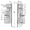
- the drawing shows an ultrasonic wall thickness measuring device in axial section.
- a through opening 2 for a long product, here an extruded tube 3, is formed in a carrier 1.
- a plurality of ultrasonic sensors 4, 5 are used in the carrier 1 distributed over the circumference.
- the end-side transmitter and receiver sides 4a, 5a of the sensors 4, 5 face an annular chamber 6 formed in the carrier 1 and which is open to the passage opening 2.
- Radial connecting bores 4b, 5b are formed in the carrier 1 between this chamber 6 and the transmitter and receiver sides 4a, 5a.
- a coupling medium e.g. Water
- the coupling medium fills the entire radial space between the surface of the tube 3 and the transmitter and receiver sides 4a, 5a of the sensors 4, 5.
- the axial channels 8, 9 also open into an annular space 10, which is arranged upstream in the direction of flow R of the tube 3 of the chamber 6 and via which coupling liquid is brought onto the surface of the tube 3.
- the ultrasonic wall thickness measuring device described so far is state of the art.
- the carrier 1 on the input side carries a ring 11 with a funnel-shaped input side 11a.
- An annular space 12 is formed in the ring 11, to which coupling liquid is supplied under pressure via a feed line 13.
- a large number of spray nozzles 14, 15 are arranged, which are fed from the annular space 12.
- the spray direction of these spray nozzles 14, 15 is to the surface of the raw res 3 inclined and has a flow component pointing against the flow direction R. As a result, air bubbles forming on the surface of the pipe 3 are driven away from the pipe surface.
Landscapes
- Engineering & Computer Science (AREA)
- General Physics & Mathematics (AREA)
- Physics & Mathematics (AREA)
- Mechanical Engineering (AREA)
- Life Sciences & Earth Sciences (AREA)
- Radar, Positioning & Navigation (AREA)
- Remote Sensing (AREA)
- Health & Medical Sciences (AREA)
- Computer Networks & Wireless Communication (AREA)
- Chemical & Material Sciences (AREA)
- Analytical Chemistry (AREA)
- Biochemistry (AREA)
- General Health & Medical Sciences (AREA)
- Immunology (AREA)
- Pathology (AREA)
- Length Measuring Devices Characterised By Use Of Acoustic Means (AREA)
Abstract
Description
- Die Erfindung bezieht sich auf eine Ultraschallwanddickenmeßvorrichtung für insbesondere extrudierte Langprodukte, wie Rohre, mit mindestens einem in eine Durchlauföffnung für das Langprodukt aufweisenden Träger angeordneten Sensor, an dessen Sender- und Empfängerseite eine mit einer Kopplungsflüssigkeit füllbare, zur Durchlauföffnung hin offene Kammer vorgesehen ist, wobei in Durchlaufrichtung vor jedem Sensor und axial mit ihm in einer Flucht mindestens ein zur Durchlauföffnung hin offener Auslaß für die Kopplungsflüssigkeit vorgesehen ist.
- Bei einer solchen auf dem Markt befindlichen Ultraschallwanddickenmeßvorrichtung (Prospekt der Firma INOEX GmbH, Borweg 27, D-4970 Bad Oeynhausen 1, "AUREX/USS-GEO" sind in dem Träger über dessen Umfang verteilt mehrere Sensoren angeordnet, denen eine gemeinsame Ringkammer zugeordnet ist. Bei in der Durchlauföffnung befindlichem Rohr schließt die Oberfläche des Rohres diese Ringkammer ab. Eine solche Ultraschallwanddickenmeßvorrichtung ist nicht nur zur Messung der Wanddicke, sondern auch zur Messung des Durchmessers des Rohres geeignet. Voraussetzung für eine fehlerfreie Messung mittels der Sensoren ist, daß die Kopplungsflüssigkeit blasenfrei ist. Diese Forderung ist an der Oberfläche des Rohres insbesondere dann nicht ohne weiteres zu erfüllen, wenn das Material des Langproduktes eine hohe Oberflächenspannung aufweist, wie es bei Materialien auf Polyolefinbasis der Fall ist. Um solche Meßfehler zu vermindern, ist schon bei der bekannten Meßvorrichtung am Eingang der Durchlauföffnung ein ringförmiger Auslaß für Kopplungsflüssigkeit vorgesehen. Durch diese Kopplungsflüssigkeit findet also schon eine erste Benetzung der Oberfläche des Langproduktes statt. In der Praxis hat sich aber gezeigt, daß selbst diese zusätzliche Maßnahme noch nicht zu zufriedenstellenden Ergebnissen führt.
- Der Erfindung liegt die Aufgabe zugrunde, eine Ultraschallwanddickenmeßvorrichtung zu schaffen, bei der die durch Bläschenbildung an der Oberfläche des in der Wanddicke zu messenden Langproduktes bedingten Meßfehler weitgehendst eliminiert sind.
- Diese Aufgabe wird bei einer Ultraschallwanddickenmeßvorrichtung der eingangs genannten Art dadurch gelöst, daß jeder der Kammer vorgeordnete Auslaß für die Kopplungsflüssigkeit als Spritzdüse an der Eingangsseite der Durchlauföffnung ausgebildet ist und gegen die Oberfläche des Langproduktes gerichtet ist.
- Mit der erfindungsgemäßen Ultraschallwanddikkenmeßvorrichtung wird aufgrund der kinetischen Energie der aufgespritzten Kopplungsflüssigkeit die Oberfläche des Langproduktes wirksam benetzt, so daß das Langprodukt im Bereich der Ultraschallmeßposition blasenfrei ist. Die erfindungsgemäße Ultraschallwanddickenmeßvorrichtung arbeitet deshalb mit einer im Vergleich zu den bekannten Meßvorrichtungen höheren Betriebssicherheit, d.h. keine Fehlmessungen.
- Die Oberflächenbenetzung durch die aus jeder Spritzdüse austretenden Kopplungsflüssigkeit ist besonders wirksam, wenn die Spritzrichtung jeder Spritzdüse geneigt zur Oberfläche des Langproduktes ist und eine gegen die Laufrichtung gerichtete Komponente hat. Bei dieser Spritzrichtung werden Blasen von der Oberfläche des Langproduktes vor der Durchlauföffnung weggetrieben.
- Nach einer weiteren Ausgestaltung der Erfindung sollte die Eingangsseite der Durchlauföffnung, in der jede Spritzdüse angeordnet ist, konisch bzw. trichterförmig ausgebildet sein. Die einzelnen Spritzdüsen können auch durch einen Spritzring ersetzt werden.
- Im folgenden wird die Erfindung anhand einer ein Ausführungsbeispiel darstellenden Zeichnung näher erläutert.
- Die Zeichnung zeigt eine Ultraschallwanddikkenmeßvorrichtung im Axialschnitt.
- In einem Träger 1 ist eine Durchlauföffnung 2 für ein Langprodukt, hier ein extrudiertes Rohr 3, ausgebildet. In dem Träger 1 sind über den Umfang verteilt mehrere Ultraschallsensoren 4, 5 eingesetzt. Die stirnseitigen Sender- und Empfängerseiten 4a, 5a der Sensoren 4, 5 sind einer im Träger 1 ausgebildeten ringförmigen Kammer 6 zugekehrt, die zur Durchlauföffnung 2 hin offen ist. Zwischen dieser Kammer 6 und den Sender- und Empfängerseiten 4a, 5a, sind radiale Verbindungsbohrungen 4b, 5b im Träger 1 ausgebildet. Über eine gemeinsame Zuleitung 7 und axiale, in die Verbindungsöffnungen 4b, 5b einmündende Kanäle 8, 9 wird ein Kopplungsmedium, z.B. Wasser, in die Kammer 6 geleitet. Das Kopplungsmedium füllt den gesamten radialen Raum zwischen der Oberfläche des Rohres 3 und den Sender- und Empfängerseiten 4a, 5a der Sensoren 4, 5 aus. Die axialen Kanäle 8, 9 münden ferner in einen in Durchlaufrichtung R des Rohres 3 der Kammer 6 vorgelagerten Ringraum 10, über den Kopplungsflüssigkeit auf die Oberfläche des Rohres 3 gebracht wird.
- Die so weit beschriebene Ultraschallwanddikkenmeßvorrichtung ist Stand der Technik.
- Neu gegenüber dem Stand der Technik ist, daß eingangsseitig der Träger 1 einen Ring 11 mit einer trichterförmigen Eingangsseite 11a trägt. In dem Ring 11 ist ein Ringraum 12 ausgebildet, dem über eine Zuleitung 13 Kopplungsflüssigkeit unter Druck zugeführt wird. Im Bereich der trichterförmigen Eingangsseite 11 sind eine Vielzahl von Spritzdüsen 14, 15 angeordnet, die aus dem Ringraum 12 gespeist werden. Die Spritzrichtung dieser Spritzdüsen 14, 15 ist zur Oberfläche des Rohres 3 geneigt und hat eine gegen die Durchlaufrichtung R weisende Strömungskomponente. Dadurch werden an der Oberfläche des Rohres 3 sich bildende Luftbläschen von der Rohroberfläche weggetrieben.
- Die besonderen mit der Erfindung erzielten Vorteile bestehen darin, daß auch bei problematischen Materialien, wie solche auf Polyolefinbasis, eine fehlerfreie Ankopplung der Sensoren an das zu messende Produkt gewährleistet wird. Die dafür eingesetzten Mittel, nämlich die Spritzdüsen, machen die Oberfläche des Rohres blasenfrei und hinterlassen nicht wie mechanische Mittel, z.B. Bürsten oder Schwämme, an der empfindlichen Oberfläche des Rohres Riefen und Schleifspuren.
-
- 1 Träger
- 2 Durchlauföffnung
- 3 Rohr (Langprodukt)
- 4,5 Ultraschallsensoren
- 4a,5a Sender- und Empfängerseiten
- 4b,5b radiale Verbindungsbohrungen
- 6 Kammer
- 7 Zuleitung
- 8,9 Kanäle
- 10 Ringraum
- 11 Ring
- 11 a Eingangsseite der Durchlaßöffnung
- 12 Ringraum
- 13 Zuleitung
- 14,15 Spritzdüsen
- R Durchlaufrichtung
Claims (4)
Applications Claiming Priority (2)
| Application Number | Priority Date | Filing Date | Title |
|---|---|---|---|
| DE4205337A DE4205337C2 (de) | 1992-02-21 | 1992-02-21 | Ultraschallwanddickenmeßvorrichtung, insbesondere für extrudierte Rohre |
| DE4205337 | 1992-02-21 |
Publications (3)
| Publication Number | Publication Date |
|---|---|
| EP0556635A2 true EP0556635A2 (de) | 1993-08-25 |
| EP0556635A3 EP0556635A3 (de) | 1994-03-23 |
| EP0556635B1 EP0556635B1 (de) | 1998-01-14 |
Family
ID=6452284
Family Applications (1)
| Application Number | Title | Priority Date | Filing Date |
|---|---|---|---|
| EP93101622A Expired - Lifetime EP0556635B1 (de) | 1992-02-21 | 1993-02-03 | Ultraschallwanddickenmessvorrichtung, insbesondere für extrudierte Rohre |
Country Status (2)
| Country | Link |
|---|---|
| EP (1) | EP0556635B1 (de) |
| DE (1) | DE4205337C2 (de) |
Cited By (5)
| Publication number | Priority date | Publication date | Assignee | Title |
|---|---|---|---|---|
| EP0882565A1 (de) * | 1997-06-02 | 1998-12-09 | CONPRO GmbH | Extrudieranlage mit einer eine umlaufende Messkammer aufweisenden Messvorrichtung |
| EP0985905B1 (de) * | 1998-09-09 | 2005-07-13 | INOEX GmbH | Scanner in einer Wanddickenmessvorrichtung für Rohre mit Ultraschallsensoren |
| US8443674B2 (en) | 2007-08-20 | 2013-05-21 | Ge Sensing & Inspection Technologies Gmbh | Ultrasound test device with cluster housing |
| US8661906B2 (en) | 2007-08-20 | 2014-03-04 | Ge Sensing & Inspection Technologies Gmbh | Ultrasound test device with improved alignment |
| US10293562B2 (en) | 2014-12-08 | 2019-05-21 | Ge Oil & Gas Uk Limited | Apparatus and method for manufacturing flexible pipe |
Family Cites Families (4)
| Publication number | Priority date | Publication date | Assignee | Title |
|---|---|---|---|---|
| DE1706914U (de) * | 1954-06-11 | 1955-09-15 | Lehfeldt & Co G M B H Dr | Stationaere vorrichtung zur uebertragung von ultraschall auf bewegte koerper, insbesondere bleche. |
| US3662590A (en) * | 1969-08-09 | 1972-05-16 | Sumitomo Metal Ind | Precooling apparatus for continuous automatic ultrasonic inspection |
| BE840456A (fr) * | 1975-04-22 | 1976-10-07 | Dispositif de mesure precise des dimensions d'un objet par ultra-sons | |
| DE4019865A1 (de) * | 1990-06-22 | 1992-01-09 | Wieland Werke Ag | Messeinrichtung zur messung der wanddicke bzw. der ungleichwandigkeit an laufenden rohren und rohrziehvorrichtung mit mindestens einer solchen messeinrichtung |
-
1992
- 1992-02-21 DE DE4205337A patent/DE4205337C2/de not_active Expired - Fee Related
-
1993
- 1993-02-03 EP EP93101622A patent/EP0556635B1/de not_active Expired - Lifetime
Cited By (5)
| Publication number | Priority date | Publication date | Assignee | Title |
|---|---|---|---|---|
| EP0882565A1 (de) * | 1997-06-02 | 1998-12-09 | CONPRO GmbH | Extrudieranlage mit einer eine umlaufende Messkammer aufweisenden Messvorrichtung |
| EP0985905B1 (de) * | 1998-09-09 | 2005-07-13 | INOEX GmbH | Scanner in einer Wanddickenmessvorrichtung für Rohre mit Ultraschallsensoren |
| US8443674B2 (en) | 2007-08-20 | 2013-05-21 | Ge Sensing & Inspection Technologies Gmbh | Ultrasound test device with cluster housing |
| US8661906B2 (en) | 2007-08-20 | 2014-03-04 | Ge Sensing & Inspection Technologies Gmbh | Ultrasound test device with improved alignment |
| US10293562B2 (en) | 2014-12-08 | 2019-05-21 | Ge Oil & Gas Uk Limited | Apparatus and method for manufacturing flexible pipe |
Also Published As
| Publication number | Publication date |
|---|---|
| EP0556635B1 (de) | 1998-01-14 |
| EP0556635A3 (de) | 1994-03-23 |
| DE4205337A1 (de) | 1993-08-26 |
| DE4205337C2 (de) | 1995-07-27 |
Similar Documents
| Publication | Publication Date | Title |
|---|---|---|
| EP2191882B1 (de) | Verfahren und vorrichtung zur bestimmung des abscheidegrades und/oder zur durchführung eines lecktests bei einer filteranordnung | |
| DE69430886T2 (de) | Verfahren und Vorrichtung zur Messung eines Pulvermassenstroms | |
| EP0556635B1 (de) | Ultraschallwanddickenmessvorrichtung, insbesondere für extrudierte Rohre | |
| DE2053119B2 (de) | Fluidverteiler | |
| EP0985905B1 (de) | Scanner in einer Wanddickenmessvorrichtung für Rohre mit Ultraschallsensoren | |
| EP0639756B1 (de) | Verfahren zum Überwachen des Gasdurchsatzes durch Injektordüsen, Injektordüse zur Durchführung dieses Verfahrens, sowie deren Verwendung | |
| EP3492900B1 (de) | Verfahren und vorrichtung zum verdünnen eines aerosols | |
| DE2745609C2 (de) | Vorrichtung zum Messen strömender Medien, insbesondere zum Bestimmen der Menge einer in einem Leitungssystem unter Druck strömenden Flüssigkeit | |
| DE10343913A1 (de) | Vorrichtung und Verfahren zur Bestimmung der Permeabilität eines umlaufenden Bandes | |
| DE2750507A1 (de) | Verfahren zur messung der durchflussmenge der stofffluessigkeit pro zeiteinheit in einer papiermaschine sowie vorrichtung zur ausfuehrung des verfahrens | |
| DE2840860A1 (de) | Dosiergeraet | |
| DE19724116C2 (de) | Verfahren und Vorrichtung zur Korrektur fehlerhafter Meßwerte von Durchflußmeßgeräten infolge gestörter Zuströmung | |
| DE4325419C2 (de) | Lecksuchgerät für Vakuumanlagen | |
| DE4339771A1 (de) | Elektronisches Auswertegerät | |
| DE2830313A1 (de) | Messwertgeber und ueberwachungseinrichtung mit einem solchen messwertgeber | |
| EP0750060B1 (de) | Vorrichtung zur Bestimmung von Unregelmässigkeiten der Masse eines Faserbandes | |
| DE202009015536U1 (de) | Extrudieranlage für Kunststoffrohre mit Wanddickenmeßvorrichtung in der Kalibrierhülse | |
| DE4205335C2 (de) | Ultraschallwanddickenmeßgerät für extrudierte Langprodikte, insbesondere Rohre | |
| DE3910195C1 (en) | Device for determining the moisture of bulk material | |
| DD236595A1 (de) | Verfahren und vorrichtung zur prozesskalibrierung faseroptischer sensoren in mehrphasenstroemungen | |
| DE2347887A1 (de) | Pneumatischer drehzahlwandler | |
| EP0712669B1 (de) | Messvorrichtung zum Ermitteln eines Pulveranteils | |
| AT229060B (de) | Verfahren und Vorrichtung zur Anzeige bzw. Registrierung lichtdurchlässiger, nicht flüssiger Teilchen in einem Flüssigkeitsstrom | |
| DE1026978B (de) | Messvorrichtung zur Durchfuehrung von Durchflussmessungen | |
| DE10325386A1 (de) | Vorrichtung zum Aufbringen von Puder auf bewegte Druckbogen |
Legal Events
| Date | Code | Title | Description |
|---|---|---|---|
| PUAI | Public reference made under article 153(3) epc to a published international application that has entered the european phase |
Free format text: ORIGINAL CODE: 0009012 |
|
| AK | Designated contracting states |
Kind code of ref document: A2 Designated state(s): BE FR GB LU NL |
|
| PUAL | Search report despatched |
Free format text: ORIGINAL CODE: 0009013 |
|
| AK | Designated contracting states |
Kind code of ref document: A3 Designated state(s): BE FR GB LU NL |
|
| 17P | Request for examination filed |
Effective date: 19940824 |
|
| GRAG | Despatch of communication of intention to grant |
Free format text: ORIGINAL CODE: EPIDOS AGRA |
|
| 17Q | First examination report despatched |
Effective date: 19970213 |
|
| GRAG | Despatch of communication of intention to grant |
Free format text: ORIGINAL CODE: EPIDOS AGRA |
|
| GRAH | Despatch of communication of intention to grant a patent |
Free format text: ORIGINAL CODE: EPIDOS IGRA |
|
| GRAH | Despatch of communication of intention to grant a patent |
Free format text: ORIGINAL CODE: EPIDOS IGRA |
|
| GRAA | (expected) grant |
Free format text: ORIGINAL CODE: 0009210 |
|
| AK | Designated contracting states |
Kind code of ref document: B1 Designated state(s): BE FR GB LU NL |
|
| PG25 | Lapsed in a contracting state [announced via postgrant information from national office to epo] |
Ref country code: LU Free format text: LAPSE BECAUSE OF NON-PAYMENT OF DUE FEES Effective date: 19980203 |
|
| GBT | Gb: translation of ep patent filed (gb section 77(6)(a)/1977) |
Effective date: 19980115 |
|
| PG25 | Lapsed in a contracting state [announced via postgrant information from national office to epo] |
Ref country code: BE Free format text: LAPSE BECAUSE OF NON-PAYMENT OF DUE FEES Effective date: 19980228 |
|
| ET | Fr: translation filed | ||
| BERE | Be: lapsed |
Owner name: INOEX G.M.B.H. Effective date: 19980228 |
|
| PLBE | No opposition filed within time limit |
Free format text: ORIGINAL CODE: 0009261 |
|
| STAA | Information on the status of an ep patent application or granted ep patent |
Free format text: STATUS: NO OPPOSITION FILED WITHIN TIME LIMIT |
|
| 26N | No opposition filed | ||
| REG | Reference to a national code |
Ref country code: GB Ref legal event code: IF02 |
|
| PGFP | Annual fee paid to national office [announced via postgrant information from national office to epo] |
Ref country code: NL Payment date: 20070215 Year of fee payment: 15 |
|
| PGFP | Annual fee paid to national office [announced via postgrant information from national office to epo] |
Ref country code: GB Payment date: 20070221 Year of fee payment: 15 |
|
| PGFP | Annual fee paid to national office [announced via postgrant information from national office to epo] |
Ref country code: FR Payment date: 20070216 Year of fee payment: 15 |
|
| GBPC | Gb: european patent ceased through non-payment of renewal fee |
Effective date: 20080203 |
|
| NLV4 | Nl: lapsed or anulled due to non-payment of the annual fee |
Effective date: 20080901 |
|
| PG25 | Lapsed in a contracting state [announced via postgrant information from national office to epo] |
Ref country code: NL Free format text: LAPSE BECAUSE OF NON-PAYMENT OF DUE FEES Effective date: 20080901 |
|
| REG | Reference to a national code |
Ref country code: FR Ref legal event code: ST Effective date: 20081031 |
|
| PG25 | Lapsed in a contracting state [announced via postgrant information from national office to epo] |
Ref country code: FR Free format text: LAPSE BECAUSE OF NON-PAYMENT OF DUE FEES Effective date: 20080229 |
|
| PG25 | Lapsed in a contracting state [announced via postgrant information from national office to epo] |
Ref country code: GB Free format text: LAPSE BECAUSE OF NON-PAYMENT OF DUE FEES Effective date: 20080203 |