EP0556860B1 - Dispositif de remplissage manuel pour tubes à cigarette, notamment pour tube pour cigarettes à filtre - Google Patents
Dispositif de remplissage manuel pour tubes à cigarette, notamment pour tube pour cigarettes à filtre Download PDFInfo
- Publication number
- EP0556860B1 EP0556860B1 EP93102692A EP93102692A EP0556860B1 EP 0556860 B1 EP0556860 B1 EP 0556860B1 EP 93102692 A EP93102692 A EP 93102692A EP 93102692 A EP93102692 A EP 93102692A EP 0556860 B1 EP0556860 B1 EP 0556860B1
- Authority
- EP
- European Patent Office
- Prior art keywords
- housing
- lid
- catch
- filling device
- bottom part
- Prior art date
- Legal status (The legal status is an assumption and is not a legal conclusion. Google has not performed a legal analysis and makes no representation as to the accuracy of the status listed.)
- Expired - Lifetime
Links
Images



Classifications
-
- A—HUMAN NECESSITIES
- A24—TOBACCO; CIGARS; CIGARETTES; SIMULATED SMOKING DEVICES; SMOKERS' REQUISITES
- A24C—MACHINES FOR MAKING CIGARS OR CIGARETTES
- A24C5/00—Making cigarettes; Making tipping materials for, or attaching filters or mouthpieces to, cigars or cigarettes
- A24C5/40—Hand-driven apparatus for making cigarettes
- A24C5/42—Pocket cigarette-fillers
Definitions
- the invention relates to a hand stuffing device for cigarette tubes, in particular for cigarette filter tubes, according to the preamble of claim 1.
- Such a hand tamping device for cigarette tubes in particular for cigarette filter tubes with a tobacco pressing chamber extending in the longitudinal direction thereof, is known from DE-PS 2 021 738.
- the tobacco pressing chamber of this hand tamping device is essentially formed by a housing arranged in the base part and a pressing bar which is provided on a cover which covers the housing and is hinged to the housing. Furthermore, the tobacco pressing chamber of this hand tamping device is provided by a spoon and an ejection slide for ejecting a pressed tobacco rod from the tobacco pressing chamber via an opening provided in the housing limited in a cigarette (filter) sleeve.
- this hand tamping device has a clamping device which holds the cigarette (filter) sleeve in a clamping manner on a pipe socket arranged at the outlet of the tobacco pressing chamber.
- this hand tamping device also comprises a latching, snap-on or similar device for the detachable connection of the housing and the cover, which is arranged on a spring hook-shaped web which is arranged on a spring end which is connected to the free end of the cover opposite the articulation between the cover and the housing and is essentially hook-shaped Has locking lug, which can be brought into engagement with a locking projection provided on the housing.
- the locking lug extends approximately in the direction of the articulation between the cover and the housing and the locking projection approximately in the opposite direction.
- tamping device for cigarette tubes in particular for cigarette filter tubes, has been their handling during the actual tamping process.
- a certain amount of force is required before the actual tamping process in order to bring the locking lug arranged at the free end of the cover and the locking projection provided on the housing into mutual functional engagement.
- a certain amount of effort or dexterity on the part of the user is also required in order to disengage the latching lug attached to the free end of the cover and the latching projection connected to the housing.
- a lifting of the locking lug from the locking projection and thus a loosening and / or connecting the locking, snap or the like device is not least due to a lack of handling or the like and as a result of space, caused by the stuffed, still held clamped on the pipe socket Cigarette, difficult.
- the handling of this hand stuffing device is therefore complex and cumbersome. Furthermore, with this hand tamping device, its relatively large dead weight is disadvantageous.
- this hand stuffing device In order to obtain an overall stable construction with which a sufficient pressing force can be exerted on the tobacco to be inserted into the respective cigarette (filter) sleeve within the tobacco pressing chamber, the bottom part, housing and lid of this hand stuffing device are largely made of solid material. Because of the resulting large weight of almost 100 grams, this hand tamping device is relatively unwieldy when used on the go.
- the invention has for its object to provide a hand tamping device for cigarette tubes, especially for cigarette filter tubes according to the preamble of claim 1, which can be handled easily and safely during the actual tamping process and is extremely light and at the same time stable in its construction.
- the additional resilient web according to the invention at the free end of the cover, to which the resilient web comprising the latching lug is connected and which has an actuating lever at its free end, enables the latching lug to be lifted off the latching projection quickly and easily. This makes it much easier to loosen and / or connect the latching, snap-in or the like device.
- the handling of the hand tamping device according to the invention can be done without effort and special skill or attention on the part of the user to avoid falling of the already stuffed cigarette from the pipe socket after loosening the locking, snap or the like device.
- the hand tamping device according to the invention is therefore extremely simple and safe to handle.
- the hand tamping device according to the invention has a light and at the same time stable construction.
- the measures, in particular according to claims 2 to 5, are of great importance for further simplified handling.
- the inventive design of the latching, snap-in or similar device enables the latching lug or the like arranged on the cover to be simply latched in or latched in in the locking projection provided on the housing or the like before the actual tamping process, ie before pushing the tobacco out of the tobacco press chamber into the prepared cigarette (filter) sleeve, which is clamped on the pipe socket.
- the inventive design of the latching, snap-in or similar device enables an effective, i.e. achieve a non-self-releasing connection between the housing and cover during the actual tamping process.
- the handling of the hand stuffing device according to the invention is also improved, since the further, essentially vertically extending and largely rigid design Web or the like serves as a counter bearing to the web or the like which extends beyond the free end of the cover, preferably approximately upwards and is provided as an actuating lever.
- both the fixing and the subsequent release of the cigarette (filter) sleeve to be filled or filled with tobacco is on or from Coupled pipe socket with the functional intervention of the locking, snap or the like device. Falling out or loosening of the cigarette (filter) sleeve just to be filled with tobacco during the actual tamping process is therefore effectively avoided. Accordingly, the holder of the cigarette (filter) sleeve to be filled with tobacco after snapping, snapping or the like of the lid into, etc. the housing does not require any special attention on the part of the user of the hand stuffing device according to the invention.
- the structural design achieved is also particularly simple.
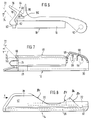
- FIG. 1 to 5 show a hand stuffing device 10 according to the invention for cigarette tubes (not shown), in particular for cigarette (filter) tubes (not shown) with a tobacco pressing chamber extending in the longitudinal direction of the hand stuffing device 10.
- the tobacco press chamber is formed by a housing 12 that is arranged in a longitudinally displaceable manner in a base part 14. Furthermore, the tobacco press chamber is delimited by a press bar 16 which is provided on a cover 18 which covers the housing 12 and is articulated on the housing 12. In addition, the tobacco press chamber is determined by a spoon 20 and an ejection slide 22 for ejecting a pressed tobacco rod from the tobacco press chamber via an opening 24 provided in the housing 12 into a cigarette (filter) sleeve.
- the discharge slide 22, which is fastened to the base part 12, carries the spoon 20.
- the base part 14 which is approximately U-shaped in cross section (cf. in particular FIG. 10), has two undercuts 26 for receiving two correspondingly shaped guide strips 28 of the housing 12. In this way, the housing 12 can be moved back and forth in the bottom part 14 exclusively in the longitudinal direction of the hand stuffing device 10.
- a latching device or the like is provided between the base part 14 and the housing 12 which is longitudinally displaceably received by the base part 14, which causes a certain stiffness at the beginning of the actual tamping process during the longitudinal displacement of the housing 12 in the base part 14 .
- the latching device here consists of at least one lateral projection 30 on at least one of the two guide strips 28 of the housing 12, which is just received by the undercut 26 of the base part 14 provided as a guide.
- the lateral projection 30, which is attached to at least one of the two guide strips 28 of the housing 12, can be snapped into a lateral recess 32, which is adapted to the latter, in the undercuts 26 of the base part 14 provided as a guide.
- the projection 30 is preferably attached to the guide bar 28 of the housing 12, as is the recess 32 in the undercut 26 of the base part 14 in the region of the end 36 of the cover 18 or base part 14 close to the articulation 34 between the cover 18 and the housing 12.
- the two side walls 38 of the bottom part 14, which is approximately U-shaped in cross section, in the region of the end 40 of the bottom part 14 opposite the articulation 34 between the cover 18 and the housing 12 with recessed grips 42 or the like.
- the recessed grips 42 or the like in particular offer a good hold to the thumb and the index finger of the user during the actual tamping process, that is to say during the longitudinal displacement of the housing 12 with the cover 18 hinged thereto, within the base part 14. This prevents slipping during the actual tamping process.
- recesses 46 are made in the bottom wall 44 connecting the two side walls 38 of the bottom part 14 to one another to save material and thus to reduce the weight of the hand tamping device 10 as a whole.
- the discharge slide 22 carrying the spoon 20 is mounted according to FIG. 8 in the region of the end 36 of the base part 14 near the linkage 34 between the cover 18 and the housing 12.
- the housing 12 has a filling opening 48 for filling the tobacco into the tobacco pressing chamber and an opening 24 for ejecting the pressed tobacco rod from the tobacco pressing chamber, to which a pipe socket 50 connects.
- the pipe socket 50 serves to accommodate the cigarette (filter) sleeve just to be filled with tobacco.
- Opening 24 and pipe socket 50 are arranged in the region of the end 40 of the base part 14 opposite the articulation 34 between the cover 18 and the housing 12.
- the articulation of the cover 18 to the housing 12 takes place here by means of two laterally outwardly extending circular projections 52 on the cover 18 which engage in correspondingly large bores 54 in the housing 12.
- the housing 12 has material cutouts 56, preferably in the region of the articulation 34 for reducing the weight of the hand stuffing device 10.
- the stiffening ribs 58 at the same time achieve a high stability and strength of the hand stuffing device 10.
- the hand stuffing device 10 comprises a clamping device 29, which holds the cigarette (filter) sleeve by clamping it to the pipe socket 50 arranged at the outlet of the tobacco press chamber, and a latching, snap-in or the like device 60 for releasably connecting the housing 12 and Lid 18.
- the latching, snap-in or similar device 60 has a latching lug 62 or the like which is arranged on the free end 64 of the lid 18 opposite the articulation 34 between the lid 18 and the housing 12 and with a latching projection 66 or provided on the housing 12 the like can be brought into engagement.
- the locking lug 62 or the like and the locking projection 66 or the like are essentially hook-shaped, the locking lug 62 or the like extending approximately in the direction of the linkage 34 between the cover 18 and the housing 12 and the locking projection 66 or the like in approximately the opposite direction.
- the latching lug 62 and the latching projection 66 come into contact in the case of mutual functional intervention via latching surfaces 68, 70.
- the two latching surfaces 68, 70 of latching lug 62 or latching projection 66 lie in a plane 72 which is perpendicular to the plane of the page and which extends the horizontal plane 74 which is perpendicular to the plane of the page at an angle ⁇ of 15 ° to 75 °, preferably at an angle ⁇ of 45 °, as shown in FIGS. 6 and 7 in detail.
- a locking trough for receiving the locking lug 62 or the like can also be provided.
- the latching trough extends corresponding to the latching lug 62 or the like approximately in the direction of the articulation 34 between the cover 18 and the housing 12.
- a latching trough (not shown) can be provided for receiving the latching projection 66 or the like. In this case, the locking trough extends accordingly Locking projection 66 or the like essentially in the opposite direction to the linkage 34.
- the locking lug 62 or the like is arranged on a resilient web 78 or the like, which in turn is connected to the free end 64 of the cover 18 via a further resilient web 75.
- the web 78 carrying the locking lug 62 or the like opens vertically into the spring-elastic web 75, as clearly shown in FIG. 6.
- Such a resilient design makes the engagement and disengagement of the latching lug 62 and the latching projection 66 in and apart from one another considerably easier. This is additionally achieved when the web 75 or the like extends in particular approximately parallel to that plane 72 in which the latching surfaces 68, 70 of the latching lug 62 and latching projection 66 are located.
- FIG. 6 moreover, at the free end 77 of the spring-elastic web 75 or the like, there is an actuating lever 76 for lifting the latching lug 62 from the latching projection 66 and thus for simplifying releasing and / or connecting the latching, snap-in or the like device 60 provided at the beginning of the tamping process or after completion of the same.
- the actuating lever 76 extends beyond the free end 64 of the cover 18, preferably approximately upwards.
- the actuating lever 76 runs essentially parallel to the plane 72 in which the latching surfaces 68, 70 lie and in particular in an extension of the further spring-elastic web 75.
- the web 80 or the like gives the user of the hand tamping device 10 a particularly large hold on the web 75 for disengaging the locking lug 62 and the locking projection 66 with the aid of the actuating lever 76.
- the actuating lever 76 and / or the rigid web 80 on the cover 18 and in this respect on the bottom part 12 which rotatably accommodates this, together with the recessed handles 42 on the bottom part 14, prevent the user from slipping off during the actual tamping process.
- the clamping device 59 consists of a clamping piece 82, which comes into close contact with the functional connection of the latching, snap-in or the like device 60 on the pipe socket 50.
- the cigarette (filter) sleeve is automatically clamped to the pipe socket 50 in this way, during the entire actual tamping process, i.e. during the entire ejection movement of the tobacco out of the tobacco press chamber.
- the clamping piece 82 is arranged at the free end 64 of the cover 16 opposite the articulation 34 between the cover 18 and the housing 12 near the latching, snap-in or similar device 60, preferably on the spring-elastic web 78 carrying the latching nose 62 or the like.
- the clamping effect to be achieved by the clamping piece 82 is further increased by the fact that the clamping piece 82 is designed to be resilient and possibly consists of soft plastic, rubber or the like.
- the side walls 38 of the base part 14 have material recesses 84 or the like in the central region or also in the region of the end 36 of the base part 14 adjacent to the articulation between cover 18 and housing 12.
- the material recesses 84 of the side walls 38 of the base part 14 are preferably provided in the region between the articulation 34 between the cover 18 and the housing 12 and the recessed handles 42 or the like.
- the material recesses 84 in the side walls 38 of the base part 14 extend in height up to close to the undercuts 26 of the bottom part 14.
- the material recesses 84 or the like in the two side walls 38 of the base part 14 result in a substantial reduction in the dead weight of the hand stuffing device 10.
Landscapes
- Cigarettes, Filters, And Manufacturing Of Filters (AREA)
- Manufacturing Of Cigar And Cigarette Tobacco (AREA)
- Packaging Of Annular Or Rod-Shaped Articles, Wearing Apparel, Cassettes, Or The Like (AREA)
Claims (16)
- Dispositif de remplissage manuel pour des tubes pour cigarettes, notamment pour des tubes de filtres de cigarettes, comportant une chambre de compression du tabac, qui s'étend dans la direction longitudinale du dispositif et qui est formée par un boîtier (12) disposé dans une partie de base (14), une barre de serrage (16) prévue sur un couvercle (18), qui recouvre le boîtier (12) et est articulé sur ce boîtier (12), une cuillère (20) ainsi qu'un poussoir d'éjection (22) pour éjecter un cordon comprimé de tabac hors de la chambre de compression du tabac par l'intermédiaire d'une ouverture (24), prévue dans le boîtier (12), à l'intérieur d'un tube (de filtre) de cigarette, et comportant un dispositif de serrage (59), qui maintient le tube (de filtre) de la cigarette sur un embout tubulaire disposé à la sortie de la chambre de compression du tabac, et un dispositif d'encliquetage, un dispositif à déclic ou analogue (60) pour relier de façon amovible le boîtier (12) et le couvercle (18) et qui comporte un bec d'encliquetage (62) ou analogue, qui est disposé sur une barrette (78) présentant l'élasticité d'un ressort, qui est reliée à l'extrémité libre (64) du couvercle (18), qui est située à l'opposé de l'articulation (34) entre le couvercle (18) et le boîtier (12), et est agencé essentiellement en forme de crochet et peut être amené à engrener avec un appendice saillant d'encliquetage (66) ou analogue, qui est prévu sur le boîtier (12), le bec d'encliquetage (62) ou analogue s'étendant approximativement en direction de l'articulation (34) entre le couvercle (18) et le boîtier (12), tandis que l'appendice saillant d'encliquetage (66) ou analogue s'étend approximativement dans la direction opposée, caractérisé en ce que
la barrette (78), qui inclut le bec d'encliquetage (62), est raccordée à l'extrémité libre (64) du couvercle (18) par l'intermédiaire d'une autre barrette (75) présentant l'élasticité d'un ressort et qui comporte, sur son extrémité libre (77), un levier d'actionnement (76) servant à écarter le bec d'encliquetage (62) de l'appendice saillant d'encliquetage (66) et par conséquent à détacher et/ou relier aisément le dispositif d'encliquetage, le dispositif à déclic ou analogue (60). - Dispositif de remplissage manuel selon la revendication 1, caractérisé en ce
que le levier d'actionnement (76) s'étend au-delà de l'extrémité libre (64) du couvercle (18), de préférence approximativement vers le haut. - Dispositif de remplissage manuel selon la revendication 2, caractérisé en ce
que les surfaces d'encliquetage (68,70), qui peuvent être amenées appliquées réciproquement l'une contre l'autre, du bec d'encliquetage (62) ou analogue et de l'appendice saillant d'encliquetage (66) ou analogue sont situées dans le plan (72), qui recoupe le plan horizontal (74) sous un angle α de 15° à 75° et de préférence de 45°. - Dispositif de remplissage manuel selon la revendication 2 et/ou 3, caractérisé en ce
que le levier d'actionnement (76) s'étend essentiellement parallèlement au plan (72), dans lequel sont situées les surfaces d'encliquetage (68,70), notamment dans le prolongement de l'autre barrette (75). - Dispositif de remplissage manuel selon au moins l'une des revendications 1 à 4, caractérisé en ce
que la barrette (78) ou analogue, qui porte le bec d'encliquetage (62) ou analogue, se raccorde perpendiculairement à la barrette (75) présentant l'élasticité d'un ressort ou analogue. - Dispositif de remplissage manuel selon au moins l'une des revendications 1 à 5, caractérisé en ce
qu'une autre barrette (80) ou analogue, qui s'étend essentiellement verticalement vers le haut et est agencée en étant rigide dans une large mesure, est prévue à proximité de la barrette (75) ou analogue, sur l'extrémité libre (64) du couvercle (18). - Dispositif de remplissage manuel selon au moins l'une des revendications 1 à 6, caractérisé en ce
que le dispositif de serrage (59) est constitué par un élément de serrage (82), qui est disposé sur l'extrémité libre (64) du couvercle (18), située à l'opposé de l'articulation (34) entre le couvercle (18) et le boîtier (12), à proximité du dispositif d'encliquetage, du dispositif à déclic ou analogue (60), notamment sur la barrette (78) ou analogue, qui porte le bec d'encliquetage (62) ou analogue. - Dispositif de remplissage manuel selon la revendication 7, caractérisé en ce
que l'élément de serrage (82) est agencé de manière à présenter l'élasticité d'un ressort, et notamment est réalisé en matière plastique molle, en caoutchouc mou ou analogue. - Dispositif de remplissage manuel selon au moins l'une des revendications 1 à 8, caractérisé en ce
que le boîtier (12) est disposé de manière à être déplaçable longitudinalement dans la partie de base (14), le poussoir d'éjection (22) étant fixé sur la partie de base (14) et retenant la cuillère (20). - Dispositif de remplissage manuel selon au moins l'une des revendications 1 à 9, caractérisé en ce
qu'un dispositif d'encliquetage ou analogue est prévu entre la partie de base (14) et le boîtier (12) logé de manière à être déplaçable longitudinalement dans la partie de base (14). - Dispositif de remplissage manuel selon la revendication 10, caractérisé en ce que
le dispositif d'encliquetage est constitué par au moins un appendice saillant, qui est disposé sur une barrette de guidage (28) du boîtier (12), de préférence dans la zone de l'extrémité (36) du couvercle (18), qui est proche de l'articulation (34) entre le couvercle (18) et le boîtier (12), la barrette de guidage étant logée dans une partie en contre-dépouille (26), prévue en tant que guide, de la partie de base (14). - Dispositif de remplissage manuel selon la revendication 11, caractérisé en ce
que l'appendice saillant (30), disposé sur la barrette de guidage (28) du boîtier (12), peut être encliquetée dans un évidement (32) adapté à cette partie saillante, de préférence dans la zone de l'extrémité (36) de la partie de base (14), qui est proche de l'articulation (34) présente entre le couvercle (18) et le boîtier (12), évidement qui est formé dans la partie en contre-dépouille (26), prévue en tant que guide, de la partie de base (14). - Dispositif de remplissage manuel selon au moins l'une des revendications 1 à 12, caractérisé en ce
que la partie de base (14) est agencée approximativement en forme de U en coupe transversale, les deux parois latérales (38) comportant, dans la zone de l'extrémité (40) du couvercle (18), qui est située à l'opposé de l'articulation (34) entre le couvercle (18) et le boîtier (12), des évidements de préhension (42) ou analogues. - Dispositif de remplissage manuel selon au moins l'une des revendications 1 à 13, caractérisé en ce
que les parois latérales (38) de la partie de base (14) possèdent des évidements (84) ou analogues, dans la zone de l'extrémité (36), voisine de l'articulation (34) entre le couvercle (18) et le boîtier (12), de la partie de base (14). - Dispositif de remplissage manuel selon la revendication 13 et/ou 14, caractérisé en ce
que les évidements (84) dans les parois latérales (38) sont prévus, notamment de manière à s'étendre continûment, à partir de la partie de base (14) dans la zone comprise entre l'articulation (34) du couvercle (18) et du boîtier (12) et les évidements de préhension (42) ou analogues. - Dispositif de remplissage manuel selon au moins l'une des revendications 1 à 15, caractérisé en ce
que la partie de base (14) comporte d'autres ouvertures (46) et que le boîtier (12) comporte des évidements (56).
Applications Claiming Priority (4)
| Application Number | Priority Date | Filing Date | Title |
|---|---|---|---|
| DE4205217 | 1992-02-20 | ||
| DE4205217 | 1992-02-20 | ||
| DE4207196A DE4207196C2 (de) | 1992-02-20 | 1992-03-06 | Handstopfvorrichtung für Zigarettenhülsen, insbesondere für Zigarettenfilterhülsen |
| DE4207196 | 1992-03-06 |
Publications (2)
| Publication Number | Publication Date |
|---|---|
| EP0556860A1 EP0556860A1 (fr) | 1993-08-25 |
| EP0556860B1 true EP0556860B1 (fr) | 1996-05-15 |
Family
ID=25912036
Family Applications (1)
| Application Number | Title | Priority Date | Filing Date |
|---|---|---|---|
| EP93102692A Expired - Lifetime EP0556860B1 (fr) | 1992-02-20 | 1993-02-19 | Dispositif de remplissage manuel pour tubes à cigarette, notamment pour tube pour cigarettes à filtre |
Country Status (11)
| Country | Link |
|---|---|
| US (1) | US5450861A (fr) |
| EP (1) | EP0556860B1 (fr) |
| AT (1) | ATE137920T1 (fr) |
| CA (1) | CA2089782C (fr) |
| CZ (1) | CZ283382B6 (fr) |
| DE (2) | DE4207196C2 (fr) |
| DK (1) | DK0556860T3 (fr) |
| FI (1) | FI97019C (fr) |
| HU (1) | HUT69657A (fr) |
| NO (1) | NO177213C (fr) |
| SK (1) | SK280341B6 (fr) |
Families Citing this family (19)
| Publication number | Priority date | Publication date | Assignee | Title |
|---|---|---|---|---|
| DE4207196C2 (de) * | 1992-02-20 | 1993-12-16 | Efka Werke Kiehn Gmbh Fritz | Handstopfvorrichtung für Zigarettenhülsen, insbesondere für Zigarettenfilterhülsen |
| CA2239289A1 (fr) * | 1995-12-04 | 1997-06-12 | Efka-Werke Fritz Kiehn Gmbh | Machine manuelle pour remplir des tubes de cigarettes, notamment des tubes de cigarettes-filtres, avec une chambre de compactage du tabac a longueur variable |
| FR2825900B1 (fr) * | 2001-06-14 | 2003-12-12 | Republic Technologies Na Llc | Machine a garnir des tubes de cigarettes a maintien ameliore en position fermee |
| US20060096604A1 (en) * | 2002-11-21 | 2006-05-11 | Cousins Distributing, Inc. | Device for filling a cigarette tube with a metered amount of tobacco |
| ATE386447T1 (de) * | 2002-11-21 | 2008-03-15 | Cousins Distributing Inc | Gerät zum füllen einer zigarettenhülse mit einer abgemessenen menge tabak |
| DE102004047407B3 (de) * | 2004-09-28 | 2006-04-13 | Burk, Jörg | Automatisches Zigaretten-Selbstverfertigungsgerät |
| US7565818B2 (en) * | 2005-06-01 | 2009-07-28 | R.J. Reynolds Tobacco Company | Apparatus and methods for manufacturing cigarettes |
| US20060272653A1 (en) * | 2005-06-01 | 2006-12-07 | Thomas Timothy F | Apparatus and methods for manufacturing cigarettes |
| US7597105B2 (en) * | 2005-06-01 | 2009-10-06 | R.J. Reynolds Tobacco Co. | Apparatus for manufacturing cigarettes |
| US7325382B2 (en) * | 2005-06-01 | 2008-02-05 | R. J. Reynolds Tobacco Company | Method and apparatus for loading finished cigarettes into package |
| WO2006130367A2 (fr) * | 2005-06-01 | 2006-12-07 | R. J. Reynolds Tobacco Company | Appareil et procede de fabrication de cigarettes |
| US7537013B2 (en) * | 2005-06-01 | 2009-05-26 | R.J. Reynolds Tobacco Company | Apparatus for manufacturing cigarettes |
| DE102005028990B4 (de) * | 2005-06-21 | 2007-12-06 | Burk, Jörg | Automatisches Zigarettenstopfgerät |
| US7665469B1 (en) * | 2006-06-15 | 2010-02-23 | Behyar Behipour | Cigarette and tobacco packing machine |
| USD547002S1 (en) * | 2007-02-02 | 2007-07-17 | Republic Tobacco L.P. | Hand-held apparatus for injecting tobacco into paper tubes |
| DE102007023776A1 (de) | 2007-05-22 | 2008-12-11 | Schönhoff, Boris | Zigarettenstopfmaschine |
| CA129904S (en) * | 2008-09-26 | 2009-12-15 | Gizeh Raucherbedarf Gmbh | Filter tube injector |
| CN106579547B (zh) * | 2016-12-15 | 2017-12-01 | 上海理工大学 | 实验室用小型手工卷烟装置 |
| USD952938S1 (en) | 2020-08-18 | 2022-05-24 | Republic Brands L.P. | Cigarette-making machine |
Family Cites Families (6)
| Publication number | Priority date | Publication date | Assignee | Title |
|---|---|---|---|---|
| DE211462C (fr) * | ||||
| BE755536A (fr) * | 1969-09-09 | 1971-02-01 | Gizeh Werk Gmbh | Appareil pour confectionner les cigarettes |
| DE1945498C3 (de) * | 1969-09-09 | 1975-10-30 | Gizeh-Werk Gmbh, 5275 Bergneustadt | Vorrichtung zum Stopfen vorgefertigter Zigarettenhülsen |
| US3741220A (en) * | 1970-03-02 | 1973-06-26 | Gizeh Werk Gmbh | Cigarette making appliance |
| DE2021738C3 (de) * | 1970-05-04 | 1973-11-22 | Gizeh Werk Gmbh | Zigarettenfertiger |
| DE4207196C2 (de) * | 1992-02-20 | 1993-12-16 | Efka Werke Kiehn Gmbh Fritz | Handstopfvorrichtung für Zigarettenhülsen, insbesondere für Zigarettenfilterhülsen |
-
1992
- 1992-03-06 DE DE4207196A patent/DE4207196C2/de not_active Expired - Fee Related
-
1993
- 1993-02-17 SK SK99-93A patent/SK280341B6/sk unknown
- 1993-02-17 HU HU9300430A patent/HUT69657A/hu unknown
- 1993-02-18 CA CA002089782A patent/CA2089782C/fr not_active Expired - Fee Related
- 1993-02-18 NO NO930568A patent/NO177213C/no not_active IP Right Cessation
- 1993-02-19 DE DE59302542T patent/DE59302542D1/de not_active Expired - Fee Related
- 1993-02-19 US US08/020,201 patent/US5450861A/en not_active Expired - Fee Related
- 1993-02-19 FI FI930750A patent/FI97019C/fi active
- 1993-02-19 EP EP93102692A patent/EP0556860B1/fr not_active Expired - Lifetime
- 1993-02-19 CZ CZ93247A patent/CZ283382B6/cs not_active IP Right Cessation
- 1993-02-19 AT AT93102692T patent/ATE137920T1/de not_active IP Right Cessation
- 1993-02-19 DK DK93102692.6T patent/DK0556860T3/da active
Also Published As
| Publication number | Publication date |
|---|---|
| FI97019B (fi) | 1996-06-28 |
| EP0556860A1 (fr) | 1993-08-25 |
| FI97019C (fi) | 1996-10-10 |
| FI930750A0 (fi) | 1993-02-19 |
| DK0556860T3 (da) | 1996-06-03 |
| NO177213C (no) | 1995-08-09 |
| US5450861A (en) | 1995-09-19 |
| DE59302542D1 (de) | 1996-06-20 |
| FI930750A7 (fi) | 1993-08-21 |
| HU9300430D0 (en) | 1993-05-28 |
| CZ24793A3 (en) | 1993-11-17 |
| CZ283382B6 (cs) | 1998-04-15 |
| NO930568L (no) | 1993-08-23 |
| HUT69657A (en) | 1995-09-28 |
| DE4207196C2 (de) | 1993-12-16 |
| NO930568D0 (no) | 1993-02-18 |
| NO177213B (no) | 1995-05-02 |
| DE4207196A1 (de) | 1993-08-26 |
| CA2089782A1 (fr) | 1993-08-21 |
| CA2089782C (fr) | 1999-05-18 |
| ATE137920T1 (de) | 1996-06-15 |
| SK9993A3 (en) | 1994-01-12 |
| SK280341B6 (sk) | 1999-12-10 |
Similar Documents
| Publication | Publication Date | Title |
|---|---|---|
| EP0556860B1 (fr) | Dispositif de remplissage manuel pour tubes à cigarette, notamment pour tube pour cigarettes à filtre | |
| EP0865242B1 (fr) | Machine manuelle pour remplir des tubes de cigarettes, notamment des tubes de cigarettes-filtres, avec une chambre de compactage du tabac a longueur variable | |
| DE69312151T2 (de) | Pipettiervorrichtung mit einem Abwerfer für Pipettenspitzen | |
| DE19522349C2 (de) | Staubsauger für Doppelbetrieb | |
| DE202008014111U1 (de) | Abisolierzange | |
| DE2549477B2 (de) | Pipettiervorrichtung | |
| DE3128595A1 (de) | Gestell aus loesbar verbindbaren profilstangen | |
| EP0105176A2 (fr) | Elément de liaison pour un câble de changement de vitesse | |
| EP0144971B1 (fr) | Dispositif de remplissage manuel pour tubes à cigarettes | |
| DE102011107319B4 (de) | Flachwischer und Trägerplatte dafür | |
| DE7836598U1 (de) | Vorrichtung zur fuellung vorgeformter zigaretten-papierroehrchen mit tabak von hand | |
| DE19653897B4 (de) | Führungsanordnung für ein Türelement | |
| EP0806187B1 (fr) | Applicateur | |
| EP0074525B1 (fr) | Instrument de nettoyage plurifonctionnel | |
| DE4434065C1 (de) | Reinigungseinrichtung | |
| DE2526740C2 (de) | Handgerät zum Absaugen von festen, flüssigen oder geschmolzenen Partikeln | |
| DE2839780C2 (de) | Schneidgerät, insbesondere Gras- oder Heckenschere | |
| DE10316633A1 (de) | Säbelsäge mit Führungsvorrichtung | |
| DE2931537C2 (de) | Haushalts-Müllverdichter | |
| DE3039328A1 (de) | Scharnierarm mit befestigungsplatte | |
| EP0074042A1 (fr) | Dispositif manuel pour remplir les tubes de cigarette | |
| DE29707813U1 (de) | Gerät zum Abnehmen einer Kanüleneinheit bzw. Kanülenschutzeinheit | |
| EP0464168A1 (fr) | Systeme de poignee pour valise a roulettes ou analogue | |
| DE19924015A1 (de) | Zahnseidespender | |
| DE9106427U1 (de) | Heftzange |
Legal Events
| Date | Code | Title | Description |
|---|---|---|---|
| PUAI | Public reference made under article 153(3) epc to a published international application that has entered the european phase |
Free format text: ORIGINAL CODE: 0009012 |
|
| AK | Designated contracting states |
Kind code of ref document: A1 Designated state(s): AT BE DE DK FR IT LU NL SE |
|
| 17P | Request for examination filed |
Effective date: 19940223 |
|
| 17Q | First examination report despatched |
Effective date: 19950628 |
|
| GRAH | Despatch of communication of intention to grant a patent |
Free format text: ORIGINAL CODE: EPIDOS IGRA |
|
| GRAA | (expected) grant |
Free format text: ORIGINAL CODE: 0009210 |
|
| AK | Designated contracting states |
Kind code of ref document: B1 Designated state(s): AT BE DE DK FR IT LU NL SE |
|
| REF | Corresponds to: |
Ref document number: 137920 Country of ref document: AT Date of ref document: 19960615 Kind code of ref document: T |
|
| REG | Reference to a national code |
Ref country code: DK Ref legal event code: T3 |
|
| REF | Corresponds to: |
Ref document number: 59302542 Country of ref document: DE Date of ref document: 19960620 |
|
| ITF | It: translation for a ep patent filed | ||
| ET | Fr: translation filed | ||
| PLBE | No opposition filed within time limit |
Free format text: ORIGINAL CODE: 0009261 |
|
| STAA | Information on the status of an ep patent application or granted ep patent |
Free format text: STATUS: NO OPPOSITION FILED WITHIN TIME LIMIT |
|
| 26N | No opposition filed | ||
| PGFP | Annual fee paid to national office [announced via postgrant information from national office to epo] |
Ref country code: AT Payment date: 20000218 Year of fee payment: 8 Ref country code: LU Payment date: 20000218 Year of fee payment: 8 |
|
| PG25 | Lapsed in a contracting state [announced via postgrant information from national office to epo] |
Ref country code: LU Free format text: LAPSE BECAUSE OF NON-PAYMENT OF DUE FEES Effective date: 20010219 Ref country code: AT Free format text: LAPSE BECAUSE OF NON-PAYMENT OF DUE FEES Effective date: 20010219 |
|
| PGFP | Annual fee paid to national office [announced via postgrant information from national office to epo] |
Ref country code: NL Payment date: 20011220 Year of fee payment: 10 |
|
| PGFP | Annual fee paid to national office [announced via postgrant information from national office to epo] |
Ref country code: DE Payment date: 20011228 Year of fee payment: 10 |
|
| PGFP | Annual fee paid to national office [announced via postgrant information from national office to epo] |
Ref country code: BE Payment date: 20020125 Year of fee payment: 10 |
|
| PGFP | Annual fee paid to national office [announced via postgrant information from national office to epo] |
Ref country code: FR Payment date: 20020129 Year of fee payment: 10 |
|
| PGFP | Annual fee paid to national office [announced via postgrant information from national office to epo] |
Ref country code: DK Payment date: 20020212 Year of fee payment: 10 |
|
| PGFP | Annual fee paid to national office [announced via postgrant information from national office to epo] |
Ref country code: SE Payment date: 20020221 Year of fee payment: 10 |
|
| PG25 | Lapsed in a contracting state [announced via postgrant information from national office to epo] |
Ref country code: SE Free format text: LAPSE BECAUSE OF NON-PAYMENT OF DUE FEES Effective date: 20030220 |
|
| PG25 | Lapsed in a contracting state [announced via postgrant information from national office to epo] |
Ref country code: BE Free format text: LAPSE BECAUSE OF NON-PAYMENT OF DUE FEES Effective date: 20030228 |
|
| PG25 | Lapsed in a contracting state [announced via postgrant information from national office to epo] |
Ref country code: DK Free format text: LAPSE BECAUSE OF NON-PAYMENT OF DUE FEES Effective date: 20030828 |
|
| PG25 | Lapsed in a contracting state [announced via postgrant information from national office to epo] |
Ref country code: NL Free format text: LAPSE BECAUSE OF NON-PAYMENT OF DUE FEES Effective date: 20030901 |
|
| PG25 | Lapsed in a contracting state [announced via postgrant information from national office to epo] |
Ref country code: DE Free format text: LAPSE BECAUSE OF NON-PAYMENT OF DUE FEES Effective date: 20030902 |
|
| EUG | Se: european patent has lapsed | ||
| REG | Reference to a national code |
Ref country code: DK Ref legal event code: EBP |
|
| PG25 | Lapsed in a contracting state [announced via postgrant information from national office to epo] |
Ref country code: FR Free format text: LAPSE BECAUSE OF NON-PAYMENT OF DUE FEES Effective date: 20031031 |
|
| NLV4 | Nl: lapsed or anulled due to non-payment of the annual fee |
Effective date: 20030901 |
|
| REG | Reference to a national code |
Ref country code: FR Ref legal event code: ST |
|
| PG25 | Lapsed in a contracting state [announced via postgrant information from national office to epo] |
Ref country code: IT Free format text: LAPSE BECAUSE OF NON-PAYMENT OF DUE FEES;WARNING: LAPSES OF ITALIAN PATENTS WITH EFFECTIVE DATE BEFORE 2007 MAY HAVE OCCURRED AT ANY TIME BEFORE 2007. THE CORRECT EFFECTIVE DATE MAY BE DIFFERENT FROM THE ONE RECORDED. Effective date: 20050219 |