EP0557095A2 - Dispositif de détection de vecteur de mouvement - Google Patents
Dispositif de détection de vecteur de mouvement Download PDFInfo
- Publication number
- EP0557095A2 EP0557095A2 EP93301198A EP93301198A EP0557095A2 EP 0557095 A2 EP0557095 A2 EP 0557095A2 EP 93301198 A EP93301198 A EP 93301198A EP 93301198 A EP93301198 A EP 93301198A EP 0557095 A2 EP0557095 A2 EP 0557095A2
- Authority
- EP
- European Patent Office
- Prior art keywords
- image
- movement vector
- detecting
- edges
- movement
- Prior art date
- Legal status (The legal status is an assumption and is not a legal conclusion. Google has not performed a legal analysis and makes no representation as to the accuracy of the status listed.)
- Granted
Links
Images


Classifications
-
- G—PHYSICS
- G01—MEASURING; TESTING
- G01S—RADIO DIRECTION-FINDING; RADIO NAVIGATION; DETERMINING DISTANCE OR VELOCITY BY USE OF RADIO WAVES; LOCATING OR PRESENCE-DETECTING BY USE OF THE REFLECTION OR RERADIATION OF RADIO WAVES; ANALOGOUS ARRANGEMENTS USING OTHER WAVES
- G01S3/00—Direction-finders for determining the direction from which infrasonic, sonic, ultrasonic or electromagnetic waves, or particle emission, not having a directional significance, are being received
- G01S3/78—Direction-finders for determining the direction from which infrasonic, sonic, ultrasonic or electromagnetic waves, or particle emission, not having a directional significance, are being received using electromagnetic waves other than radio waves
- G01S3/782—Systems for determining direction or deviation from predetermined direction
- G01S3/785—Systems for determining direction or deviation from predetermined direction using adjustment of orientation of directivity characteristics of a detector or detector system to give a desired condition of signal derived from that detector or detector system
- G01S3/786—Systems for determining direction or deviation from predetermined direction using adjustment of orientation of directivity characteristics of a detector or detector system to give a desired condition of signal derived from that detector or detector system the desired condition being maintained automatically
- G01S3/7864—T.V. type tracking systems
-
- G—PHYSICS
- G06—COMPUTING OR CALCULATING; COUNTING
- G06T—IMAGE DATA PROCESSING OR GENERATION, IN GENERAL
- G06T7/00—Image analysis
- G06T7/20—Analysis of motion
- G06T7/223—Analysis of motion using block-matching
-
- G—PHYSICS
- G06—COMPUTING OR CALCULATING; COUNTING
- G06T—IMAGE DATA PROCESSING OR GENERATION, IN GENERAL
- G06T7/00—Image analysis
- G06T7/20—Analysis of motion
- G06T7/223—Analysis of motion using block-matching
- G06T7/238—Analysis of motion using block-matching using non-full search, e.g. three-step search
-
- H—ELECTRICITY
- H04—ELECTRIC COMMUNICATION TECHNIQUE
- H04N—PICTORIAL COMMUNICATION, e.g. TELEVISION
- H04N23/00—Cameras or camera modules comprising electronic image sensors; Control thereof
- H04N23/60—Control of cameras or camera modules
- H04N23/68—Control of cameras or camera modules for stable pick-up of the scene, e.g. compensating for camera body vibrations
- H04N23/681—Motion detection
- H04N23/6811—Motion detection based on the image signal
-
- H—ELECTRICITY
- H04—ELECTRIC COMMUNICATION TECHNIQUE
- H04N—PICTORIAL COMMUNICATION, e.g. TELEVISION
- H04N23/00—Cameras or camera modules comprising electronic image sensors; Control thereof
- H04N23/60—Control of cameras or camera modules
- H04N23/68—Control of cameras or camera modules for stable pick-up of the scene, e.g. compensating for camera body vibrations
- H04N23/682—Vibration or motion blur correction
- H04N23/683—Vibration or motion blur correction performed by a processor, e.g. controlling the readout of an image memory
-
- H—ELECTRICITY
- H04—ELECTRIC COMMUNICATION TECHNIQUE
- H04N—PICTORIAL COMMUNICATION, e.g. TELEVISION
- H04N5/00—Details of television systems
- H04N5/14—Picture signal circuitry for video frequency region
- H04N5/144—Movement detection
-
- H—ELECTRICITY
- H04—ELECTRIC COMMUNICATION TECHNIQUE
- H04N—PICTORIAL COMMUNICATION, e.g. TELEVISION
- H04N5/00—Details of television systems
- H04N5/14—Picture signal circuitry for video frequency region
- H04N5/144—Movement detection
- H04N5/145—Movement estimation
-
- G—PHYSICS
- G06—COMPUTING OR CALCULATING; COUNTING
- G06T—IMAGE DATA PROCESSING OR GENERATION, IN GENERAL
- G06T2207/00—Indexing scheme for image analysis or image enhancement
- G06T2207/10—Image acquisition modality
- G06T2207/10016—Video; Image sequence
Definitions
- the present invention relates to a movement vector detecting device, and more particularly to a device for detecting a movement vector from an image signal.
- the movement vector detecting device has been employed in the image encoding device or the image vibration compensating device.
- For movement vector detection by image signal processing there have been known a time-space inclination method disclosed for example in the U.S. Patent No. 3,890,462 and in the Japanese Patent Publication No. 60-46878, a correlation method based on calculation of correlation, and a block matching method.
- the amount of movement is calculated from the difference d in luminance between frames (or fields) and the difference ⁇ between pixels in a frame.
- the image signal of a moving image is an average in time with a field cycle time, and that the edge becomes less sharp and the difference ⁇ in luminance among pixels becomes smaller as the amount of movement of image becomes larger.
- the amount of movement is defined by d/ ⁇ , namely the difference d in luminance among frames or fields, normalized by the difference ⁇ in luminance among pixels.
- the block matching method consists of dividing the input image signal into blocks of a suitable size (for example 8 pixels by 8 lines), comparing each block with the pixels of a predetermined area in a preceding frame (or field) and determining the most resembling position by laterally moving the comparing position within the image frame. For example there is searched a position where the sum, within the block, of absolute difference of pixels between the frames (or fields), and the movement vector is represented by the relative displacement of the most resembling blocks.
- a suitable size for example 8 pixels by 8 lines
- the unit block for movement vector detection contains only low spatial frequencies and lacks characteristic pattern (such as sky, water surface, white wall or asphalt surface), or in case said unit block contains a plurality of similar characteristic points with a high spatial frequency (such as flower field, leaves of a tree or a door with grid pattern), or in case an object having the edge only in a specified direction (such as an oblong rod) moves along the direction of said edge.
- a high-efficiency image encoding device or an image vibration compensating device is operated according to an erroneous movement vector or a movement vector involving a large error, the precision of encoding or compensation is significantly deteriorated, and the image quality may become even worse by such encoding or compensation.
- the present invention is to resolve the above-mentioned drawbacks of the prior art, and is concerned with providing a movement vector detecting device capable of accurately detecting the movement regardless of the state of the image.
- the present invention is also concerned with providing a vibration compensating device capable of accurately detecting the movement vector of an object image regardless of the pattern thereof, and enabling the realisation of optimum movement compensating characteristics without erroneous operations.
- the present invention is additionally concerned with providing a camera constantly capable of accurate compensation for vibration regardless of the state of the object to be photographed.
- the present invention comprises a movement vector detecting device comprising movement vector detecting means for dividing the image frame into plural blocks and detecting the movement vector in each block; edge detecting means for detecting the number of edges of the image in each block; and evaluation means for evaluating the reliability of the movement vector value detected by said movement vector detecting means, based on the number of edges detected by said edge detecting means.
- a vibration compensating device comprising movement vector detecting means for dividing the image frame into plural blocks and detecting the movement vector in each block; edge detecting means for detecting the number of edges of the image in each of said blocks; calculation means for varying the weight on the movement vector value detected by said movement vector detecting means, based on the number of edges detected by said edge detecting means, thereby calculating the movement vector evaluation value of the image, and compensation means for compensating the image movement based on the output of said calculation means.
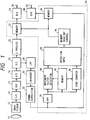
- Fig. 1 is a block diagram of a video camera with an antivibration devices, constituting an embodiment of the present invention.
- the vibration of image is suppressed by storing the phototaken image signal of an image frame in an image memory, and controlling the read-out range from said image memory according to the detected movement vector.
- an image pickup device 12 converts an object image, formed by a phototaking lens 10, into an electrical signal.
- the image pickup device 12 releases a line-sequential color difference image signal.
- the output of said image pickup device 12 is supplied, through a sample hold (S/H) circuit 14, to an AGC (automatic gain control) circuit 16. Which automatically regulates the gain of the output signal of the S/H circuit 14 and of which output is converted into a digital signal by an A/D converting circuit 18.
- a Y/C separation circuit 20 is composed of two 1H delay lines and an adder for adding the input and a 2H delayed signal.
- the output of said adder is supplied to a C process circuit 22 constituting a color signal processing circuit, while a 1H delayed signal is supplied to a low-pass filter (LPF) 28 of a luminance signal processing system.
- the C process circuit 22 generates a chroma signal from the output of the Y/C separation circuit 20, and its output is temporarily stored in a memory 23 in an image vibration suppressing circuit 33 to be explained later.
- the LPF 28 eliminates the carrier component of the line-sequential color difference signal, from the signal supplied from the Y/C separation circuit 20.
- the output of the LPF 28 is supplied to an enhancer 30 for edge enhancement.
- the enhancer 30 normally adds, to the input signal, a secondary differentiated signal thereof.
- a gamma correction circuit 32 avoids the saturation in the high-light area and widens the dynamic range, on the output of the enhancer 30.
- the ordinary luminance signal process is completed in this manner, and the output of the gamma correction circuit is supplied to the image vibration suppressing circuit 33.
- the output of the gamma correction circuit 32 is supplied to a field (or frame) memory 34 and a band-pass filter (BPF) 36 consisting of a spatial frequency filter.
- a memory 34 temporarily stores the entered luminance signal.
- the BPF 36 extracts, from the output of the gamma correction circuit 32, spatial frequency components useful for movement vector detection. Thus the low and high spatial frequency components are eliminated from the image signal.
- the BPF 36 releases the code bit of the digital output signal of the gamma correction circuit 32. This corresponds to the binarization of the luminance signal, employing the DC level as the threshold value.
- the circuits succeeding to the BPF 36 can be composed of 1-bit processing system and can therefore be compactized.
- the output of the BPF is supplied to a movement vector detecting circuit 38, a memory 40 serving as 1-field time delay means and an edge counter 42.
- Said movement vector detecting circuit 38 also receives the signal of the preceding field from the memory 40, and detects the movement vector by the calculation according to the time-space inclination method or by the correlation calculation, based on the current field and the preceding field.
- the edge counter 42 counts the number of edges in the horizontal and vertical directions contained in each unit block for movement vector detection in the movement vector detecting circuit 38. More specifically, it detects the inversion of output of the BPF 36, by taking exclusive logic sum between the neighboring pixels.
- the movement vector (horizontal and vertical components) detected by the movement vector detecting circuit 38, and the number of edges in each block, detected by the edge counter 42, are supplied to an operation circuit 44 composed of a microcomputer, which evaluates the reliability of the movement vector in each block, by the number of edges in the same block. More specifically, the movement vectors respectively detected in the blocks constituting the detection units for the movement vector are weighted by the number of detected edges, and the movement vector for the entire image frame is detected, as will be explained later in more details.
- the operation circuit 44 supplies the calculated movement vector to a memory read-out control circuit 46, which, in response, controls read-out control circuit 46, which, in response, controls the read-out positions of the memories 23, 34 so as to cancel the image movement.
- the chroma signal read from the memory 23 is converted into an analog signal by a D/A converter 24, and is released from an output terminal 26. Also the luminance signal read from the memory 34 is converted into an analog signal by a D/A converter 48, and is released from an output terminal 50. In this manner, the image signal with suppressed image vibration is released from said output terminals 26, 50.
- Fig. 2 shows an orthogonal coordinate system representing the spatial frequency area, wherein the abscissa fx indicates the horizontal spatial frequency while the ordinate indicates the vertical spatial frequency. Pattern shown on the coordinate system indicates a binary pattern corresponding to the spatial frequency of the illustrated position. In general, the spatial frequency distribution of an image assumes a cross-shape pattern with limited diagonal components.
- the component of movement in a direction orthogonal to the direction of edge (tangential direction) of the image can be detected with satisfactory precision, but the component in the direction of edge is difficult to detect, with low reliability of detected value. Also in the direction orthogonal to the edge, the reliability becomes low if the periodical pattern exists in said direction, because of the possibility of mismatching.
- the x component of the movement vector is detectable, but y component is not detectable.
- a rough pattern as shown in Fig. 3A with a block size of 10 x 10 pixels, there are observed 10 edges in the x-direction and 0 edges in the y-direction. In such case, the detected value of y-component of the movement vector is unreliable.
- the detected value in the y-direction is unreliable because there is no edge in the y-direction as in the case of Fig. 3A.
- the reliability becomes also low in the x-direction, because of the possible mismatching resulting from the periodicity.
- the detected value in the x-direction is unreliable because of too many edges, and the detected value in the y-direction is also unreliable because of absence of edge.
- Fig. 4 shows an example of the weighting function (evaluating function) for the number of detected edges, wherein n indicates the block size in the x- and y-directions.
- the maximum number of edges in a block of n x n pixels is n(n - 1).
- the operation circuit 44 evaluates the x- and y-components of the detected movement vectors, individually utilizing said weighting function, and effects a process of averaging similar movement vectors with weights in a closed output area and eliminating the movement vectors of low reliability.
- the edge is judged from a particular spatial frequency component extracted by the two-dimensional BPF 36, but it is naturally possible also to count the edges of boundaries or contours by extracting edge information from multi-value image signal.
- Direct edge detection from the luminance signal can be achieved by the zero-crossing method, in which the edge is detected by secondary differentiation of the luminance signal, as detailedly reported by D. Marr and E. Hildreth in "Theory of Edge Detection", Proceeding of the Roval Society of London, B207, 1980, pp187 - 217.
- Fig. 5A shows an edge part of an image
- Fig. 5B shows a differential of the signal shown in Fig. 5A
- Fig. 5C shows a differential of the signal shown in Fig. 5B, or a second-order differential of the signal shown in Fig. 5A.
- the wave form of said second-order differential shown in Fig. 5C inverts the sign at the center of the edge, and said sign inverting point is called zero crossing point.
- the edges can be detected in the horizontal and vertical directions, by effecting second-order differentiation in said directions.
- the reliability of the detected movement vector can be evaluated also by the edges detected by such zero crossing method.
- edge detectors There have also been proposed other types of edge detectors, which are likewise applicable to the present invention.
- Roberts' edge detector reported by L. G. Roberts, "machine perception of three-dimensional solids", in Optical and Electro-optical Information Processing, and J. T. Tippett et al. (eds,), MIT Press, Cambridge, Mass., 1965, pp.159 -197
- Prewitt's edge detector reported by J. M. S. Prewitt, "object enhancement and extraction” in Picture Processing and Psychopictorics; and B. S. Lipkine and A. Rosenfeld (eds.), Academic Press, New York, 1970.
- the reliability of the movement vector is evaluated by the total sum of the number of edges in the x- or y-direction, but the above-mentioned evaluation function may also be applied to a horizontal or vertical scanning line in each block. The meaning of such method will be explained with reference to Fig. 6.
- Fig. 6 shows an example of binary pattern, with a block size of 10 x 10 pixels, and the distributions of the number of edges in the x-and y-direction are shown by histograms illustrated outside of said pattern.
- the pattern shown in Fig. 6 has edges repeating in the y-direction with a short cycle, so that it is difficult to exactly detect the y-component of the movement vector.
- this pattern has 10 edges in the x-direction and 9 edges in the y-direction, so that the reliability is high in the evaluation by the total sum of the number of edges.
- the aforementioned evaluation function may be applied to each horizontal or vertical scanning line.
- the number of edges present on a horizontal or vertical scanning line is between 0 and (n - 1). Therefore, the evaluation (weight) is made lower in case the number of detected edges is 0 or (n - 1) or close thereto. With this method, the y-component of the movement vector detected in this block is evaluated low.
- the reliability of plural detected movement vector values is evaluated by the numbers of edges detected in respective blocks, so that a movement vector of high reliability and high precision can be obtained in the entire image area or in a suitable closed area. Consequently there can be obtained satisfactory performance in the moving image encoding device or in the image vibration compensating device.
Landscapes
- Engineering & Computer Science (AREA)
- Multimedia (AREA)
- Signal Processing (AREA)
- Physics & Mathematics (AREA)
- General Physics & Mathematics (AREA)
- Theoretical Computer Science (AREA)
- Computer Vision & Pattern Recognition (AREA)
- Radar, Positioning & Navigation (AREA)
- Remote Sensing (AREA)
- Electromagnetism (AREA)
- Compression Or Coding Systems Of Tv Signals (AREA)
- Image Analysis (AREA)
- Studio Circuits (AREA)
- Color Television Systems (AREA)
Priority Applications (1)
| Application Number | Priority Date | Filing Date | Title |
|---|---|---|---|
| EP19950203154 EP0703703B1 (fr) | 1992-02-21 | 1993-02-18 | Dispositif de détection de vecteur de mouvement |
Applications Claiming Priority (2)
| Application Number | Priority Date | Filing Date | Title |
|---|---|---|---|
| JP3459692A JP3164121B2 (ja) | 1992-02-21 | 1992-02-21 | 動きベクトル検出装置 |
| JP34596/92 | 1992-02-21 |
Related Child Applications (2)
| Application Number | Title | Priority Date | Filing Date |
|---|---|---|---|
| EP95203154.0 Division-Into | 1993-02-18 | ||
| EP19950203154 Division EP0703703B1 (fr) | 1992-02-21 | 1993-02-18 | Dispositif de détection de vecteur de mouvement |
Publications (3)
| Publication Number | Publication Date |
|---|---|
| EP0557095A2 true EP0557095A2 (fr) | 1993-08-25 |
| EP0557095A3 EP0557095A3 (fr) | 1993-10-13 |
| EP0557095B1 EP0557095B1 (fr) | 1996-08-28 |
Family
ID=12418721
Family Applications (2)
| Application Number | Title | Priority Date | Filing Date |
|---|---|---|---|
| EP19950203154 Expired - Lifetime EP0703703B1 (fr) | 1992-02-21 | 1993-02-18 | Dispositif de détection de vecteur de mouvement |
| EP19930301198 Expired - Lifetime EP0557095B1 (fr) | 1992-02-21 | 1993-02-18 | Dispositif de détection de vecteur de mouvement |
Family Applications Before (1)
| Application Number | Title | Priority Date | Filing Date |
|---|---|---|---|
| EP19950203154 Expired - Lifetime EP0703703B1 (fr) | 1992-02-21 | 1993-02-18 | Dispositif de détection de vecteur de mouvement |
Country Status (3)
| Country | Link |
|---|---|
| EP (2) | EP0703703B1 (fr) |
| JP (1) | JP3164121B2 (fr) |
| DE (2) | DE69304220T2 (fr) |
Cited By (7)
| Publication number | Priority date | Publication date | Assignee | Title |
|---|---|---|---|---|
| EP0663768A3 (en) * | 1994-01-18 | 1995-08-16 | Texas Instruments Inc | Method and digital circuit for the line deinterlacing of displayed video images. |
| EP0720355A1 (fr) * | 1994-12-30 | 1996-07-03 | Daewoo Electronics Co., Ltd | Appareil pour déterminer des déplacements de vecteurs à l'aide d'un filtre médian adaptif |
| CN1115865C (zh) * | 1995-01-16 | 2003-07-23 | 株式会社大宇电子 | 通过使用自适应中值滤波技术确定运动矢量的装置 |
| EP0983683A4 (fr) * | 1997-05-21 | 2005-05-11 | Sarnoff Corp | Procede et appareil permettant de mettre en oeuvre une amelioration d'images |
| EP1325463A4 (fr) * | 2000-10-10 | 2007-08-08 | Lockheed Martin | Suiveur d'objet equilibre dans une sequence d'images |
| EP2026575A3 (fr) * | 2007-07-31 | 2009-02-25 | Sony Corporation | Dispositif de détection de vecteur de mouvement et procédé de détection de vecteur de mouvements |
| DE19964492B4 (de) * | 1999-08-14 | 2012-10-11 | Pilz Gmbh & Co. Kg | Vorrichtung zur Absicherung eines Gefahrenbereichs, insbesondere des Gefahrenbereichs einer automatisiert arbeitenden Maschine |
Families Citing this family (18)
| Publication number | Priority date | Publication date | Assignee | Title |
|---|---|---|---|---|
| JP3164121B2 (ja) * | 1992-02-21 | 2001-05-08 | キヤノン株式会社 | 動きベクトル検出装置 |
| US6741652B1 (en) | 1992-02-21 | 2004-05-25 | Canon Kabushiki Kaisha | Movement vector detecting device |
| US7742073B1 (en) | 2000-11-01 | 2010-06-22 | Koninklijke Philips Electronics N.V. | Method and apparatus for tracking an object of interest using a camera associated with a hand-held processing device |
| JP2007122232A (ja) * | 2005-10-26 | 2007-05-17 | Casio Comput Co Ltd | 画像処理装置及びプログラム |
| JP4785678B2 (ja) | 2006-09-01 | 2011-10-05 | キヤノン株式会社 | 画像符号化装置および画像符号化方法 |
| EP2088558B1 (fr) | 2006-11-30 | 2013-03-27 | Mitsubishi Electric Corporation | Dispositif de détection de vecteur de mouvement |
| JP5048542B2 (ja) | 2008-02-07 | 2012-10-17 | オリンパス株式会社 | 画像処理装置及び画像処理プログラム |
| JP5179223B2 (ja) | 2008-02-26 | 2013-04-10 | オリンパス株式会社 | 撮像装置及び撮像プログラム |
| JP4789964B2 (ja) | 2008-04-01 | 2011-10-12 | オリンパス株式会社 | 画像処理装置、画像処理プログラム、画像処理方法、および電子機器 |
| JP5100495B2 (ja) * | 2008-05-09 | 2012-12-19 | 株式会社東芝 | 画像処理装置 |
| JP5074322B2 (ja) | 2008-08-05 | 2012-11-14 | オリンパス株式会社 | 画像処理装置、画像処理方法、画像処理プログラム、及び、撮像装置 |
| JP5075757B2 (ja) | 2008-08-05 | 2012-11-21 | オリンパス株式会社 | 画像処理装置、画像処理プログラム、画像処理方法、および電子機器 |
| JP5740844B2 (ja) * | 2009-11-24 | 2015-07-01 | 株式会社リコー | 撮像装置、画像処理方法、及び、コンピュータプログラム |
| JP5645699B2 (ja) * | 2011-02-16 | 2014-12-24 | 三菱電機株式会社 | 動き検出装置及び方法、映像信号処理装置及び方法、並びに映像表示装置 |
| JP5744614B2 (ja) | 2011-04-28 | 2015-07-08 | オリンパス株式会社 | 画像処理装置、画像処理方法、および、画像処理プログラム |
| JP6651984B2 (ja) * | 2016-05-26 | 2020-02-19 | 株式会社リコー | 情報処理装置、会議システムおよび情報処理装置の制御方法 |
| JP7197785B2 (ja) * | 2019-01-28 | 2022-12-28 | 日本電信電話株式会社 | 映像処理装置、映像処理方法、及び映像処理プログラム |
| WO2025090322A1 (fr) * | 2023-10-25 | 2025-05-01 | Qualcomm Incorporated | Réglage de distance interpupillaire (ipd) à l'aide de capteurs de couleur |
Family Cites Families (2)
| Publication number | Priority date | Publication date | Assignee | Title |
|---|---|---|---|---|
| JP2811909B2 (ja) * | 1990-04-27 | 1998-10-15 | キヤノン株式会社 | 画像処理装置 |
| JP3164121B2 (ja) * | 1992-02-21 | 2001-05-08 | キヤノン株式会社 | 動きベクトル検出装置 |
-
1992
- 1992-02-21 JP JP3459692A patent/JP3164121B2/ja not_active Expired - Fee Related
-
1993
- 1993-02-18 DE DE69304220T patent/DE69304220T2/de not_active Expired - Lifetime
- 1993-02-18 EP EP19950203154 patent/EP0703703B1/fr not_active Expired - Lifetime
- 1993-02-18 DE DE69333662T patent/DE69333662D1/de not_active Expired - Lifetime
- 1993-02-18 EP EP19930301198 patent/EP0557095B1/fr not_active Expired - Lifetime
Cited By (8)
| Publication number | Priority date | Publication date | Assignee | Title |
|---|---|---|---|---|
| EP0663768A3 (en) * | 1994-01-18 | 1995-08-16 | Texas Instruments Inc | Method and digital circuit for the line deinterlacing of displayed video images. |
| EP0720355A1 (fr) * | 1994-12-30 | 1996-07-03 | Daewoo Electronics Co., Ltd | Appareil pour déterminer des déplacements de vecteurs à l'aide d'un filtre médian adaptif |
| CN1115865C (zh) * | 1995-01-16 | 2003-07-23 | 株式会社大宇电子 | 通过使用自适应中值滤波技术确定运动矢量的装置 |
| EP0983683A4 (fr) * | 1997-05-21 | 2005-05-11 | Sarnoff Corp | Procede et appareil permettant de mettre en oeuvre une amelioration d'images |
| DE19964492B4 (de) * | 1999-08-14 | 2012-10-11 | Pilz Gmbh & Co. Kg | Vorrichtung zur Absicherung eines Gefahrenbereichs, insbesondere des Gefahrenbereichs einer automatisiert arbeitenden Maschine |
| EP1325463A4 (fr) * | 2000-10-10 | 2007-08-08 | Lockheed Martin | Suiveur d'objet equilibre dans une sequence d'images |
| EP2026575A3 (fr) * | 2007-07-31 | 2009-02-25 | Sony Corporation | Dispositif de détection de vecteur de mouvement et procédé de détection de vecteur de mouvements |
| US8126059B2 (en) | 2007-07-31 | 2012-02-28 | Sony Corporation | Motion vector detection device and motion vector detection method |
Also Published As
| Publication number | Publication date |
|---|---|
| DE69304220T2 (de) | 1997-01-30 |
| EP0703703B1 (fr) | 2004-10-13 |
| EP0557095B1 (fr) | 1996-08-28 |
| DE69304220D1 (de) | 1996-10-02 |
| JPH05233815A (ja) | 1993-09-10 |
| DE69333662D1 (de) | 2004-11-18 |
| EP0703703A3 (fr) | 1996-04-03 |
| EP0703703A2 (fr) | 1996-03-27 |
| EP0557095A3 (fr) | 1993-10-13 |
| JP3164121B2 (ja) | 2001-05-08 |
Similar Documents
| Publication | Publication Date | Title |
|---|---|---|
| EP0703703B1 (fr) | Dispositif de détection de vecteur de mouvement | |
| Uomori et al. | Automatic image stabilizing system by full-digital signal processing | |
| EP0560610B1 (fr) | Appareil de détection de vecteur de mouvement | |
| KR101861722B1 (ko) | 비디오 데이터를 처리하는 방법과 이미지 처리 회로 | |
| US4777530A (en) | Apparatus for detecting a motion of a picture of a television signal | |
| US5960111A (en) | Method and apparatus for segmenting images prior to coding | |
| KR930002613B1 (ko) | 화상의 움직임벡터검출장치 | |
| EP0686943B1 (fr) | Méthode de détection de mouvement différentiel utilisant l'image du fond | |
| KR100252080B1 (ko) | 비트 플레인 정합을 이용한 입력영상의 움직임 보정을 통한 영상안정화 장치 및 그에 따른 영상 안정화방법 | |
| EP0613020B1 (fr) | Dispositif de poursuite d'un objet | |
| US4573191A (en) | Stereoscopic vision system | |
| JPH04250779A (ja) | 動きベクトル検出回路 | |
| WO1997016926A1 (fr) | Procede et appareil de determination des conditions ambientes a partir d'une sequence d'images | |
| KR0163922B1 (ko) | 카메라 영상의 움직임 벡터 검출장치 및 그 검출방법 | |
| US5905527A (en) | Movement vector detection apparatus and image processor using the detection apparatus | |
| US6122319A (en) | Motion compensating apparatus using gradient pattern matching and method thereof | |
| US5453800A (en) | Apparatus for judging a hand movement of an image | |
| US6741652B1 (en) | Movement vector detecting device | |
| JPH09116809A (ja) | テレビフィルム走査における画像ステディネスエラーの補正方法及びテレビ画像内の所定の画像対象物のモーションシーケンスの変化方法並びに前記補正方法を実施するための装置 | |
| JPS61107886A (ja) | 動きベクトルの平滑回路 | |
| JPH06133298A (ja) | 動きベクトル検出装置 | |
| KR100228682B1 (ko) | 손떨림 보정시 전체적인 움직임 검출장치 및방법 | |
| JP2937213B2 (ja) | 動きベクトル検出装置 | |
| JP2506499B2 (ja) | 画像の動きベクトル検出装置及び揺れ補正装置 | |
| JPS61126407A (ja) | デイザ法を用いた移動体の追跡装置 |
Legal Events
| Date | Code | Title | Description |
|---|---|---|---|
| PUAI | Public reference made under article 153(3) epc to a published international application that has entered the european phase |
Free format text: ORIGINAL CODE: 0009012 |
|
| PUAL | Search report despatched |
Free format text: ORIGINAL CODE: 0009013 |
|
| AK | Designated contracting states |
Kind code of ref document: A2 Designated state(s): DE FR GB |
|
| AK | Designated contracting states |
Kind code of ref document: A3 Designated state(s): DE FR GB |
|
| 17P | Request for examination filed |
Effective date: 19940303 |
|
| 17Q | First examination report despatched |
Effective date: 19940613 |
|
| GRAH | Despatch of communication of intention to grant a patent |
Free format text: ORIGINAL CODE: EPIDOS IGRA |
|
| GRAH | Despatch of communication of intention to grant a patent |
Free format text: ORIGINAL CODE: EPIDOS IGRA |
|
| GRAA | (expected) grant |
Free format text: ORIGINAL CODE: 0009210 |
|
| AK | Designated contracting states |
Kind code of ref document: B1 Designated state(s): DE FR GB |
|
| XX | Miscellaneous (additional remarks) |
Free format text: TEILANMELDUNG 95203154.0 EINGEREICHT AM 17/11/95. |
|
| REF | Corresponds to: |
Ref document number: 69304220 Country of ref document: DE Date of ref document: 19961002 |
|
| ET | Fr: translation filed | ||
| PLBE | No opposition filed within time limit |
Free format text: ORIGINAL CODE: 0009261 |
|
| STAA | Information on the status of an ep patent application or granted ep patent |
Free format text: STATUS: NO OPPOSITION FILED WITHIN TIME LIMIT |
|
| 26N | No opposition filed | ||
| REG | Reference to a national code |
Ref country code: GB Ref legal event code: IF02 |
|
| PGFP | Annual fee paid to national office [announced via postgrant information from national office to epo] |
Ref country code: FR Payment date: 20110315 Year of fee payment: 19 Ref country code: DE Payment date: 20110228 Year of fee payment: 19 |
|
| PGFP | Annual fee paid to national office [announced via postgrant information from national office to epo] |
Ref country code: GB Payment date: 20110224 Year of fee payment: 19 |
|
| GBPC | Gb: european patent ceased through non-payment of renewal fee |
Effective date: 20120218 |
|
| REG | Reference to a national code |
Ref country code: FR Ref legal event code: ST Effective date: 20121031 |
|
| REG | Reference to a national code |
Ref country code: DE Ref legal event code: R119 Ref document number: 69304220 Country of ref document: DE Effective date: 20120901 |
|
| PG25 | Lapsed in a contracting state [announced via postgrant information from national office to epo] |
Ref country code: GB Free format text: LAPSE BECAUSE OF NON-PAYMENT OF DUE FEES Effective date: 20120218 Ref country code: FR Free format text: LAPSE BECAUSE OF NON-PAYMENT OF DUE FEES Effective date: 20120229 |
|
| PG25 | Lapsed in a contracting state [announced via postgrant information from national office to epo] |
Ref country code: DE Free format text: LAPSE BECAUSE OF NON-PAYMENT OF DUE FEES Effective date: 20120901 |