EP0557183B1 - Mehrpunktschloss mit Sekundärriegeln, die unabhängig vom Hauptriegel verriegelbar sind - Google Patents
Mehrpunktschloss mit Sekundärriegeln, die unabhängig vom Hauptriegel verriegelbar sind Download PDFInfo
- Publication number
- EP0557183B1 EP0557183B1 EP19930400387 EP93400387A EP0557183B1 EP 0557183 B1 EP0557183 B1 EP 0557183B1 EP 19930400387 EP19930400387 EP 19930400387 EP 93400387 A EP93400387 A EP 93400387A EP 0557183 B1 EP0557183 B1 EP 0557183B1
- Authority
- EP
- European Patent Office
- Prior art keywords
- plate
- housing
- bolt
- multipoint lock
- lock according
- Prior art date
- Legal status (The legal status is an assumption and is not a legal conclusion. Google has not performed a legal analysis and makes no representation as to the accuracy of the status listed.)
- Expired - Lifetime
Links
Images


Classifications
-
- E—FIXED CONSTRUCTIONS
- E05—LOCKS; KEYS; WINDOW OR DOOR FITTINGS; SAFES
- E05B—LOCKS; ACCESSORIES THEREFOR; HANDCUFFS
- E05B63/00—Locks or fastenings with special structural characteristics
- E05B63/14—Arrangement of several locks or locks with several bolts, e.g. arranged one behind the other
- E05B63/143—Arrangement of several locks, e.g. in parallel or series, on one or more wings
-
- E—FIXED CONSTRUCTIONS
- E05—LOCKS; KEYS; WINDOW OR DOOR FITTINGS; SAFES
- E05C—BOLTS OR FASTENING DEVICES FOR WINGS, SPECIALLY FOR DOORS OR WINDOWS
- E05C9/00—Arrangements of simultaneously actuated bolts or other securing devices at well-separated positions on the same wing
- E05C9/18—Details of fastening means or of fixed retaining means for the ends of bars
- E05C9/1825—Fastening means
- E05C9/1833—Fastening means performing sliding movements
- E05C9/1841—Fastening means performing sliding movements perpendicular to actuating bar
Definitions
- the present invention relates to a multi-point lock comprising several locking bolts retained in respective housings intended to be mounted in distinct locations along the edge of a door, one of these housings constituting a main housing which comprises a key actuator of its bolt, the other box or the other boxes each constituting a secondary box whose bolt, guided in translation through an opening made in a headrest joining the front and rear walls of the box, is movable at by means of an operating rod coupled to the bolt of the main housing, to be placed and immobilized, either in a locking position in which it is extracted from the headrest, or in an unlocking position in which it is retracted substantially up to 'flush with the latter.
- Such locks generally mounted on doors giving access to residential or professional premises, offer the advantage of ensuring reinforced locking, generally at three or five points, along the edge of the door while being actuated only from the main unit by a single key which all persons authorized to enter the room have a double.
- the present invention seeks to remedy this drawback by proposing a multi-point lock of the type specified in the introduction which is characterized in that at least one of its secondary boxes contains a movable piece for blocking its bolt in the locked position, maneuverable by means of an independent key actuator of the operating rod.
- the bolt can be blocked either directly or indirectly, for example by means of the rod.
- the key actuator of the bolt blocking piece of the secondary housing has a different coding than that of the key actuator of the bolt of the main housing.
- the occupants or permanent users of the premises, whose access door is equipped with such a lock may thus, being the only ones to be provided with a key compatible with the actuator of the secondary housing, condemn the bolt of the latter in its locked position, so that, when they deem it necessary, prohibit access to the room to people who only have the key operating the main housing of the lock, such as cleaning staff or the concierge.
- the bolt blocking part of the secondary housing is advantageously mounted movable in a direction transverse to the direction of sliding of the transmission part, between a retracted position and an advanced position, and comprises a front tooth capable, in the advanced position of said blocking part, of engaging in a notch of complementary shape to the transmission part, placed facing it in the position active of the latter.
- the body of the locking piece has the form of a plate that guide means keep sliding, in its direction of movement, along one of the front and rear walls of the housing.
- said guide means comprise, on the one hand, one or more projections formed on one or the other of the opposite faces of the blocking plate and of said wall of the housing. and engaging in a sliding groove formed in the second of these faces and, on the other hand, a spring leaf which, on one side, bears on the housing and, on the other, is applied against the opposite free face of the blocking plate.
- the spring leaf bears on the housing at the rear of the blocking plate and has, at its opposite free end, a small boss which, in the retracted position of the plate, comes stand in front of the front edge of the latter and, in the advanced position of the plate, snaps into a recess formed on its free face.
- the blocking plate is automatically immobilized in its two extreme positions, the spring leaf further producing a click signaling that one or the other of these positions is reached.
- the spring leaf oriented on an axis substantially parallel to the direction of movement of the blocking plate, bears on the wall of the housing against which it is held, by a pillar which, in the retracted position of the plate, is placed inside a cutout of the latter, opening on its rear edge.
- the locking tooth being positioned on an axis substantially parallel to the direction of movement of the insert and the latter cooperating, by a lateral edge, with its member actuation, the projections and the associated sliding groove are provided between this lateral edge of the insert and the positioning axis of its locking tooth, while the spring leaf is applied to the insert on the other side of this axis.
- the transmission part itself preferably has the form of a plate which, on the side looking at the blocking plate, has a raised lateral wing, by which it mates with the locking bolt, said lateral wing raised being secured, by a connecting veil, to a base part by which the transmission plate is guided to slide along the wall of the housing on which slides the blocking plate, the notch of said transmission plate being defined by an opening in the latter, straddling the axis along which its base part attaches to its connecting veil to the raised lateral wing.
- FIG. 1 shows a multi-point lock, of the mortise type, which, in a manner known per se, comprises a main box 1 embedded in the edge of a door P, substantially at mid-height thereof, as well as two secondary boxes 2,3 mounted in the same way, one 2 at the top and the other 3 at the bottom of the door P.
- the three boxes 1, 2 and 3 are fitted flush with the edge of the door, of a common headrest 4 covering the entire height of the latter.
- the main box 1 contains a conventional lock mechanism, with a U-bolt 5 capable of being actuated by a stand 6 and a dead bolt 7 whose movement is controlled by a key locking cylinder 8, the bolt 7 being here engaged, in the locked position, in preventing a strike from the vertical frame D of the door P.
- FIG. 2 The internal mechanism of one of the secondary boxes, namely the upper box 2, is itself illustrated by FIG. 2, which first of all shows the traditional deadbolt for locking 9 guided in translation between the rear wall 10 and the front wall 11, here torn off, of the housing 2, in a direction substantially perpendicular to the plane of the headrest 4, of which a guide opening 12 is closely traversed by the head 13 of the bolt 9.
- the tail 14 of the bolt 9, entirely contained inside the housing 2, is for its part provided with an oblong lumen 15 of constant width, tilting at an angle of 45 ° relative to the vertical and oriented so to approach the headrest 4 from its upper end.
- This lumen 15 engages, with minimal clearance, a cylindrical stud 16 projecting from a plate 17, located between the tail 14 of the bolt 9 and the rear wall 10 of the housing 2 and slidingly mounted on the latter and along the headrest 4, in a direction substantially perpendicular to the direction of translation of the bolt 9.
- the sliding plate 17 is fixed to a vertical operating rod 18, while at its upper end 17b, it is integral a locking rod 19.
- the plate 17 of the secondary housing 2 slides upwards during the lifting of the rod 18 and thus plays the role of a movement transmission part, thanks to its stud 16 which, by being forcibly moved in the inclined opening 15 of the deadbolt 9, pushes the latter out of the headrest 4.
- the deadbolt 9 is thus brought and immobilized in its locked position, inside a barrier of a keeper of the vertical frame D, when the plate 17 has reached its final active position shown in solid lines.
- the plate 17 propels upward the rod 19 which, by its end shaped as a bolt, engages in a prevention of a keeper of the upper horizontal frame D1 of the door P ( Figure 1).
- the same locking actions are exerted on the deadbolt of the lower secondary housing 3 and the associated locking rod 19a, by the downward movement of the second operating rod 18a.
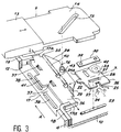
- the plate 21 On its front edge 21a looking at the movement transmission plate 17, the plate 21 carries a projecting tooth 22 centered on its axis X and slightly raised relative to the inner face of the wall 10 of the housing while being substantially parallel thereto.
- the secondary box 2 is further provided with a traditional double key locking cylinder 23 supported by the rear and front walls 10, 11 of the box 2, just below the plate 21.
- FIG. 4 it can be seen that the guide of the plate 21 is ensured by two tabs 27, 28, formed by a puncture, which engage, with minimal lateral play, in an oblong slot 29 of the rear wall 10 of the housing, with an axis parallel to the sliding direction X of the plate 21.
- FIG. 3 also shows that these guide tabs 27, 28 are arranged between the lower wing 26 of the plate 21 and the median longitudinal axis X of the latter.
- a leaf spring 30 fixed on a pillar 31, of short height, integral with the rear wall 10 of the housing. From this point of support, the spring leaf 30 extends forward, on an axis substantially parallel to the sliding axis X of the plate 21, to push the latter against the wall 10 of the housing, by its free end provided with a small internal boss 32, formed here by a stamping.
- the plate 21 has, in its upper rear corner, a cutout 33 located directly above the spring leaf 30, cutout through which the pillar 31 stands in the retracted position of the plate 21, shown in FIG. 4 and in phantom in Figure 2. From its support pillar 31, the leaf spring 30 has a length such that in this same retracted position of the plate 21, the boss end 32 comes to engage in front of the front edge 21a of the latter in order to immobilize it (FIG. 5).
- the movement transmission plate 17 comprises, on the side of the plate 21, a lateral wing 34, raised relative to the internal face of the rear wall 10 of the housing 2.
- This wing 34 on which stands the stud 16 and rests with sliding the tail 14 of the bolt 9, is connected, by a short veil 35 inclining slightly towards the plate 21, to a base part 36 provided with tabs 37 formed by punctures and engaging in sliding slots 38 of the wall 10 of the housing to guide the plate 17 in the direction A.
- An opening 39 is made in the elbow 40 joining the base part 36 of the plate 17 to the veil 35.
- This opening 39 which defines a notch opening facing the front edge 21a of the plate 21, is positioned so as to be on the axis X of the latter, in the active position of the plate 17.
- the notch thus defined has a width slightly greater than that of the front tooth 22 of the locking plate 21.
- the plate 17 is also applied against the headrest 4 by a heel 41.
- the blocking plate 21 When from its retracted position in FIG. 5, the blocking plate 21 is moved by the pivoting of the bit 24 towards the transmission plate 17 in the active position, its front edge 21a abuts against the inclined web 35 of the latter and its front tooth 22 engages closely in the notch 39, as shown in FIG. 4. In this way, the transmission plate is immobilized in its active position, consequently achieving a locking of the dead bolt 9 in the locking position.
- the immobilization of the plate 21 in its advanced locking position of FIG. 4 is ensured by the spring leaf, the boss 32 of which engages in a recess 42 in the free face of the plate 21.
- a pivoting movement in the direction reverse of the bit 24 will bring the plate 21 into its retracted position to release the plate 17.
- the bolt 9 can then be actuated normally from the cylinder 8 of the main housing 1 of the lock.
- the same locking mechanism will be provided in the housing lower secondary 3, the position of the notch of the transmission plate 17 being simply shifted upwards, along the elbow 40 of the latter, relative to that of the notch 39.
- the plate 17 will be provided with two notches thus offset 39.43 to be able to be indifferently mounted in the upper secondary housing or the lower secondary housing.
Landscapes
- Engineering & Computer Science (AREA)
- Mechanical Engineering (AREA)
- Structural Engineering (AREA)
- Lock And Its Accessories (AREA)
Claims (10)
- Mehrriegelschloß mit mehreren Schloßriegeln (7, 9), die in jeweiligen, an unterschiedlichen Stellen entlang einer Türkante anzubringenden Gehäusen (1, 2, 3) gehalten werden, wobei das eine Gehäuse ein Hauptgehäuse (1) bildet, das ein schlüsselbetätigbares Organ (8) für seinen Riegel (7) enthält, und das bzw. die anderen Gehäuse je ein Nebengehäuse (2, 3) bilden, wobei dessen Riegel (9), der durch eine Öffnung (12) in einem die vordere (10) und die hintere (11) Wand des Gehäuses verbindenden Schloßstulp (4) verschiebbar ist, mittels einer mit dem Riegel (7) des Hauptgehäuses (1) gekuppelten Treibstange (18, 18a) verstellbar ist und entweder in eine Verriegelungsstellung gebracht und festgehalten werden kann, in der er aus dem Schloßstulp (4) ausgefahren ist, oder in eine Entriegelungsstellung, in der er etwa bündig mit letzterem eingefahren ist,
dadurch gekennzeichnet, daß mindestens eines der Nebengehäuse (2) ein bewegliches Glied (21) zum Sperren seines Riegels (9) in Verriegelungsstellung umfaßt, das mittels eines schlüsselbetätigbaren, von der Treibstange unabhängigen Organs steuerbar ist. - Mehrriegelschloß nach Anspruch 1, dadurch gekennzeichnet, daß das Betätigungsorgan des beweglichen Gliedes (21) zum Sperren des Riegels (9) des Nebengehäuses (2) eine andere Codierung aufweist, als die des schlüsselbetätigbaren Organs (8) des Riegels (7) des Hauptgehäuses (1).
- Mehrriegelschloß nach Anspruch 1 oder 2, dadurch gekennzeichnet, daß das Nebengehäuse (2) ein Bewegungsübertragungs-Element (17) umfaßt, das in einer Richtung (A) etwa senkrecht zur Verschieberichtung des Riegels verschiebbar gelagert ist, mit dem das Element (17) durch Bewegungsumkehrmittel (15, 16) gekuppelt ist und dabei mit der Treibstange (18) verbunden ist, damit es von dieser entweder in eine aktive Stellung gebracht wird, in der es den Riegel (9) in die Verriegelungsstellung bringt, oder in eine Ruhestellung, in der es den Riegel (9) in die Entriegelungsstellung rückstellt, wobei das Sperrglied (21) in einer Richtung (X) quer zur Veschieberichtung (A) des Übertragungselementes zwischen einer eingefahrenen Stellung und einer ausgefahrenen Stellung verstellbar ist und eine in Richtung auf das Übertragungselement (17) stirnseitig vorspringende Nocke (22) aufweist, die in der ausgefahrenen Stellung des Sperrgliedes (21) in eine eine ergänzende Form aufweisende Rastkerbe (39) des Übertragungselementes eingreifen kann, die in der aktiven Stellung des Sperrgliedes diesem gegenüberliegt.
- Mehrriegelschloß nach Anspruch 3, dadurch gekennzeichnet, daß das Sperrglied (21) die Form eines Plättchens aufweist, das durch Führungsmittel entlang der einen (10) vorderen und hinteren Wand des Gehäuses (2) in seiner Bewegungsrichtung verschiebbar gehalten wird.
- Mehrriegelschloß nach Anspruch 4, dadurch gekennzeichnet, daß die Führungsmittel zum einen einen oder mehrere Vorsprünge (27, 28) umfaßen, die auf einen der gegenüberliegenden Seiten des Plättchens (21) bzw. der Wand (10) des Gehäuses ausgebildet sind, und die in eine Verschiebungsnut (29) auf der anderen Seite eingreifen, zum anderen ein Federblatt (30), das sich einerseits auf das Gehäuse (2) abstützt und sich andererseits an die gegenüberliegende freie Seite des Plättchens (21) anlegt.
- Mehrriegelschloß nach Anspruch 5, dadurch gekennzeichnet, daß das Federblatt (30) sich auf das Gehäuse (2) an der Rückseite des Plättchens (21) abstützt und am gegenüberliegenden freien Ende eine kleine Ausformung (32) aufweist, die in der eingefahrenen Stellung des Plättchens vor dessen Frontkante (21a) gelangt und in der ausgefahrenen Stellung des Plättchens in eine Vertiefung (42) auf dessen freier Seite einrastet.
- Mehrriegelschloß nach Anspruch 5 oder 6, dadurch gekennzeichnet, daß das Federblatt (30), das auf einer zur Verstellrichtung (X) des Plättchens etwa parallelen Achse gerichtet ist, sich auf die Wand (10) des Gehäuses (2), auf der das Plättchen gehalten ist, über eine Stütze (31) abstützt, die sich in der eingefahrenen Stellung des Plättchens innerhalb eines auf dessen hintere Kante gehenden Ausschnittes (33) befindet.
- Mehrriegelschloß nach einem der Ansprüche 5 bis 7, dadurch gekennzeichnet, daß da die Nocke (22) auf einer zur Verstellrichtung des Plättchens (21) etwa parallelen Achse (X) liegt und das Plättchen (21) über eine Seitenkante mit seinem Betätigungsglied zusammenarbeitet, die Vorsprünge (27, 28) und die zugehörige Verschiebungsnut (29) zwischen der Seitenkante des Plättchens und der Positionierachse (X) seiner Nocke (22) vorgesehen sind, während das Federblatt (30) auf dem Plättchen auf der anderen Seite der Achse angebracht ist.
- Mehrriegelschloß nach einem der Ansprüche 4 bis 8, dadurch gekennzeichnet, daß die auf der Frontkante des Plättchens (21) eingearbeite Nocke (22) höher liegt als die Innenseite der Wand (10) des Gehäuses (2), gegen der das Plättchen gehalten ist.
- Mehrriegelschloß nach einem der Ansprüche 3 bis 9, dadurch gekennzeichnet, daß das Übertragungselement (17) seinerseits als ein Plättchen ausgebildet ist, das auf der dem Sperrplättchen (21) zugewandten Seite einen hochliegenden Seitenflügel (34) aufweist, über den es mit dem Schloßriegel (9) gekuppelt wird, und der über einen Verbindungsstreifen (35) mit einem Grundteil (36) verbunden ist, durch welches das Übertragungsplättchen enlang der Gehäusewand verschoben wird, gegen der das Sperrplättchen (21) gehalten ist, wobei die Rastkerbe (39) des Übertragungsplättchens durch eine in letzterem eingearbeitete Öffnung gebildet wird, und zwar beiderseits der Achse, entlang der das Grundteil (36) sich über den Verbindungsstreifen (35) an den hochliegenden Seitenflügel (34) anschließt.
Applications Claiming Priority (2)
| Application Number | Priority Date | Filing Date | Title |
|---|---|---|---|
| FR9201824A FR2687428B1 (fr) | 1992-02-18 | 1992-02-18 | Serrure multi-points a pene secondaire condamnable independamment du pene principal. |
| FR9201824 | 1992-02-18 |
Publications (2)
| Publication Number | Publication Date |
|---|---|
| EP0557183A1 EP0557183A1 (de) | 1993-08-25 |
| EP0557183B1 true EP0557183B1 (de) | 1996-01-03 |
Family
ID=9426759
Family Applications (1)
| Application Number | Title | Priority Date | Filing Date |
|---|---|---|---|
| EP19930400387 Expired - Lifetime EP0557183B1 (de) | 1992-02-18 | 1993-02-17 | Mehrpunktschloss mit Sekundärriegeln, die unabhängig vom Hauptriegel verriegelbar sind |
Country Status (3)
| Country | Link |
|---|---|
| EP (1) | EP0557183B1 (de) |
| DE (1) | DE69301165D1 (de) |
| FR (1) | FR2687428B1 (de) |
Cited By (1)
| Publication number | Priority date | Publication date | Assignee | Title |
|---|---|---|---|---|
| SG101925A1 (en) * | 1998-11-13 | 2004-02-27 | Jamco Corp | Door latch device |
Families Citing this family (3)
| Publication number | Priority date | Publication date | Assignee | Title |
|---|---|---|---|---|
| DE9402161U1 (de) * | 1994-02-09 | 1995-06-08 | Gretsch-Unitas GmbH Baubeschläge, 71254 Ditzingen | Zusatzverriegelungsvorrichtung für ein Fenster, eine Tür o.dgl. mit einem wenigstens drehbarem Flügel |
| DE19607403A1 (de) * | 1996-02-28 | 1997-09-04 | Fliether Karl Gmbh & Co | Treibstangenverschluß |
| GB2310684A (en) * | 1996-02-29 | 1997-09-03 | Reynolds | Doors and door locks |
Family Cites Families (4)
| Publication number | Priority date | Publication date | Assignee | Title |
|---|---|---|---|---|
| DE263046C (de) * | ||||
| DE3505379C2 (de) * | 1985-02-16 | 1996-03-21 | Fliether Karl Gmbh & Co | Treibstangenschloß |
| US4892338A (en) * | 1988-10-13 | 1990-01-09 | The Eastern Company | Plural point door lock and flush-mountable operating mechanism with detent |
| FR2646458B1 (fr) * | 1989-04-28 | 1995-02-03 | Map Massard Sa | Dispositif de fermeture a verrouillage automatique par commande centralisee pour porte ou analogue |
-
1992
- 1992-02-18 FR FR9201824A patent/FR2687428B1/fr not_active Expired - Fee Related
-
1993
- 1993-02-17 EP EP19930400387 patent/EP0557183B1/de not_active Expired - Lifetime
- 1993-02-17 DE DE69301165T patent/DE69301165D1/de not_active Expired - Lifetime
Cited By (1)
| Publication number | Priority date | Publication date | Assignee | Title |
|---|---|---|---|---|
| SG101925A1 (en) * | 1998-11-13 | 2004-02-27 | Jamco Corp | Door latch device |
Also Published As
| Publication number | Publication date |
|---|---|
| FR2687428B1 (fr) | 1994-05-20 |
| DE69301165D1 (de) | 1996-02-15 |
| EP0557183A1 (de) | 1993-08-25 |
| FR2687428A1 (fr) | 1993-08-20 |
Similar Documents
| Publication | Publication Date | Title |
|---|---|---|
| EP0341173B1 (de) | Treibstangenverschluss für Türen, Fenster o.dgl. | |
| EP0952284B1 (de) | Verriegelungsvorrichtung für einen Schiebeflügel | |
| EP0172063B1 (de) | Schloss mit doppelter Verriegelung z.B. für Bankmietfächer | |
| FR2708025A1 (fr) | Dispositif de protection de barillet de serrure de porte. | |
| EP0557183A1 (de) | Mehrpunktschloss mit Sekundärriegeln, die unabhängig vom Hauptriegel verriegelbar sind | |
| EP3564467A1 (de) | Schliesssystem mit mechanischer verriegelung | |
| EP0928869B1 (de) | Verriegelungsbeschlag für Tür, Fenstertür oder dergleichen | |
| EP0651116B1 (de) | Türschloss mit Schutzeinrichtung | |
| FR2772810A3 (fr) | Poteau technique perfectionne pour porte anti-vandalisme | |
| EP0411969B1 (de) | Türschutzeinrichtung | |
| FR2652118A1 (fr) | Ensemble combine de sortie de secours et de serrure d'acces exterieur. | |
| EP0891465B1 (de) | Treibstange oder treibstangenschloss, insbesondere mit mehrpunktverriegelung | |
| EP0866204B1 (de) | Einbruchsichere Verriegelungsvorrichtung für einen Rolladenschrank | |
| FR2583452A1 (fr) | Boitier de cremone a plaquer avec condamnation. | |
| EP0633377B1 (de) | Sicherheitsschloss | |
| EP0495736A1 (de) | Einsteckschloss mit Schlossriegel | |
| FR2808553A1 (fr) | Systeme de verrouillage/deverrouillage pour porte fermiere | |
| FR2766859A1 (fr) | Serrure de loquet | |
| EP1149973B1 (de) | Verschlussvorrichtung für eine zweiflügelige Tür | |
| FR2722821A1 (fr) | Serrure de porte comportant au moins un dispositif de protection | |
| EP0147448A1 (de) | Sicherheitstüreinheit. | |
| FR2654142A1 (en) | Safety frame for closing rooms | |
| FR2851281A1 (fr) | Serrure a double commande simultanee | |
| FR2772809A3 (fr) | Poteau technique perfectionne pour porte anti-vandalisme | |
| EP4560098A1 (de) | Schlossanordnung |
Legal Events
| Date | Code | Title | Description |
|---|---|---|---|
| PUAI | Public reference made under article 153(3) epc to a published international application that has entered the european phase |
Free format text: ORIGINAL CODE: 0009012 |
|
| AK | Designated contracting states |
Kind code of ref document: A1 Designated state(s): BE DE ES GB IT LU NL PT |
|
| 17P | Request for examination filed |
Effective date: 19940121 |
|
| 17Q | First examination report despatched |
Effective date: 19950125 |
|
| GRAA | (expected) grant |
Free format text: ORIGINAL CODE: 0009210 |
|
| AK | Designated contracting states |
Kind code of ref document: B1 Designated state(s): BE DE ES GB IT LU NL PT |
|
| PG25 | Lapsed in a contracting state [announced via postgrant information from national office to epo] |
Ref country code: NL Free format text: LAPSE BECAUSE OF FAILURE TO SUBMIT A TRANSLATION OF THE DESCRIPTION OR TO PAY THE FEE WITHIN THE PRESCRIBED TIME-LIMIT Effective date: 19960103 Ref country code: IT Free format text: LAPSE BECAUSE OF FAILURE TO SUBMIT A TRANSLATION OF THE DESCRIPTION OR TO PAY THE FEE WITHIN THE PRE;WARNING: LAPSES OF ITALIAN PATENTS WITH EFFECTIVE DATE BEFORE 2007 MAY HAVE OCCURRED AT ANY TIME BEFORE 2007. THE CORRECT EFFECTIVE DATE MAY BE DIFFERENT FROM THE ONE RECORDED.SCRIBED TIME-LIMIT Effective date: 19960103 Ref country code: GB Effective date: 19960103 Ref country code: ES Free format text: THE PATENT HAS BEEN ANNULLED BY A DECISION OF A NATIONAL AUTHORITY Effective date: 19960103 |
|
| REF | Corresponds to: |
Ref document number: 69301165 Country of ref document: DE Date of ref document: 19960215 |
|
| PG25 | Lapsed in a contracting state [announced via postgrant information from national office to epo] |
Ref country code: BE Effective date: 19960228 |
|
| PG25 | Lapsed in a contracting state [announced via postgrant information from national office to epo] |
Ref country code: LU Free format text: LAPSE BECAUSE OF NON-PAYMENT OF DUE FEES Effective date: 19960229 |
|
| PG25 | Lapsed in a contracting state [announced via postgrant information from national office to epo] |
Ref country code: PT Effective date: 19960403 |
|
| PG25 | Lapsed in a contracting state [announced via postgrant information from national office to epo] |
Ref country code: DE Effective date: 19960404 |
|
| NLV1 | Nl: lapsed or annulled due to failure to fulfill the requirements of art. 29p and 29m of the patents act | ||
| GBV | Gb: ep patent (uk) treated as always having been void in accordance with gb section 77(7)/1977 [no translation filed] |
Effective date: 19960103 |
|
| BERE | Be: lapsed |
Owner name: S.A. BRICARD Effective date: 19960228 |
|
| PLBE | No opposition filed within time limit |
Free format text: ORIGINAL CODE: 0009261 |
|
| STAA | Information on the status of an ep patent application or granted ep patent |
Free format text: STATUS: NO OPPOSITION FILED WITHIN TIME LIMIT |
|
| 26N | No opposition filed |