EP0557193B1 - Gerät zum auf dem Zufall beruhenden Ziehen von flachen Figuren - Google Patents
Gerät zum auf dem Zufall beruhenden Ziehen von flachen Figuren Download PDFInfo
- Publication number
- EP0557193B1 EP0557193B1 EP93400405A EP93400405A EP0557193B1 EP 0557193 B1 EP0557193 B1 EP 0557193B1 EP 93400405 A EP93400405 A EP 93400405A EP 93400405 A EP93400405 A EP 93400405A EP 0557193 B1 EP0557193 B1 EP 0557193B1
- Authority
- EP
- European Patent Office
- Prior art keywords
- groove
- prism
- receptacle
- prisms
- fingers
- Prior art date
- Legal status (The legal status is an assumption and is not a legal conclusion. Google has not performed a legal analysis and makes no representation as to the accuracy of the status listed.)
- Expired - Lifetime
Links
Images


Classifications
-
- A—HUMAN NECESSITIES
- A63—SPORTS; GAMES; AMUSEMENTS
- A63F—CARD, BOARD, OR ROULETTE GAMES; INDOOR GAMES USING SMALL MOVING PLAYING BODIES; VIDEO GAMES; GAMES NOT OTHERWISE PROVIDED FOR
- A63F7/00—Indoor games using small moving playing bodies, e.g. balls, discs or blocks
- A63F7/04—Indoor games using small moving playing bodies, e.g. balls, discs or blocks using balls to be shaken or rolled in small boxes, e.g. comprising labyrinths
- A63F7/048—Indoor games using small moving playing bodies, e.g. balls, discs or blocks using balls to be shaken or rolled in small boxes, e.g. comprising labyrinths used for generating random numbers
-
- G—PHYSICS
- G07—CHECKING-DEVICES
- G07C—TIME OR ATTENDANCE REGISTERS; REGISTERING OR INDICATING THE WORKING OF MACHINES; GENERATING RANDOM NUMBERS; VOTING OR LOTTERY APPARATUS; ARRANGEMENTS, SYSTEMS OR APPARATUS FOR CHECKING NOT PROVIDED FOR ELSEWHERE
- G07C15/00—Generating random numbers; Lottery apparatus
- G07C15/001—Generating random numbers; Lottery apparatus with balls or the like
-
- A—HUMAN NECESSITIES
- A63—SPORTS; GAMES; AMUSEMENTS
- A63F—CARD, BOARD, OR ROULETTE GAMES; INDOOR GAMES USING SMALL MOVING PLAYING BODIES; VIDEO GAMES; GAMES NOT OTHERWISE PROVIDED FOR
- A63F7/00—Indoor games using small moving playing bodies, e.g. balls, discs or blocks
- A63F7/22—Accessories; Details
- A63F7/34—Other devices for handling the playing bodies, e.g. bonus ball return means
- A63F2007/348—Anti-blocking devices for balls
-
- A—HUMAN NECESSITIES
- A63—SPORTS; GAMES; AMUSEMENTS
- A63F—CARD, BOARD, OR ROULETTE GAMES; INDOOR GAMES USING SMALL MOVING PLAYING BODIES; VIDEO GAMES; GAMES NOT OTHERWISE PROVIDED FOR
- A63F9/00—Games not otherwise provided for
- A63F9/0079—Games using compressed air, e.g. with air blowers, balloons, vacuum
- A63F2009/0087—Games using compressed air, e.g. with air blowers, balloons, vacuum with means for producing an air current
-
- A—HUMAN NECESSITIES
- A63—SPORTS; GAMES; AMUSEMENTS
- A63F—CARD, BOARD, OR ROULETTE GAMES; INDOOR GAMES USING SMALL MOVING PLAYING BODIES; VIDEO GAMES; GAMES NOT OTHERWISE PROVIDED FOR
- A63F9/00—Games not otherwise provided for
- A63F9/24—Games using electronic circuits not otherwise provided for
- A63F2009/2401—Detail of input, input devices
- A63F2009/2436—Characteristics of the input
- A63F2009/2442—Sensors or detectors
- A63F2009/2444—Light detector
- A63F2009/2445—Light detector detecting reflected light
Definitions
- the present invention relates to a device for the random drawing of plane figures such as those represented on playing cards for example.
- Machines are known for performing the random drawing of balls. Such a machine is described in the European patent application published under No. 0 348 281.
- This machine has a spherical receptacle in which the balls are kept in motion by a judiciously oriented air flow.
- the machine also comprises a tube capable of passing through the spherical receptacle and in which a depression can be created so as to suck up the ball, which passes near the upper orifice of said tube, and to maintain it on said end.
- a machine of this type does not allow agitation of flat objects such as playing cards, the air current having the effect of pressing said objects against the wall of the receptacle.
- the air is sent into the sphere so as to create an air current which produces a movement extending from the back to the front.
- the prisms are introduced into the sphere and agitated by the air flow, it can be seen that all the prisms move along a circular trajectory which, on average, is contained substantially in the vertical plane of symmetry of the above-mentioned groove.
- each prism has a figurine on each of its faces.
- each figure in the deck of cards is reproduced on the front and back of a flattened prism, such as that shown in 1 in FIGS. 1 and 2.
- a flattened prism such as that shown in 1 in FIGS. 1 and 2.
- the thickness of each prism is of the order of a few millimeters. Except for the prints, all the prisms are strictly identical in size and density.
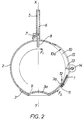
- the prisms 1 are introduced into a spherical receptacle 2, the lower part of which, which is open, rests on a base 3 made integral with a frame shown diagrammatically at 4 in FIG. 1.
- Means are provided for fixing the receptacle 2 on the base 3.
- a rapid assembly means of a known type such as that known as with bayonet according to which the assembly is carried out by an axial displacement of the sphere followed by a rotation along this axis. .
- the sphere 2 can be surmounted by a charger 5 constituted by a plurality of vertical grooves 6 in which the prisms 1 are engaged and are visible.
- the grooves 6 communicate, via a retractable hatch 7, with the receptacle 2 which has, for this purpose, a slot 8.
- the base 3 has an opening 9 through which air is circulated in the sphere 2 in a direction which is substantially that of the curvilinear arrow F flèche. Under the effect of this air flow all the prisms are driven, substantially, in the same direction.
- the air jet can be controlled by pivoting shutters, similar to those described in the aforementioned European patent application, the axes of which appear in dashed lines in FIG. 4.
- the central portion 3a of the base 3 is curved so as to partially penetrate the shere 2 and the opening 9 is located at the periphery of said portion and rearwardly. In this way, the prisms are deflected and do not risk hitting the rear edge of the opening, which could damage them.
- the front part of the sphere has a groove 10, the bottom 10 a of which is offset towards the outside.
- the groove 10 has a trapezoidal section and its width decreases from its upper part to that lower.
- the bottom 10 a partially covers the portion 2 a of the sphere 2 while providing sufficient space to allow the passage of a prism.
- the lower end of the groove 10 is normally closed by a movable bar 11 so as to form a groove 12 into which the lower part of the prism penetrates.
- prisms can penetrate the groove 10, slide along the bottom 10 a and that one of them can be inserted in the space between the portion 2 a and the bottom of the groove bearing against the bar 11 (position shown in FIG. 2).
- the width of the groove 10, at its lower part, is such that only the prisms which are in the correct position, that shown in Figure 1, can be captured, the others being deflected through the oblique blanks of said groove and returned to the center of the sphere. From the aforementioned position, it suffices to retract the bar 11 to evacuate the prism using an appropriate chute, not shown. The draw is over.
- means are provided for delaying the capture of a prism and for protecting the captured prism.
- a first means which detects the presence of a prism in the groove 12 and a second means, placed under the dependence of the first, for isolating the captured prism.
- Different means can be used to detect the presence of a prism.
- a fiber optic device housed in the bar 11 is used.
- a first optical fiber sends a light ray, a part of which is reflected towards the end of a second optical fiber when a prism enters the groove 12, creating thus a signal which is used to control the installation of protective device.
- the entire operation is almost instantaneous and takes place in a time which is less than or one thousandth of a second.
- the protective member is constituted by fingers 13 capable of extending in the groove 10. These fingers are carried by a shaft 14 disposed outside the groove, the bottom of which has openings 15 for the passage of said fingers.
- a single light 15 is shown in FIG. 1. With regard to the lights 15, it should be pointed out that these are determined so as to provide a section suitable for the air which must come out of the sphere 2.
- the fingers 13 are used to delay the drawing and, for this purpose, they extend naturally in the groove 10 according to the position shown in FIG. 2.
- the fingers 13 are retracted and no longer project from the bottom of the groove 12.
- the pivoting of the shaft 14 is controlled to place the fingers 13 in the position shown in FIG. 2. In this position, the end of the fingers is tangent to the extension of the internal surface of the sphere. The prisms which are in motion strike the fingers and are returned towards the center of the sphere without being able to reach the captured prism.
- the rotation of the shaft 14 can be controlled by moving the movable armature of an electromagnet of the plunger core type, the rod of which can act on a lateral extension 16 of the shaft 14.
- the control of the retraction of the bar 11 can be achieved by moving it parallel to itself in the direction of the arrow F2. This move poses no technical problem.
- the bar 11 when it is desired to delay the drawing, the bar 11 is moved parallel to itself and upwards so as to place it in a position where the groove is completely closed. In this position it is therefore not possible to capture a prism.
- the movement, in the opposite direction, of the bar is controlled so as to recreate the groove 12 and allow the capture of a prism.
- the resulting signal is used to control the stopping of the blower producing the current of air inside the sphere.
- the prisms no longer receiving energy all fall to the bottom of the sphere with the exception of the captured one which can no longer be struck by the others.
Landscapes
- Engineering & Computer Science (AREA)
- Multimedia (AREA)
- Physics & Mathematics (AREA)
- General Physics & Mathematics (AREA)
- Toys (AREA)
- Liquid Crystal (AREA)
- Bidet-Like Cleaning Device And Other Flush Toilet Accessories (AREA)
- Wire Bonding (AREA)
- Feeding Of Articles To Conveyors (AREA)
- Road Signs Or Road Markings (AREA)
- Mechanical Pencils And Projecting And Retracting Systems Therefor, And Multi-System Writing Instruments (AREA)
Claims (8)
- Vorrichtung zum beliebigen Ziehen von flachen Figuren, bestehend aus- einer Maschine, die im Wesentlichen von einem sphärischen Behälter (2) gebildet wird, in dem ein Luftstrom erzeugt werden kann,
dadurch gekennzeichnet, daß sie zusätzlich auch- abgeflachte Prismen (1) aufweist, wobei die Prismen (1) eine der flachen Figuren auf einer ihrer sich gegenüber befindlichen Seiten abbilden und in den Behälter (2) eingeführt werden, der sphärische Behälter Mittel zum beliebigen Festhalten eines dieser Prismen besitzt und auf dem nach vorn gerichteten Teil eine Rille (10) mit trapezförmigem Querschnitt aufweist, deren Breite von oben nach unten abnimmt und deren Bodenfläche (10a) sich im unteren Teil über die Außenseite des Behälters erstreckt, wodurch ein ausreichend großer Raum zum Hindurchführen eines Prismas (1) gebildet wird. - Vorrichtung nach Patentanspruch 1, dadurch gekennzeichnet, daß der im obigen Patentanspruch definierte Raum mit einer ausziehbaren Leiste (11) versperrt wird, welche den Boden einer Rille bildet, in die das Unterteil eines Prismas eingeführt werden kann.
- Vorrichtung nach Patentanspruch 2, dadurch gekennzeichnet, daß Mittel zum Verzögern des Ziehens, Verbergen eines in der Rille (12) vorhandenen Prismas und Anbringen eines Mittels zum Schützen des eingefangenen Prismas vorhanden sind.
- Vorrichtung nach Patentanspruch 3, dadurch gekennzeichnet, daß als Mittel zum Schützen des Prismas eine Vorrichtung mit einer Vielzahl von Fingern (13) verwendet wird, die in die Rille (10) eingeführt werden, sobald ein Prisma eingefangen wird, um zu verhindern, daß es mit den übrigen in dem sphärischen Behälter in Bewegung befindlichen Prismen zusammenstößt.
- Vorrichtung nach Patentanspruch 4, dadurch gekennzeichnet, daß die Finger (13) an einer Welle (14) befestigt sind, die außerhalb des Behälters angebracht ist, wobei bei einer Drehung der Welle die Finger in die Rille (10) eingeführt werden und deren Boden aufgrund von darin vorgesehenen Öffnungen (15) durchqueren können.
- Vorrichtung nach Patentanspruch 1 bis 5, dadurch gekennzeichnet, daß der sphärische Behälter auf seiner Unterseite geöffnet ist und auf einem Sockel aufliegt, der fest mit dem Gestell der Maschine verbunden ist, dessen zentraler Teil gewölbt ist und teilweise ins Innere des Behälters hineinragt, wobei der zentrale Teil an seinem Rand und nach hinten gerichtet eine Luftaustrittsöffnung (9) aufweist.
- Vorrichtung nach Patentanspruch 3, dadurch gekennzeichnet, daß die Leiste (11) parallel zu sich selbst verlagert werden kann, um die Rille (12) zu versperren.
- Vorrichtung nach Patentanspruch 7, dadurch gekennzeichnet, daß das beim Erkennen eines Prismas in der Rille (12) erzeugte Signal zum Abschalten des Gebläses zum Erzeugen des Luftstromes verwendet wird.
Applications Claiming Priority (2)
| Application Number | Priority Date | Filing Date | Title |
|---|---|---|---|
| FR9201917 | 1992-02-20 | ||
| FR9201917A FR2687581B1 (fr) | 1992-02-20 | 1992-02-20 | Dispositif pour le tirage aleatoire de figures planes. |
Publications (2)
| Publication Number | Publication Date |
|---|---|
| EP0557193A1 EP0557193A1 (de) | 1993-08-25 |
| EP0557193B1 true EP0557193B1 (de) | 1996-04-24 |
Family
ID=9426825
Family Applications (1)
| Application Number | Title | Priority Date | Filing Date |
|---|---|---|---|
| EP93400405A Expired - Lifetime EP0557193B1 (de) | 1992-02-20 | 1993-02-18 | Gerät zum auf dem Zufall beruhenden Ziehen von flachen Figuren |
Country Status (6)
| Country | Link |
|---|---|
| US (1) | US5312103A (de) |
| EP (1) | EP0557193B1 (de) |
| AT (1) | ATE137128T1 (de) |
| DE (1) | DE69302300T2 (de) |
| ES (1) | ES2088240T3 (de) |
| FR (1) | FR2687581B1 (de) |
Families Citing this family (8)
| Publication number | Priority date | Publication date | Assignee | Title |
|---|---|---|---|---|
| FR2731539B1 (fr) * | 1995-03-07 | 1997-04-30 | Chateau Clotaire Raoul Georges | Machine pour le tirage aleatoire de boules |
| FR2762117B1 (fr) * | 1997-04-11 | 1999-07-16 | Clotaire Raoul Georges Chateau | Machine de tirage, notamment pour jeu de loto |
| WO2000003360A1 (fr) | 1998-07-10 | 2000-01-20 | Clotaire Raoul Georges Chateau | Machine de tirage, notamment, pour jeu de loto |
| US6435501B2 (en) * | 2000-04-14 | 2002-08-20 | Mark Cameron Naden | Random number generator |
| US7311304B1 (en) * | 2001-07-13 | 2007-12-25 | Arcade Planet, Inc. | Game apparatus with multiple moving elements |
| US20040007812A1 (en) * | 2002-07-12 | 2004-01-15 | Victor Terechko | Pocket random number selector |
| US20050098944A1 (en) * | 2003-11-07 | 2005-05-12 | Steven Brandstetter | Bingo ball games |
| CN104415551B (zh) * | 2013-09-10 | 2018-12-04 | 美泰有限公司 | 拼块分配器和分配拼块的方法 |
Family Cites Families (14)
| Publication number | Priority date | Publication date | Assignee | Title |
|---|---|---|---|---|
| US2696385A (en) * | 1951-03-15 | 1954-12-07 | John W Hadfield | Card shuffler |
| US2657059A (en) * | 1951-09-14 | 1953-10-27 | Selig Pearl | Magnetic lot selecting device |
| US2731268A (en) * | 1954-03-26 | 1956-01-17 | Charles S Raizen | Token-mixing device for games |
| US2792227A (en) * | 1954-09-20 | 1957-05-14 | Auerbach Mary | Chance controlled game device |
| US2889961A (en) * | 1957-02-07 | 1959-06-09 | Michael J Belmonte | Dispensing device |
| FR1225047A (fr) * | 1959-02-12 | 1960-06-28 | Jeu | |
| CH389478A (de) * | 1960-04-02 | 1965-03-15 | Leonhart Xaver | Vorrichtung zur Verhinderung des Zustopfens von Balleinläufen bei Tischfussballspielen |
| SE432886B (sv) * | 1982-06-21 | 1984-04-30 | Int Marketing Consultants Ets | Anordning for blandning och hasardartad avskiljning i identifierbar ordning av ett antal i en behallare befintliga element, foretredesvis merkta bollelement |
| US4732387A (en) * | 1987-09-16 | 1988-03-22 | Elinski Joseph C | Dispensing container |
| US4786056A (en) * | 1987-10-30 | 1988-11-22 | Dunnigan Richard P | Random number generator |
| US4813676A (en) * | 1987-12-07 | 1989-03-21 | Wallace Weatherspoon | Lottery number selection device |
| FR2646730B2 (fr) * | 1988-06-24 | 1993-02-19 | Chateau Clotaire | Machine pour le tirage aleatoire de boules |
| US5050880A (en) * | 1990-08-17 | 1991-09-24 | Randy Sloan | Random distribution machine |
| US5125659A (en) * | 1991-06-07 | 1992-06-30 | Leon Garbee | Rotatable drum for selecting lottery numbers |
-
1992
- 1992-02-20 FR FR9201917A patent/FR2687581B1/fr not_active Expired - Fee Related
-
1993
- 1993-02-18 ES ES93400405T patent/ES2088240T3/es not_active Expired - Lifetime
- 1993-02-18 US US08/019,433 patent/US5312103A/en not_active Expired - Fee Related
- 1993-02-18 EP EP93400405A patent/EP0557193B1/de not_active Expired - Lifetime
- 1993-02-18 AT AT93400405T patent/ATE137128T1/de not_active IP Right Cessation
- 1993-02-18 DE DE69302300T patent/DE69302300T2/de not_active Expired - Fee Related
Also Published As
| Publication number | Publication date |
|---|---|
| EP0557193A1 (de) | 1993-08-25 |
| ES2088240T3 (es) | 1996-08-01 |
| FR2687581B1 (fr) | 1996-10-25 |
| DE69302300D1 (de) | 1996-05-30 |
| FR2687581A1 (fr) | 1993-08-27 |
| US5312103A (en) | 1994-05-17 |
| DE69302300T2 (de) | 1996-12-12 |
| ATE137128T1 (de) | 1996-05-15 |
Similar Documents
| Publication | Publication Date | Title |
|---|---|---|
| EP0587883B1 (de) | Vorrichtung zur trennung von münzen, automatenmünzen oder dergleichen und selbsttätige bezahlapparate | |
| EP0672601B1 (de) | Vorrichtung zum Zuführen von Bögen oder Umschlägen welche bedruckt werden müssen | |
| FR2635983A1 (en) | Spinning-top battle game | |
| EP0348281A1 (de) | Maschine zum auf den Zufall beruhenden Ziehen von Kugeln | |
| EP0557193A1 (de) | Gerät zum auf dem Zufall beruhenden Ziehen von flachen Figuren | |
| FR3045550A1 (fr) | Dispositif deflecteur aerodynamique pour roue de vehicule automobile | |
| EP0320328B1 (de) | Aufzeichnungsapparat mit winkelförmigem Blattträger | |
| FR2593035A1 (fr) | Systeme aerodynamique et antibuee de coque et d'ecran de vision d'un casque de protection. | |
| EP0136951A2 (de) | Mehrzweckvorrichtung für die Projektion sowie Retroprojektion von Diapositiven | |
| EP0012881A2 (de) | Vorrichtung zur automatischen Randbegrenzung an einer Schreibmaschine in Abhängigkeit von der Papierbreite | |
| FR2655753A1 (fr) | Machine a affranchir a tete d'affranchissement amovible. | |
| FR2633754A1 (fr) | Appareil de lecture/ecriture de cartes a circuits integres comprenant un verrouillage en position de la carte | |
| EP0297011A1 (de) | Mähconditioner | |
| EP0749088A1 (de) | Chipkartenabtaster | |
| EP1504905B1 (de) | Vorrichtung zur sofortigen Tintenstrahldüsenreinigung | |
| FR2657298A1 (fr) | Dispositif pour assurer le maintien d'un support d'impression sur un plateau de guidage dans la zone d'ecriture d'une machine a dessiner. | |
| EP0273898A2 (de) | Vorrichtung zum Entstapeln von Bögen | |
| EP1488726A1 (de) | Staubsaugerdüse | |
| FR2696572A1 (fr) | Elément d'affichage à dent sur les arêtes des faces verticales; panneau d'affichage et système d'affichage les comprenant. | |
| EP0643856A1 (de) | Kartenaufnahme mit auswurf zerissener karten und mit dieser kartenaufnahme ausgestatteter kartenleser. | |
| EP0249669A1 (de) | Spritzgegossene, eine Folie als Aussenschicht aufweisende Behälter sowie Verfahren, Vorrichtung und Form zu deren Herstellung | |
| FR2719143A1 (fr) | Contrôleur de pièces métalliques, notamment de pièces de monnaie. | |
| FR2949374A1 (fr) | Scie circulaire avec recuperation de sciure perfectionnee | |
| EP0371842B1 (de) | Vorrichtung zur Rückführung von festen Entwicklungsteilchen, die von einem Transportgasstrom getrennt worden sind, in einen offenen Behälter | |
| EP0281716A1 (de) | Maschine zur Pfandrückgabe für von Supermärkten zurückgenommene leere Flaschen |
Legal Events
| Date | Code | Title | Description |
|---|---|---|---|
| PUAI | Public reference made under article 153(3) epc to a published international application that has entered the european phase |
Free format text: ORIGINAL CODE: 0009012 |
|
| AK | Designated contracting states |
Kind code of ref document: A1 Designated state(s): AT BE CH DE DK ES FR GB GR IE IT LI LU MC NL PT SE |
|
| 17P | Request for examination filed |
Effective date: 19931221 |
|
| 17Q | First examination report despatched |
Effective date: 19940829 |
|
| 111L | Licence recorded |
Free format text: 0100 INTERNATIONALE DES JEUX |
|
| GRAA | (expected) grant |
Free format text: ORIGINAL CODE: 0009210 |
|
| AK | Designated contracting states |
Kind code of ref document: B1 Designated state(s): AT BE CH DE DK ES FR GB GR IE IT LI LU MC NL PT SE |
|
| PG25 | Lapsed in a contracting state [announced via postgrant information from national office to epo] |
Ref country code: NL Free format text: LAPSE BECAUSE OF FAILURE TO SUBMIT A TRANSLATION OF THE DESCRIPTION OR TO PAY THE FEE WITHIN THE PRESCRIBED TIME-LIMIT Effective date: 19960424 Ref country code: GR Free format text: LAPSE BECAUSE OF FAILURE TO SUBMIT A TRANSLATION OF THE DESCRIPTION OR TO PAY THE FEE WITHIN THE PRESCRIBED TIME-LIMIT Effective date: 19960424 Ref country code: DK Effective date: 19960424 Ref country code: AT Effective date: 19960424 |
|
| REF | Corresponds to: |
Ref document number: 137128 Country of ref document: AT Date of ref document: 19960515 Kind code of ref document: T |
|
| REG | Reference to a national code |
Ref country code: IE Ref legal event code: FG4D Free format text: 68105 |
|
| REF | Corresponds to: |
Ref document number: 69302300 Country of ref document: DE Date of ref document: 19960530 |
|
| REG | Reference to a national code |
Ref country code: ES Ref legal event code: BA2A Ref document number: 2088240 Country of ref document: ES Kind code of ref document: T3 |
|
| ITF | It: translation for a ep patent filed | ||
| PG25 | Lapsed in a contracting state [announced via postgrant information from national office to epo] |
Ref country code: SE Effective date: 19960724 Ref country code: PT Effective date: 19960724 |
|
| GBT | Gb: translation of ep patent filed (gb section 77(6)(a)/1977) |
Effective date: 19960705 |
|
| REG | Reference to a national code |
Ref country code: ES Ref legal event code: FG2A Ref document number: 2088240 Country of ref document: ES Kind code of ref document: T3 |
|
| NLV1 | Nl: lapsed or annulled due to failure to fulfill the requirements of art. 29p and 29m of the patents act | ||
| PG25 | Lapsed in a contracting state [announced via postgrant information from national office to epo] |
Ref country code: IE Free format text: LAPSE BECAUSE OF NON-PAYMENT OF DUE FEES Effective date: 19961107 |
|
| REG | Reference to a national code |
Ref country code: IE Ref legal event code: FD4D Ref document number: 68105 Country of ref document: IE |
|
| PG25 | Lapsed in a contracting state [announced via postgrant information from national office to epo] |
Ref country code: LU Free format text: LAPSE BECAUSE OF NON-PAYMENT OF DUE FEES Effective date: 19970228 Ref country code: BE Effective date: 19970228 |
|
| PLBE | No opposition filed within time limit |
Free format text: ORIGINAL CODE: 0009261 |
|
| STAA | Information on the status of an ep patent application or granted ep patent |
Free format text: STATUS: NO OPPOSITION FILED WITHIN TIME LIMIT |
|
| 26N | No opposition filed | ||
| BERE | Be: lapsed |
Owner name: CHATEAU CLOTAIRE RAOUL GEORGES Effective date: 19970228 |
|
| PG25 | Lapsed in a contracting state [announced via postgrant information from national office to epo] |
Ref country code: MC Effective date: 19970831 |
|
| REG | Reference to a national code |
Ref country code: FR Ref legal event code: TP Ref country code: FR Ref legal event code: RL Ref country code: FR Ref legal event code: CL |
|
| REG | Reference to a national code |
Ref country code: FR Ref legal event code: CL |
|
| REG | Reference to a national code |
Ref country code: GB Ref legal event code: IF02 |
|
| REG | Reference to a national code |
Ref country code: FR Ref legal event code: TP Ref country code: FR Ref legal event code: CD |
|
| PGFP | Annual fee paid to national office [announced via postgrant information from national office to epo] |
Ref country code: ES Payment date: 20040218 Year of fee payment: 12 |
|
| PGFP | Annual fee paid to national office [announced via postgrant information from national office to epo] |
Ref country code: FR Payment date: 20040224 Year of fee payment: 12 |
|
| PGFP | Annual fee paid to national office [announced via postgrant information from national office to epo] |
Ref country code: GB Payment date: 20040225 Year of fee payment: 12 |
|
| PGFP | Annual fee paid to national office [announced via postgrant information from national office to epo] |
Ref country code: CH Payment date: 20040226 Year of fee payment: 12 |
|
| PGFP | Annual fee paid to national office [announced via postgrant information from national office to epo] |
Ref country code: DE Payment date: 20040428 Year of fee payment: 12 |
|
| PG25 | Lapsed in a contracting state [announced via postgrant information from national office to epo] |
Ref country code: IT Free format text: LAPSE BECAUSE OF NON-PAYMENT OF DUE FEES;WARNING: LAPSES OF ITALIAN PATENTS WITH EFFECTIVE DATE BEFORE 2007 MAY HAVE OCCURRED AT ANY TIME BEFORE 2007. THE CORRECT EFFECTIVE DATE MAY BE DIFFERENT FROM THE ONE RECORDED. Effective date: 20050218 Ref country code: GB Free format text: LAPSE BECAUSE OF NON-PAYMENT OF DUE FEES Effective date: 20050218 |
|
| PG25 | Lapsed in a contracting state [announced via postgrant information from national office to epo] |
Ref country code: ES Free format text: LAPSE BECAUSE OF NON-PAYMENT OF DUE FEES Effective date: 20050219 |
|
| PG25 | Lapsed in a contracting state [announced via postgrant information from national office to epo] |
Ref country code: LI Free format text: LAPSE BECAUSE OF NON-PAYMENT OF DUE FEES Effective date: 20050228 Ref country code: CH Free format text: LAPSE BECAUSE OF NON-PAYMENT OF DUE FEES Effective date: 20050228 |
|
| PG25 | Lapsed in a contracting state [announced via postgrant information from national office to epo] |
Ref country code: DE Free format text: LAPSE BECAUSE OF NON-PAYMENT OF DUE FEES Effective date: 20050901 |
|
| GBPC | Gb: european patent ceased through non-payment of renewal fee |
Effective date: 20050218 |
|
| PG25 | Lapsed in a contracting state [announced via postgrant information from national office to epo] |
Ref country code: FR Free format text: LAPSE BECAUSE OF NON-PAYMENT OF DUE FEES Effective date: 20051031 |
|
| REG | Reference to a national code |
Ref country code: FR Ref legal event code: ST Effective date: 20051031 |
|
| REG | Reference to a national code |
Ref country code: ES Ref legal event code: FD2A Effective date: 20050219 |
|
| REG | Reference to a national code |
Ref country code: CH Ref legal event code: PL Ref country code: CH Ref legal event code: NV Representative=s name: BOVARD AG PATENTANWAELTE Ref country code: CH Ref legal event code: EP |