EP0557549A1 - Transformateur à noyau annulaire - Google Patents
Transformateur à noyau annulaire Download PDFInfo
- Publication number
- EP0557549A1 EP0557549A1 EP92103238A EP92103238A EP0557549A1 EP 0557549 A1 EP0557549 A1 EP 0557549A1 EP 92103238 A EP92103238 A EP 92103238A EP 92103238 A EP92103238 A EP 92103238A EP 0557549 A1 EP0557549 A1 EP 0557549A1
- Authority
- EP
- European Patent Office
- Prior art keywords
- winding
- toroidal
- core
- transformer according
- wound
- Prior art date
- Legal status (The legal status is an assumption and is not a legal conclusion. Google has not performed a legal analysis and makes no representation as to the accuracy of the status listed.)
- Granted
Links
- 238000004804 winding Methods 0.000 claims description 47
- 238000005266 casting Methods 0.000 claims description 15
- 239000011347 resin Substances 0.000 claims description 15
- 229920005989 resin Polymers 0.000 claims description 15
- 238000009413 insulation Methods 0.000 claims description 8
- 238000005520 cutting process Methods 0.000 claims description 7
- 238000000034 method Methods 0.000 claims description 6
- 229910001021 Ferroalloy Inorganic materials 0.000 claims description 3
- 229920001296 polysiloxane Polymers 0.000 claims description 3
- 239000011248 coating agent Substances 0.000 claims description 2
- 238000000576 coating method Methods 0.000 claims description 2
- 239000000463 material Substances 0.000 claims description 2
- 238000009423 ventilation Methods 0.000 claims description 2
- 230000001154 acute effect Effects 0.000 claims 1
- 238000004382 potting Methods 0.000 claims 1
- 238000004519 manufacturing process Methods 0.000 abstract description 5
- XEEYBQQBJWHFJM-UHFFFAOYSA-N Iron Chemical compound [Fe] XEEYBQQBJWHFJM-UHFFFAOYSA-N 0.000 description 4
- 239000002184 metal Substances 0.000 description 4
- 229910052751 metal Inorganic materials 0.000 description 4
- 239000011810 insulating material Substances 0.000 description 3
- PXHVJJICTQNCMI-UHFFFAOYSA-N Nickel Chemical compound [Ni] PXHVJJICTQNCMI-UHFFFAOYSA-N 0.000 description 2
- 229910000640 Fe alloy Inorganic materials 0.000 description 1
- 229910000676 Si alloy Inorganic materials 0.000 description 1
- 230000006978 adaptation Effects 0.000 description 1
- 238000004873 anchoring Methods 0.000 description 1
- 230000015556 catabolic process Effects 0.000 description 1
- 230000005684 electric field Effects 0.000 description 1
- 238000010292 electrical insulation Methods 0.000 description 1
- 238000005538 encapsulation Methods 0.000 description 1
- 230000017525 heat dissipation Effects 0.000 description 1
- 238000009434 installation Methods 0.000 description 1
- 239000012774 insulation material Substances 0.000 description 1
- 229910052742 iron Inorganic materials 0.000 description 1
- 229910052759 nickel Inorganic materials 0.000 description 1
- 238000003466 welding Methods 0.000 description 1
Images


Classifications
-
- H—ELECTRICITY
- H01—ELECTRIC ELEMENTS
- H01F—MAGNETS; INDUCTANCES; TRANSFORMERS; SELECTION OF MATERIALS FOR THEIR MAGNETIC PROPERTIES
- H01F41/00—Apparatus or processes specially adapted for manufacturing or assembling magnets, inductances or transformers; Apparatus or processes specially adapted for manufacturing materials characterised by their magnetic properties
- H01F41/005—Impregnating or encapsulating
-
- H—ELECTRICITY
- H01—ELECTRIC ELEMENTS
- H01F—MAGNETS; INDUCTANCES; TRANSFORMERS; SELECTION OF MATERIALS FOR THEIR MAGNETIC PROPERTIES
- H01F30/00—Fixed transformers not covered by group H01F19/00
- H01F30/06—Fixed transformers not covered by group H01F19/00 characterised by the structure
- H01F30/16—Toroidal transformers
Definitions
- the invention relates to a method for producing a cast power resin cast with a wound cutting tape core, preferably made of a cold-rolled ferro alloy, which has a magnetic preferential direction, and a toroidal transformer produced by this method.
- Modern ferro alloys for the production of transformer sheets consisting essentially of iron / nickel or iron / silicon alloys, have very good magnetic properties which make it possible to construct transformers with correspondingly good electrical values, but are very difficult to process. Shall the good magnetic Properties of these transformer sheets are exploited, the magnetic preferred direction with the main flow direction in the transformer sheet must match as much as possible. This means that, for example, normal M-cuts cannot be used, but that with a three-column transformer, the preferred magnetic direction in the yokes must be perpendicular to that in the cores. In addition, the core and yoke sheets must be mitred to largely keep the flow direction in the preferred direction of the sheets.
- Toroidal transformers have been known for a long time, in which the transformer sheet, which is in tape form, is wound in a ring and then this toroid is wound with transformer coils. With such a toroidal transformer, the difficulties described above do not arise, since the direction of flow in the transformer sheet always corresponds to its preferred magnetic direction. Difficulties arise with such toroidal transformers due to the application of the windings special special winding machines. Toroidal transformers and chokes have therefore so far only been built for small outputs. Grid power transformers with this structure have not yet been disclosed.
- cutting band cores are also used which, like the toroidal core transformers, have a wound core, but usually wound in an approximate rectangular shape, which is cut at two points transversely to the longitudinal direction of the metal sheets. This makes it possible to place previously manufactured spools on the straight parts of these cut ribbon cores wound in a rectangular shape and then to bring the two core halves together again with the smallest possible air gap. This eliminates the difficulty of winding such cores, which also have extremely good electrical properties.
- only low-power transformers equipped with such cutting tape cores have so far become known.
- the toroidal transformer according to the invention thus differs from the known toroidal transformers with a ribbon core in that it does not have a rectangular wound core like this, but this winding core is circular.
- This has the disadvantage, ostensibly, that no cylindrical coils can be pushed onto the winding core, but that, and that probably prevented the experts from using such round winding cores, the winding and sliding on of the coils could be difficult. In fact this is not the case, if so, as by the Invention is set forth, since the low-voltage coil with its relatively thick wire cross-section pre-wound as an air coil and then can be pushed over the half-arch of the cut core without difficulty.
- the winding disks should not exceed a disk width of 40 degrees of arc of the inner ring core diameter, in particular to enable the individual winding disks to be pushed over the ring core.
- the disc-shaped design of the high-voltage winding not only avoids the difficulties in moving the winding parts onto the toroid, but also does not result in any insulation problems, since these winding disks each have only a limited voltage range for the entire high-voltage coil have to record.
- the arrangement of the individual winding disks can also be adapted to the respective requirements, that is to say individual winding disks can be combined to form disk segments or symmetrical distances can also be set.
- the hardened toroidal core is coated with an elastically flexible insulating material.
- This insulation material not only represents an electrical insulation layer to the toroid, but also enables a certain amount of heat to move both the toroid and the low-voltage coil pushed onto the toroid.
- This insulation layer is therefore an important feature of the invention, since it has been shown that with such transformers of greater output, the removal of the heat generated in these compactly constructed transformers can cause difficulties and therefore leads to thermal movements of the individual components. Since the casting resin into which the toroidal core transformer is cast can be considered rigid, such thermal movements, due to the different coefficients of thermal expansion of the different materials, ultimately lead to microcracks within the casting resin, which can lead to a change in the electrical field or to electrical breakdown .
- the complete encapsulation of the transformer according to the invention has the advantage of extraordinary noise insulation. This becomes one causes that all parts of the transformer - iron core, low-voltage and high-voltage coil - are firmly embedded in the casting resin, on the other hand in that the casting resin forms a sound-absorbing layer around the transformer. However, this complete pouring is only possible through the insulating material layer inserted according to the invention.
- a silicone is proposed as the preferred insulating material, which can be constructed to be both elastic and flexible with good electrical and thermal properties.
- winding disks of the high-voltage winding are usually wound in such a way that disks with a constant width result.
- Such a winding can be produced with the modern automatic winding machines without difficulty.
- the transformer according to the invention can also be equipped with diodes for rectification.
- diodes assigned to each winding disk are arranged on or in the outwardly projecting casting ribs.
- the diodes are expediently accommodated in a vertical air shaft provided on the ribs. This has the advantage that the diodes against mechanical damage is protected, that it is accessible and therefore easily replaceable and that you are also sufficiently cooled by the air flow resulting in this air shaft.
- there are also advantageous electrical voltage ratios since each diode or diode arrangement is only acted upon by the partial voltage of a single winding disk.
- the single-phase transformers constructed in this way can be connected in the usual way to three-phase transformers standing side by side.
- a particularly expedient embodiment results from the fact that the three individual transformers are placed on top of one another to form an “energy column” and anchored in this position. This not only brings spatial advantages, but also good heat dissipation through the rib-shaped parts of the transformers arranged one above the other.
- the anchoring is carried out in such a way that the individual transformer blocks can also be displaced in the vertical direction in order to compensate for the thermal movements.
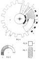
- the toroidal transformer shown has a circularly wound toroid (1), which is divided into two halves by two cuts (2).
- Low-voltage coils (3) which were previously manufactured as air coils, are pushed onto these two ring halves, as shown in FIG. 9.
- an elastic, flexible insulation layer (4) Between the low-voltage coil (3) and the toroidal core (1) there is an elastic, flexible insulation layer (4).
- the two halves of the ring core are each cast separately, although the cut surfaces (2) of the ring cores are still free.
- support elements (8) are then placed on the low-voltage coil (3) when the toroidal halves finished to the low-voltage coil are not cast.
- These support elements determine the position of the high-voltage coils (5, 15) to be pushed on.
- the high-voltage coils (5 and 15) are then pushed over the ring core halves, as can be seen from FIGS. 4 and 5.
- the two toroid halves are on their cut surfaces pressed together and, for example by surface welding, fixed in this position and then cast with casting resin (6).
- the protruding winding disks of the high-voltage windings (5) give rise to ribs (7) which provide good ventilation for the toroidal transformer thus constructed.
- Fig. 10 finally shows an "energy column” formed from three superimposed single toroidal transformers, which are held in this position by a central pressure rod (9) and a resilient clamping ring (8).
Landscapes
- Engineering & Computer Science (AREA)
- Power Engineering (AREA)
- Manufacturing & Machinery (AREA)
- Coils Or Transformers For Communication (AREA)
- Coils Of Transformers For General Uses (AREA)
Priority Applications (3)
| Application Number | Priority Date | Filing Date | Title |
|---|---|---|---|
| ES92103238T ES2076580T3 (es) | 1992-02-26 | 1992-02-26 | Transformador toroidal. |
| DE59203473T DE59203473D1 (de) | 1992-02-26 | 1992-02-26 | Ringkerntransformator. |
| EP19920103238 EP0557549B1 (fr) | 1992-02-26 | 1992-02-26 | Transformateur à noyau annulaire |
Applications Claiming Priority (1)
| Application Number | Priority Date | Filing Date | Title |
|---|---|---|---|
| EP19920103238 EP0557549B1 (fr) | 1992-02-26 | 1992-02-26 | Transformateur à noyau annulaire |
Publications (2)
| Publication Number | Publication Date |
|---|---|
| EP0557549A1 true EP0557549A1 (fr) | 1993-09-01 |
| EP0557549B1 EP0557549B1 (fr) | 1995-08-30 |
Family
ID=8209365
Family Applications (1)
| Application Number | Title | Priority Date | Filing Date |
|---|---|---|---|
| EP19920103238 Expired - Lifetime EP0557549B1 (fr) | 1992-02-26 | 1992-02-26 | Transformateur à noyau annulaire |
Country Status (3)
| Country | Link |
|---|---|
| EP (1) | EP0557549B1 (fr) |
| DE (1) | DE59203473D1 (fr) |
| ES (1) | ES2076580T3 (fr) |
Cited By (9)
| Publication number | Priority date | Publication date | Assignee | Title |
|---|---|---|---|---|
| WO1995011514A1 (fr) * | 1993-10-20 | 1995-04-27 | Ciba Geigy Ag | Transformateur de puissance |
| WO2001020622A1 (fr) * | 1999-09-16 | 2001-03-22 | Philippe Viarouge | Transformateurs de puissance et inductances de puissance pour des applications a basse frequence faisant intervenir des materiaux magnetiques composites isotropes presentant une puissance massique elevee |
| WO2006040074A1 (fr) * | 2004-10-07 | 2006-04-20 | Volker Werner Hanser | Transformateur a noyau toroidal |
| WO2009138096A1 (fr) * | 2008-05-13 | 2009-11-19 | Abb Technology Ag | Transformateur sec |
| WO2009138095A1 (fr) * | 2008-05-13 | 2009-11-19 | Abb Technology Ag | Transformateur sec |
| EP2184749A1 (fr) | 2008-11-08 | 2010-05-12 | ABB Technology AG | Agencement de segments d'enroulement |
| WO2009146835A3 (fr) * | 2008-06-07 | 2010-08-05 | Volker Werner Hanser | Transformateur |
| WO2011014344A1 (fr) * | 2009-07-31 | 2011-02-03 | Abb Technology Ag | Transformateur monté sur un poteau de type sec |
| US12278035B2 (en) | 2019-01-25 | 2025-04-15 | Hun-Ren Energiatudományi Kutatóközpont | Method for insulation of coil of toroid transformers |
Families Citing this family (4)
| Publication number | Priority date | Publication date | Assignee | Title |
|---|---|---|---|---|
| WO2009138100A1 (fr) * | 2008-05-13 | 2009-11-19 | Abb Technology Ag | Enroulement haute tension |
| WO2009138099A1 (fr) * | 2008-05-13 | 2009-11-19 | Abb Technology Ag | Connexion de modules d'enroulements de transformateur |
| CA2723256A1 (fr) | 2008-05-13 | 2009-11-19 | Abb Technology Ag | Noyau toroidal modulaire |
| DE102009017399A1 (de) | 2008-06-07 | 2010-06-24 | Volker Werner Hanser | Transformator |
Citations (2)
| Publication number | Priority date | Publication date | Assignee | Title |
|---|---|---|---|---|
| FR1281532A (fr) * | 1961-01-06 | 1962-01-12 | Bobine d'arrêt pour appareils d'éclairage | |
| DE3613861A1 (de) * | 1986-04-24 | 1987-11-05 | Nkl Naturenergie Und Kleinspan | Geraeuschgedaempftes induktives elektrisches bauelement |
-
1992
- 1992-02-26 EP EP19920103238 patent/EP0557549B1/fr not_active Expired - Lifetime
- 1992-02-26 DE DE59203473T patent/DE59203473D1/de not_active Expired - Fee Related
- 1992-02-26 ES ES92103238T patent/ES2076580T3/es not_active Expired - Lifetime
Patent Citations (2)
| Publication number | Priority date | Publication date | Assignee | Title |
|---|---|---|---|---|
| FR1281532A (fr) * | 1961-01-06 | 1962-01-12 | Bobine d'arrêt pour appareils d'éclairage | |
| DE3613861A1 (de) * | 1986-04-24 | 1987-11-05 | Nkl Naturenergie Und Kleinspan | Geraeuschgedaempftes induktives elektrisches bauelement |
Non-Patent Citations (1)
| Title |
|---|
| PATENT ABSTRACTS OF JAPAN vol. 9, no. 15 (E-291)(1738) 22. Januar 1985 & JP-A-59 161 806 ( OOSAKA HENATSUKI ) 12. September 1984 * |
Cited By (17)
| Publication number | Priority date | Publication date | Assignee | Title |
|---|---|---|---|---|
| WO1995011514A1 (fr) * | 1993-10-20 | 1995-04-27 | Ciba Geigy Ag | Transformateur de puissance |
| WO2001020622A1 (fr) * | 1999-09-16 | 2001-03-22 | Philippe Viarouge | Transformateurs de puissance et inductances de puissance pour des applications a basse frequence faisant intervenir des materiaux magnetiques composites isotropes presentant une puissance massique elevee |
| US6879237B1 (en) | 1999-09-16 | 2005-04-12 | Electrotechnologies Selem Inc. | Power transformers and power inductors for low-frequency applications using isotropic material with high power-to-weight ratio |
| EA012993B1 (ru) * | 2004-10-07 | 2010-02-26 | Фолькер Вернер Ханзер | Способ и устройство для изготовления трансформатора с тороидальными сердечниками |
| AP2125A (en) * | 2004-10-07 | 2010-05-17 | Volker Werner Hanser | Toroidal core transformer |
| EA012485B1 (ru) * | 2004-10-07 | 2009-10-30 | Фолькер Вернер Ханзер | Трансформатор с тороидальными сердечниками |
| WO2006040074A1 (fr) * | 2004-10-07 | 2006-04-20 | Volker Werner Hanser | Transformateur a noyau toroidal |
| EA012992B1 (ru) * | 2004-10-07 | 2010-02-26 | Фолькер Вернер Ханзер | Способ и устройство для изготовления тороидального сердечника для трансформатора с тороидальными сердечниками |
| AU2005293857B2 (en) * | 2004-10-07 | 2009-10-01 | Volker Werner Hanser | Toroidal core transformer |
| WO2009138096A1 (fr) * | 2008-05-13 | 2009-11-19 | Abb Technology Ag | Transformateur sec |
| WO2009138095A1 (fr) * | 2008-05-13 | 2009-11-19 | Abb Technology Ag | Transformateur sec |
| US8310330B2 (en) | 2008-05-13 | 2012-11-13 | Abb Technology Ag | Dry-type transformer |
| WO2009146835A3 (fr) * | 2008-06-07 | 2010-08-05 | Volker Werner Hanser | Transformateur |
| WO2010051911A1 (fr) * | 2008-11-08 | 2010-05-14 | Abb Technology Ag | Agencement de segments bobinés |
| EP2184749A1 (fr) | 2008-11-08 | 2010-05-12 | ABB Technology AG | Agencement de segments d'enroulement |
| WO2011014344A1 (fr) * | 2009-07-31 | 2011-02-03 | Abb Technology Ag | Transformateur monté sur un poteau de type sec |
| US12278035B2 (en) | 2019-01-25 | 2025-04-15 | Hun-Ren Energiatudományi Kutatóközpont | Method for insulation of coil of toroid transformers |
Also Published As
| Publication number | Publication date |
|---|---|
| DE59203473D1 (de) | 1995-10-05 |
| ES2076580T3 (es) | 1995-11-01 |
| EP0557549B1 (fr) | 1995-08-30 |
Similar Documents
| Publication | Publication Date | Title |
|---|---|---|
| EP0557549B1 (fr) | Transformateur à noyau annulaire | |
| DE3011079A1 (de) | Verfahren zur herstellung eines magnetankers geteilten aufbaus und anker nach diesem verfahren | |
| DE69205445T2 (de) | Verfahren zur Erstellung eines statischen, elektromagnetischen Induktors. | |
| EP0102513A1 (fr) | Transformateur à sec avec enroulements fondus dans une résine de coulée | |
| EP0629311A1 (fr) | Bobine pour un transformeur haute tension. | |
| EP0196992A1 (fr) | Transformateur de courant à noyau magnétique rectangulaire | |
| DE19954682C1 (de) | Hochfrequenz-Transformator | |
| EP1041697A2 (fr) | Machine à réluctance avec au moins deux pôles saillants, chacun avec bobinage d'excitation et procédé de fabrication du stator d'une telle machine | |
| DE4417787A1 (de) | Läufer für eine elektrische Drehmaschine und Verfahren zu dessen Herstellung | |
| EP2239745B1 (fr) | Transformateur de performance doté d'un noyau amorphe | |
| EP1869757A1 (fr) | Partie primaire d'un moteur lineaire et moteur lineaire la comprenant | |
| EP0335142A1 (fr) | Transformateur pour réseau de commutation | |
| EP0127119A1 (fr) | Appareil électromagnétique pour circuit de puissance à haute fréquence, en particulier transformateur ou bobine réactance | |
| DE3918187A1 (de) | Eisenkern fuer elektromagnetische geraete | |
| EP3721458B1 (fr) | Appareil électrique muni de plaques de serrage pour serrer un noyau magnétisable | |
| DE2800750A1 (de) | Eisenkern fuer einen hochspannungstransformator niedriger leistung | |
| DE3133626A1 (de) | Elektromotor mit verstaerktem magnetfluss | |
| DE102007017702A1 (de) | Elektrisches Bauteil mit Wicklung und Anzapfung | |
| EP0711450B1 (fr) | Transducteur planaire | |
| DE3636938C2 (fr) | ||
| DE4226764A1 (de) | Drosselspule | |
| DE3322136A1 (de) | Verfahren zur herstellung von magnetkernen fuer transformatoren und drosselspulen mit grossen nennleistungen | |
| DE3030641A1 (de) | Unter einschluss von kleinen eisenteilchen geformter magnetkern und verfahren zur herstellung des magnetkerns | |
| DE2805387A1 (de) | Eisenkern fuer transformatoren, drosselspulen, elektromotoren, generatoren o.dgl. elektrische maschinen | |
| DE2642111A1 (de) | Scheibenfoermiger leistungstransformator fuer die induktive erwaermung von metallischen werkstuecken |
Legal Events
| Date | Code | Title | Description |
|---|---|---|---|
| PUAI | Public reference made under article 153(3) epc to a published international application that has entered the european phase |
Free format text: ORIGINAL CODE: 0009012 |
|
| 17P | Request for examination filed |
Effective date: 19930305 |
|
| AK | Designated contracting states |
Kind code of ref document: A1 Designated state(s): DE ES FR GB IT |
|
| 17Q | First examination report despatched |
Effective date: 19940824 |
|
| RAP1 | Party data changed (applicant data changed or rights of an application transferred) |
Owner name: HANSER, VOLKER |
|
| GRAA | (expected) grant |
Free format text: ORIGINAL CODE: 0009210 |
|
| AK | Designated contracting states |
Kind code of ref document: B1 Designated state(s): DE ES FR GB IT |
|
| GBT | Gb: translation of ep patent filed (gb section 77(6)(a)/1977) |
Effective date: 19950830 |
|
| REF | Corresponds to: |
Ref document number: 59203473 Country of ref document: DE Date of ref document: 19951005 |
|
| REG | Reference to a national code |
Ref country code: ES Ref legal event code: FG2A Ref document number: 2076580 Country of ref document: ES Kind code of ref document: T3 |
|
| ITF | It: translation for a ep patent filed | ||
| ET | Fr: translation filed | ||
| PLBE | No opposition filed within time limit |
Free format text: ORIGINAL CODE: 0009261 |
|
| STAA | Information on the status of an ep patent application or granted ep patent |
Free format text: STATUS: NO OPPOSITION FILED WITHIN TIME LIMIT |
|
| 26N | No opposition filed | ||
| REG | Reference to a national code |
Ref country code: GB Ref legal event code: IF02 |
|
| PGFP | Annual fee paid to national office [announced via postgrant information from national office to epo] |
Ref country code: GB Payment date: 20020204 Year of fee payment: 11 |
|
| PGFP | Annual fee paid to national office [announced via postgrant information from national office to epo] |
Ref country code: FR Payment date: 20020221 Year of fee payment: 11 Ref country code: ES Payment date: 20020221 Year of fee payment: 11 |
|
| PGFP | Annual fee paid to national office [announced via postgrant information from national office to epo] |
Ref country code: DE Payment date: 20020430 Year of fee payment: 11 |
|
| PG25 | Lapsed in a contracting state [announced via postgrant information from national office to epo] |
Ref country code: GB Free format text: LAPSE BECAUSE OF NON-PAYMENT OF DUE FEES Effective date: 20030226 |
|
| PG25 | Lapsed in a contracting state [announced via postgrant information from national office to epo] |
Ref country code: ES Free format text: LAPSE BECAUSE OF NON-PAYMENT OF DUE FEES Effective date: 20030227 |
|
| PG25 | Lapsed in a contracting state [announced via postgrant information from national office to epo] |
Ref country code: DE Free format text: LAPSE BECAUSE OF NON-PAYMENT OF DUE FEES Effective date: 20030902 |
|
| GBPC | Gb: european patent ceased through non-payment of renewal fee | ||
| PG25 | Lapsed in a contracting state [announced via postgrant information from national office to epo] |
Ref country code: FR Free format text: LAPSE BECAUSE OF NON-PAYMENT OF DUE FEES Effective date: 20031031 |
|
| REG | Reference to a national code |
Ref country code: FR Ref legal event code: ST |
|
| REG | Reference to a national code |
Ref country code: ES Ref legal event code: FD2A Effective date: 20030227 |
|
| PG25 | Lapsed in a contracting state [announced via postgrant information from national office to epo] |
Ref country code: IT Free format text: LAPSE BECAUSE OF NON-PAYMENT OF DUE FEES;WARNING: LAPSES OF ITALIAN PATENTS WITH EFFECTIVE DATE BEFORE 2007 MAY HAVE OCCURRED AT ANY TIME BEFORE 2007. THE CORRECT EFFECTIVE DATE MAY BE DIFFERENT FROM THE ONE RECORDED. Effective date: 20050226 |