EP0557610A2 - Système de tuyau - Google Patents
Système de tuyau Download PDFInfo
- Publication number
- EP0557610A2 EP0557610A2 EP92121549A EP92121549A EP0557610A2 EP 0557610 A2 EP0557610 A2 EP 0557610A2 EP 92121549 A EP92121549 A EP 92121549A EP 92121549 A EP92121549 A EP 92121549A EP 0557610 A2 EP0557610 A2 EP 0557610A2
- Authority
- EP
- European Patent Office
- Prior art keywords
- line
- pipe system
- pipe
- parts
- designed
- Prior art date
- Legal status (The legal status is an assumption and is not a legal conclusion. Google has not performed a legal analysis and makes no representation as to the accuracy of the status listed.)
- Granted
Links
Images


Classifications
-
- F—MECHANICAL ENGINEERING; LIGHTING; HEATING; WEAPONS; BLASTING
- F16—ENGINEERING ELEMENTS AND UNITS; GENERAL MEASURES FOR PRODUCING AND MAINTAINING EFFECTIVE FUNCTIONING OF MACHINES OR INSTALLATIONS; THERMAL INSULATION IN GENERAL
- F16L—PIPES; JOINTS OR FITTINGS FOR PIPES; SUPPORTS FOR PIPES, CABLES OR PROTECTIVE TUBING; MEANS FOR THERMAL INSULATION IN GENERAL
- F16L39/00—Joints or fittings for double-walled or multi-channel pipes or pipe assemblies
- F16L39/04—Joints or fittings for double-walled or multi-channel pipes or pipe assemblies allowing adjustment or movement
-
- Y—GENERAL TAGGING OF NEW TECHNOLOGICAL DEVELOPMENTS; GENERAL TAGGING OF CROSS-SECTIONAL TECHNOLOGIES SPANNING OVER SEVERAL SECTIONS OF THE IPC; TECHNICAL SUBJECTS COVERED BY FORMER USPC CROSS-REFERENCE ART COLLECTIONS [XRACs] AND DIGESTS
- Y10—TECHNICAL SUBJECTS COVERED BY FORMER USPC
- Y10S—TECHNICAL SUBJECTS COVERED BY FORMER USPC CROSS-REFERENCE ART COLLECTIONS [XRACs] AND DIGESTS
- Y10S285/00—Pipe joints or couplings
- Y10S285/906—Equivalents
Definitions
- the invention is based on a pipe system for hydraulic systems according to the preamble of claim 1.
- FIG. 1 shows a schematic illustration of control servomotors 1, 2, 3 which are seated on a turbine housing 4.
- the valve housing of the valves, which are actuated by these control servomotors 1, 2, 3, are arranged here in the interior of the turbine housing 4.
- the control servo motors 1, 2, 3 are operated hydraulically. Via an actuating line 5, which has a pressurized supply line on the inside, oil is supplied under pressure for actuating the servomotors 1, 2, 3. This feed line is enclosed by a drain line for the oil leaving the servomotors 1, 2, 3 and flowing into the outlet.
- actuating line 5 consisting of two lines is flanged to a connecting part 6.
- the connecting parts 6, 8 and 10 are advantageously dimensioned the same and, as can be seen from FIGS. 2 and 3, they contain T-shaped lines, of which the inner line 12 is designed as part of the pressurized supply line.
- the outer line 13, which surrounds the inner line 12, is designed as part of the drain line.
- This arrangement of the two lines 12, 13 is maintained through the connecting parts 6, 8, 10 through to the hydraulically actuated devices, such as here in the control servomotors 1, 2, 3, where a piston is usually supplied by the oil fed in under pressure -Cylinder arrangement is actuated.
- This consistently maintained routing of the pressurized supply line ensures that that any leaks in this supply line cannot trigger any major consequential damage to the system, such as fires.
- connecting parts 6 and 10 can be seen, in which the internal line 12 is cast in one piece into the respective connecting parts. However, it is possible to press this inner line 12 together from corresponding pipe parts in a pressure-tight manner and then to fix this line in the respective connecting part.
- Adjacent connecting parts are connected to one another by intermediate pieces 7 and 9.
- These intermediate pieces 7, 9 are designed such that they can compensate for unavoidable manufacturing tolerances and / or thermal expansions in this area both in the axial and somewhat in the radial direction.
- These intermediate pieces 7, 9 can be made in one or two parts.
- 2 shows an integrally formed intermediate piece 7, which connects the connecting parts 6 and 10 to one another in a pressure-tight manner.
- the intermediate piece 7 has two flanges 14, 15 at the ends.
- An outer pipe socket 16 is welded to each of the flanges.
- the ends of the two pipe sockets 16 are connected by means of a pressure-tight, welded, elastic steel bellows 17. Openings 18, 19 are provided in the flanges 14, 15, which allow the oil to flow through the drain.
- the flanges 14 and 15 are screwed to the corresponding connecting parts 6 and 10 in a pressure-tight manner. Sealing rings arranged in a known manner, which are not described in detail here ensure this tightness.
- the flanges 14 and 15 are also provided in the center with connecting pieces 22 which protrude into the inner lines 12 of the connecting parts 6 and 10 and are connected to these lines 12 in a pressure-tight manner by means of sealing rings.
- the nozzles 22 are so long that the tightness is guaranteed in any case.
- the flange connection between the connection part 6 and a housing 23 of the associated control servo motor is also sealed by means of a sealing ring, as is the corresponding connection between the connection part 10 and a housing 24 of the corresponding control servo motor.
- the actuating line 5 is mechanically sufficiently stable, so that damage to this line is almost impossible under normal circumstances.
- the internal supply line for the oil under pressure is therefore also well protected.
- the only mechanical weak point in this pipe system is the steel bellows 17 in the intermediate piece 7.
- a protective tube 25 is provided which is connected to the flange 15 and which covers this steel bellows 17.
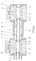
- the arrangement according to FIG. 3 differs from that according to FIG. 2 only in that the intermediate piece 7 consists of two parts.
- the feed line is guided through the intermediate piece 7 in a separate tube 26 which is not connected to the flanges 14, 15.
- the ends of this tube 26 protrude into the inner lines 12 of the connecting parts 6 and 10 and are connected to these lines 12 in a pressure-tight manner by means of sealing rings.
- a stop 27 within the lines 12 prevents the tube 26 from slipping, so that the tightness is guaranteed in any case.
- the oil leaving the cylinder-piston arrangement is passed through the discharge line, which surrounds the supply line for the oil under pressure, into the respective housing 23, 24 and further into the external line 13 in the connection housings 6, 10. From there, the oil flows, partly through the openings 18, 19 and the intermediate piece 7, further into the external drain line of the actuation line 5. The oil is led into the drain through this line 5.
- This piping system offers a high degree of operational safety, especially when operating control servo motors in the area of steam turbines.
Landscapes
- Engineering & Computer Science (AREA)
- General Engineering & Computer Science (AREA)
- Mechanical Engineering (AREA)
- Joints Allowing Movement (AREA)
Applications Claiming Priority (2)
| Application Number | Priority Date | Filing Date | Title |
|---|---|---|---|
| DE4204530 | 1992-02-15 | ||
| DE4204530A DE4204530A1 (de) | 1992-02-15 | 1992-02-15 | Rohrsystem |
Publications (3)
| Publication Number | Publication Date |
|---|---|
| EP0557610A2 true EP0557610A2 (fr) | 1993-09-01 |
| EP0557610A3 EP0557610A3 (en) | 1993-11-10 |
| EP0557610B1 EP0557610B1 (fr) | 1996-03-27 |
Family
ID=6451776
Family Applications (1)
| Application Number | Title | Priority Date | Filing Date |
|---|---|---|---|
| EP92121549A Expired - Lifetime EP0557610B1 (fr) | 1992-02-15 | 1992-12-18 | Système de tuyau |
Country Status (3)
| Country | Link |
|---|---|
| US (1) | US5427419A (fr) |
| EP (1) | EP0557610B1 (fr) |
| DE (2) | DE4204530A1 (fr) |
Families Citing this family (14)
| Publication number | Priority date | Publication date | Assignee | Title |
|---|---|---|---|---|
| US5778872A (en) * | 1996-11-18 | 1998-07-14 | Medlis, Inc. | Artificial ventilation system and methods of controlling carbon dioxide rebreathing |
| FR2766233B1 (fr) * | 1997-07-21 | 2001-12-07 | Gec Alsthom Electromec | Dispositif etanche pour le raccordement entre la gaine d'arrivee de vapeur et le corps interne de l'ensemble basse-pression d'une turbine a vapeur |
| US6390137B1 (en) * | 2000-06-20 | 2002-05-21 | Ti Group Automotive Systems, Llc | Co-tube assembly for heating and air conditioning system |
| US6550815B2 (en) * | 2001-08-14 | 2003-04-22 | Itt Manufacturing Enterprises, Inc. | Coaxial quick connector |
| US6606865B2 (en) * | 2001-10-31 | 2003-08-19 | General Electric Company | Bellows type outer crossfire tube |
| DE102004021799B3 (de) * | 2004-05-03 | 2005-12-29 | Mtu Friedrichshafen Gmbh | Abgas-Kompensator |
| WO2007019551A2 (fr) * | 2005-08-08 | 2007-02-15 | Hose Master Inc. | Ensemble tuyau gaine et procede |
| US8079220B2 (en) * | 2008-08-28 | 2011-12-20 | Delavan Inc | Fuel distribution manifold system for gas turbine engines |
| CN201753815U (zh) * | 2010-07-27 | 2011-03-02 | 江森自控空调冷冻设备(无锡)有限公司 | 三通结构 |
| US9194297B2 (en) | 2010-12-08 | 2015-11-24 | Parker-Hannifin Corporation | Multiple circuit fuel manifold |
| US9958093B2 (en) | 2010-12-08 | 2018-05-01 | Parker-Hannifin Corporation | Flexible hose assembly with multiple flow passages |
| US9784187B2 (en) * | 2012-06-15 | 2017-10-10 | General Electric Company | Two flow path fuel conduit of a gas turbine engine |
| US9772054B2 (en) | 2013-03-15 | 2017-09-26 | Parker-Hannifin Corporation | Concentric flexible hose assembly |
| US9874351B2 (en) | 2015-04-14 | 2018-01-23 | General Electric Company | Thermally-coupled fuel manifold |
Family Cites Families (18)
| Publication number | Priority date | Publication date | Assignee | Title |
|---|---|---|---|---|
| DE399192C (de) * | 1920-05-31 | 1924-07-28 | Cfcmug | Rohrverbindung fuer konzentrisch ineinanderliegende Rohrleitungen |
| US2196766A (en) * | 1937-07-10 | 1940-04-09 | Eastman Kodak Co | Expansion joint |
| GB578010A (en) * | 1941-11-21 | 1946-06-12 | Frank Bernard Halford | Improvements in jet propulsion plant |
| US2366809A (en) * | 1943-02-24 | 1945-01-09 | Union Carbide & Carbon Corp | Adjustable multiple connection |
| US2658527A (en) * | 1943-11-22 | 1953-11-10 | Edward W Kaiser | Conduit system |
| US2475635A (en) * | 1945-01-08 | 1949-07-12 | Elmer C Parsons | Multiple conduit |
| US2490515A (en) * | 1945-02-05 | 1949-12-06 | Oilgear Co | Power transmission and support therefor |
| US2956586A (en) * | 1959-09-03 | 1960-10-18 | Gen Motors Corp | Hose arrangement |
| US3878868A (en) * | 1973-12-14 | 1975-04-22 | Gen Electric | Expansion joint |
| DE2525693A1 (de) * | 1975-06-10 | 1976-12-30 | Berg Fritz Hinrich Dipl Ing | Verbindung fuer schutzummantelungen |
| US4099746A (en) * | 1975-09-16 | 1978-07-11 | Siemens Aktiengesellschaft | Equalizing arrangement for a low temperature line |
| DE2739114A1 (de) * | 1977-08-31 | 1979-03-08 | Pforzheim Metallschlauch | Hochdruckkompensator fuer rohrleitungen |
| DE2739124C3 (de) * | 1977-08-31 | 1980-07-03 | Westfaelische Metall Industrie Kg, Hueck & Co, 4780 Lippstadt | Prüfgerät für Fahrzeugscheinwerfer |
| DE3619630A1 (de) * | 1986-06-11 | 1987-12-17 | Hoechst Ag | Sicherheitsdrehdurchfuehrung |
| US4922971A (en) * | 1986-09-23 | 1990-05-08 | Dayco Products, Inc. | Hose assembly, clip therefor and method of making the same |
| DE3761843D1 (de) * | 1986-11-18 | 1990-04-12 | Smc Corp | Antriebssystem fuer stellorgane. |
| US4886305A (en) * | 1988-08-12 | 1989-12-12 | Fibercast Company | Double containment pipe fittings and apparatus to adhesively install the same |
| US5203384A (en) * | 1990-08-15 | 1993-04-20 | Dresser Industries, Inc. | Combination casting for a blending dispenser |
-
1992
- 1992-02-15 DE DE4204530A patent/DE4204530A1/de not_active Withdrawn
- 1992-12-18 DE DE59205860T patent/DE59205860D1/de not_active Expired - Fee Related
- 1992-12-18 EP EP92121549A patent/EP0557610B1/fr not_active Expired - Lifetime
-
1993
- 1993-01-19 US US08/005,782 patent/US5427419A/en not_active Expired - Fee Related
Also Published As
| Publication number | Publication date |
|---|---|
| US5427419A (en) | 1995-06-27 |
| EP0557610A3 (en) | 1993-11-10 |
| EP0557610B1 (fr) | 1996-03-27 |
| DE4204530A1 (de) | 1993-08-19 |
| DE59205860D1 (de) | 1996-05-02 |
Similar Documents
| Publication | Publication Date | Title |
|---|---|---|
| EP0557610B1 (fr) | Système de tuyau | |
| DE102007037995B4 (de) | Koaxialventil mit einem elektrischen Antrieb | |
| EP0507127B1 (fr) | Distributeur à tube | |
| DE2709633A1 (de) | Verfahren und vorrichtung zum befestigen einer muffe in einer fluid-rohrleitung | |
| EP0094439B1 (fr) | Raccord à soupape pour système fluidique | |
| DE9403603U1 (de) | Ausblaseinheit für Absperrschieber in Rohrleitungen | |
| EP0884506A2 (fr) | Raccorderie, notamment clapet de réglage et d'arrêt | |
| EP1223118B1 (fr) | Vanne pour le soufflage d' air comprimé par impulsion pour éliminer les amas de materiau. | |
| EP0984216B1 (fr) | Dispositif de fermeture pour conduit | |
| DE2915432A1 (de) | Ventilstellglied | |
| DE19901257C1 (de) | Regelventil für Tieftemperatur-Einsatz | |
| EP0852681B1 (fr) | Circuit hydraulique a retour integre sans pression | |
| DE4411050A1 (de) | Kugelhahn | |
| AT412114B (de) | Doppeltwirkender arbeitszylinder | |
| DD267541A5 (de) | Schnellschluss-absperrschieber | |
| DE2107987A1 (de) | Kupplung fur Vielfachrohrleitungen | |
| DE3642303A1 (de) | Ventil mit druckentlastetem ventilglied | |
| DE3208908C1 (de) | Kugelhahn für Rohrleitungen großer Nennweiten | |
| DE3818859A1 (de) | Sicherheitsabsperreinrichtung | |
| DE4112448C2 (de) | Hochdruckstopfbuchse | |
| DE3245688A1 (de) | Absperrventil fuer heisse gase | |
| DE1775464B1 (de) | Ringfoermige Anordnung druckmittelbetaetigter Klappen zur Querschnittsveraenderung von Stroemungskanaelen,insbesondere fuer Triebwerksschubduesen | |
| EP0462392B1 (fr) | Vanne hydraulique | |
| DE102004012599A1 (de) | Druckentlastung einer Flanschverbindung in Überströmleitungen zwischen Frischdampfventil und HD-Dampfturbineneintritt | |
| EP1223117A1 (fr) | Dispositif de type canon à air comprimé pour éliminer les amas de matériau |
Legal Events
| Date | Code | Title | Description |
|---|---|---|---|
| PUAI | Public reference made under article 153(3) epc to a published international application that has entered the european phase |
Free format text: ORIGINAL CODE: 0009012 |
|
| AK | Designated contracting states |
Kind code of ref document: A2 Designated state(s): DE FR GB |
|
| PUAL | Search report despatched |
Free format text: ORIGINAL CODE: 0009013 |
|
| AK | Designated contracting states |
Kind code of ref document: A3 Designated state(s): DE FR GB |
|
| 17P | Request for examination filed |
Effective date: 19940416 |
|
| 17Q | First examination report despatched |
Effective date: 19950831 |
|
| GRAA | (expected) grant |
Free format text: ORIGINAL CODE: 0009210 |
|
| AK | Designated contracting states |
Kind code of ref document: B1 Designated state(s): DE FR GB |
|
| REF | Corresponds to: |
Ref document number: 59205860 Country of ref document: DE Date of ref document: 19960502 |
|
| GBT | Gb: translation of ep patent filed (gb section 77(6)(a)/1977) |
Effective date: 19960531 |
|
| ET | Fr: translation filed | ||
| PGFP | Annual fee paid to national office [announced via postgrant information from national office to epo] |
Ref country code: GB Payment date: 19961113 Year of fee payment: 5 |
|
| PGFP | Annual fee paid to national office [announced via postgrant information from national office to epo] |
Ref country code: FR Payment date: 19961118 Year of fee payment: 5 |
|
| PGFP | Annual fee paid to national office [announced via postgrant information from national office to epo] |
Ref country code: DE Payment date: 19961207 Year of fee payment: 5 |
|
| PLBE | No opposition filed within time limit |
Free format text: ORIGINAL CODE: 0009261 |
|
| STAA | Information on the status of an ep patent application or granted ep patent |
Free format text: STATUS: NO OPPOSITION FILED WITHIN TIME LIMIT |
|
| 26N | No opposition filed | ||
| PG25 | Lapsed in a contracting state [announced via postgrant information from national office to epo] |
Ref country code: GB Free format text: LAPSE BECAUSE OF NON-PAYMENT OF DUE FEES Effective date: 19971218 |
|
| PG25 | Lapsed in a contracting state [announced via postgrant information from national office to epo] |
Ref country code: FR Free format text: THE PATENT HAS BEEN ANNULLED BY A DECISION OF A NATIONAL AUTHORITY Effective date: 19971231 |
|
| GBPC | Gb: european patent ceased through non-payment of renewal fee |
Effective date: 19971218 |
|
| PG25 | Lapsed in a contracting state [announced via postgrant information from national office to epo] |
Ref country code: DE Free format text: LAPSE BECAUSE OF NON-PAYMENT OF DUE FEES Effective date: 19980901 |
|
| REG | Reference to a national code |
Ref country code: FR Ref legal event code: ST |