EP0557631A1 - Cycle ambiant maximum - Google Patents
Cycle ambiant maximum Download PDFInfo
- Publication number
- EP0557631A1 EP0557631A1 EP92301717A EP92301717A EP0557631A1 EP 0557631 A1 EP0557631 A1 EP 0557631A1 EP 92301717 A EP92301717 A EP 92301717A EP 92301717 A EP92301717 A EP 92301717A EP 0557631 A1 EP0557631 A1 EP 0557631A1
- Authority
- EP
- European Patent Office
- Prior art keywords
- compressor
- fluid
- turbine
- temperature
- reservoir
- Prior art date
- Legal status (The legal status is an assumption and is not a legal conclusion. Google has not performed a legal analysis and makes no representation as to the accuracy of the status listed.)
- Ceased
Links
Images

Classifications
-
- F—MECHANICAL ENGINEERING; LIGHTING; HEATING; WEAPONS; BLASTING
- F02—COMBUSTION ENGINES; HOT-GAS OR COMBUSTION-PRODUCT ENGINE PLANTS
- F02C—GAS-TURBINE PLANTS; AIR INTAKES FOR JET-PROPULSION PLANTS; CONTROLLING FUEL SUPPLY IN AIR-BREATHING JET-PROPULSION PLANTS
- F02C1/00—Gas-turbine plants characterised by the use of hot gases or unheated pressurised gases, as the working fluid
- F02C1/04—Gas-turbine plants characterised by the use of hot gases or unheated pressurised gases, as the working fluid the working fluid being heated indirectly
- F02C1/10—Closed cycles
-
- F—MECHANICAL ENGINEERING; LIGHTING; HEATING; WEAPONS; BLASTING
- F03—MACHINES OR ENGINES FOR LIQUIDS; WIND, SPRING, OR WEIGHT MOTORS; PRODUCING MECHANICAL POWER OR A REACTIVE PROPULSIVE THRUST, NOT OTHERWISE PROVIDED FOR
- F03G—SPRING, WEIGHT, INERTIA OR LIKE MOTORS; MECHANICAL-POWER PRODUCING DEVICES OR MECHANISMS, NOT OTHERWISE PROVIDED FOR OR USING ENERGY SOURCES NOT OTHERWISE PROVIDED FOR
- F03G7/00—Mechanical-power-producing mechanisms, not otherwise provided for or using energy sources not otherwise provided for
- F03G7/10—Alleged perpetua mobilia
- F03G7/122—Alleged perpetua mobilia of closed energy loops
-
- F—MECHANICAL ENGINEERING; LIGHTING; HEATING; WEAPONS; BLASTING
- F03—MACHINES OR ENGINES FOR LIQUIDS; WIND, SPRING, OR WEIGHT MOTORS; PRODUCING MECHANICAL POWER OR A REACTIVE PROPULSIVE THRUST, NOT OTHERWISE PROVIDED FOR
- F03G—SPRING, WEIGHT, INERTIA OR LIKE MOTORS; MECHANICAL-POWER PRODUCING DEVICES OR MECHANISMS, NOT OTHERWISE PROVIDED FOR OR USING ENERGY SOURCES NOT OTHERWISE PROVIDED FOR
- F03G7/00—Mechanical-power-producing mechanisms, not otherwise provided for or using energy sources not otherwise provided for
- F03G7/10—Alleged perpetua mobilia
- F03G7/129—Thermodynamic processes
Definitions
- This invention relates to work producing cycles and more particularly, to a high efficiency system that interacts with ambient conditions to maintain thermal equilibrium using a working fluid in connection with a turbine, a compressor and a heat exchange mechanism wherein turbine exhaust is used to reduce compressor work by isothermal compression and the turbine exhaust's internal energy is restored as a collateral result, and work is derived from an adiabatic internal energy change starting at ambient temperature.
- a conventional system for developing a power cycle typically comprises a boiler, turbine, condenser and pump.
- Heat is supplied to the boiler by a fossil fuel to convert an operating fluid into a high pressure vapor or gas for use as the working medium.
- the vapor is expanded in the turbine to produce a work output.
- exhaust vapor from the turbine enters the condenser wherein sufficient heat is removed to condense the vapor.
- Saturated liquid is delivered to a pump, which raises the pressure to the saturation pressure corresponding to the boiler temperature and thereafter the liquid is delivered to the boiler where the cycle repeats.
- Standard systems use a heat source and heat sink to establish a temperature gradient to create heat flow. With a temperature differential created, a working fluid is caused to flow as a result of pressure and/or volumetric differential.
- the applicability of any system hinges on the efficiency of the cycle.
- One apparent flaw in prior art systems is the fact that high work input is a necessary result of creating a differential by developing very high pressures and temperatures through the addition of heat.
- the amount of work required to compress the vapor back to its saturation pressure has been greater than the work extracted from the system through the turbine.
- the work input that is required to compress the vapor is functionally dependent upon a temperature differential established to generate heat flow in the system.
- efforts have been made to improve efficiency by utilizing latent or waste heat to reduce heat input.
- a principal objective of the present invention is to provide a system wherein the operating medium is Pressurized in the cycle while consuming a minimal amount of the work produced by expansion of the operating medium.
- vapor is cooled during the compression portion of the cycle simultaneously as compression of the operating medium is being carried out. As a result, compression work is minimized. Additional cooling may be performed by standard A/C techniques.
- the invention also contemplates input heat reduction by using ambient air as a heat exchange medium.
- ambient air As a heat exchange medium.
- prior art power cycles heat an operating fluid above ambient temperature to produce a temperature differential
- the present invention contemplates a cycle wherein the working fluid is maintained at or near ambient temperature.
- the ambient temperature may be approximately 80°F. Accordingly the heat input is substantially reduced over the input required in conventional power cycle systems.
- the fluid circuit of the invention comprises a turbine for producing a work output in which the working fluid comes in at an incoming temperature and pressure and is exhausted at a first temperature and pressure below the incoming temperature and pressure; a compressor downstream of the turbine; first means for effecting heat exchange between the fluid from the turbine that is exhausted at said first temperature and the compressor so that the fluid in the compressor is cooled and the exhaust fluid from the turbine heated by the compressor through heat exchange therewith to a temperature above the first temperature; a reservoir for working fluid from the turbine heated by the compressor to the reservoir; means for delivering fluid from the reservoir to the compressor for compression thereby; a second reservoir; means for delivering fluid compressed by the compressor to the second reservoir; and means for delivering fluid from the second reservoir to the turbine.
- the present system comprises a high pressure gas reservoir, a turbine, a compressor, a low pressure reservoir, a heat exchanger and flow control structure such as valves, etc.
- the high pressure reservoir is in heat exchange relationship with ambient air and delivers fluid at ambient temperature to a turbine.
- Spent fluid from the turbine is brought into heat exchange relationship with the compressor which is at a temperature above that of the exhaust fluid.
- the compressed vapor is thus maintained at a temperature below that which it would normally be at in a conventional compression operation.
- the turbine exhaust which is heated by the compressor, is then delivered to a low pressure reservoir, which is in heat exchange relationship with ambient air, and from there the fluid is delivered to the compressor inlet, the fluid is compressed in the compressor, and the fluid is directed back to the high pressure reservoir.
- Internal energy is used to provide external work by an adiabatic expansion. No heat flow, per se, is required to accomplish this work output as the work results from a decrease in internal energy with a resulting drop in temperature. The initial internal energy is restored by another internal process that raises the temperature to the starting point as shall be demonstrated. Maximum internal energy is transformable as long as the critical pressure ratio can be utilized by an approximate two to one expansion ratio without drawing upon external heat by use of Curtis stage and impulse stage turbines.
- adiabatic compression is the preferred method to remove heat from an evaporator. This is because the aim of the system is to remove heat from a low to a higher temperature.
- the elevated pressure occasions an increase in temperature or sufficient temperature differential above ambient to make the system feasible.
- isothermal compression has had limited success in input work reduction because the cooling is limited to the ambient conditions.
- compression starts at ambient temperature and would normally increase in temperature, however turbine exhaust is used to cool the process.
- the turbine exhaust which starts at ambient temperature and is adiabatically expanded is considerably below the ambient temperature, and isothermal compression is possible. Internal energy of the compression process remains constant.
- thermodynamic device For work to be produced by a thermodynamic device, heat must pass from a high temperature level (source) to a low temperature level (sink).
- the invention satisfies this requirement.
- the purpose of the compressor in the cycle is to remove or pump effluent out of the evaporator as fast as it flows in to prevent pressure and/or temperature increases(s).
- Thermodynamics does not specify or limit the type of sink or surrounding serving as the low temperature receiver. It may be ambient conditions or another system, and in this instance is the internal heat exchanger and compression processes.
- thermodynamicists when using the Kelvin-Planck statement of the Second Law of Thermodynamics to deny a device's operability draw a boundary around the total system(s) and state that since no heat enters the system(s) no net work can result. Fenn resolves the dilemma when he states, Id. page 15, " Work is not energy. Work is not 'possessed' by a system whereas energy is. Work is something that 'happens' to a system. It is what we call an interaction. A system has energy, but it performs work as an interaction by which the system changes its energy. We cannot say that a system 'contains' so much work so we can represent an amount of work by a change in the 'work content' of a system.
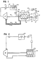
- a system according to the invention is shown schematically and comprises a compressor 10, a high pressure reservoir 12, a turbine 14 and a low pressure reservoir 16.
- the compressor 10 is surrounded by a cooling jacket 18 and has disposed peripherally therearound helically wound cooling flights 20.
- Valves 22, 24, 26, 28 are installed through the system to control the fluid flow volume and pressure throughout the system.
- FREON R-22 refrigerant FREON is a registered trademark for fluorocarbon refrigerant owned by E.I. DuPont De Nemours & Co.
- Pressurized vapor is delivered through valve 26 and conduit 30 to reservoir 12.
- the high pressure reservoir 12 has a heat exchanger 32 to equalize the temperature within the high pressure reservoir 12 and the ambient temperature.
- the fluid is delivered through conduit 34 and valve 28 to the turbine 14.
- the fluid is expanded.
- Work is extracted by any of a number of conventional power take-off devices connected as by drive shafts (not shown) to the turbine output shaft 35.
- the shaft 35 also drives the compressor 10.
- Exhaust fluid from the turbine is delivered through conduit 36 to a chamber 37 inside the cooling jacket 18 surrounding the compressor 10.
- an insulating layer 38 surrounds the conduit 36 communicating between the turbine and chamber 37 within the cooling jacket 18.
- the incoming exhaust fluid surrounding the compressor is at a lower temperature than the fluid in the compressor 10. Heat exchange with the compressor is enhanced by the provision of the flights 20 about the compressor 10.
- the fluid exhausted from the turbine after being heated by the compressor, is delivered through a conduit 40 and valve 24 into the low pressure reservoir 16. Heat exchange between the low pressure reservoir and ambient air is effected through a heat exchange element 42 within the low pressure reservoir 16.
- Fluid is delivered from the low pressure reservoir 16 to the compressor inlet 43 through a conduit 44 and valve 22.
- the compressor pressurizes the fluid from the low pressure reservoir and delivers the same to the high pressure reservoir through conduit 30 and valve 26 for completion of the fluid circuit.
- means 45 for providing the system with any required work or heat to keep the system in continuous operation. These means 45 may be placed throughout the system, and where needed, and the placement of these means 45 is not definitive, only illustrative.
- Fig. 1 The cycle of Fig. 1 is illustrated graphically in Fig. 3 with the temperature represented on the Y axis and pressure on the X axis.
- Line AB represents the compression stage, which occurs at a constant temperature, T1 or ambient temperature. Expansion in the turbine is indicated by the line BC. Compressor cooling and reheating of the turbine exhaust is accomplished through heat exchange with ambient air and is indicated by line CA.
- Fig. 1 The cycle of Fig. 1 is illustrated graphically in Fig. 4 with the temperature represented on the Y axis and entropy on the X axis.
- entropy (S) equals .2250 and enthalpy (H) equals 114 BTU/LB.
- Line AB represents turbine expansion.
- S equals .2250 and H equals 106 BTU/LB. and the pressure equals 56 psia.
- Line BC represents the heat exchange between turbine exhaust and the compressor 10.
- S equals .2443 and H equals 116 BTU/LB.
- Line CA represents isothermal compression as performed in this cycle.
- Line CD shows isentropic compression and at point D, H equals 124.7 BTU/LB. at 110 psia.
- Line DA represents the cooling portion of the cycle in the adiabatic compressor.
- FIG. 2 A modified system according to the invention is shown in Fig. 2.
- the system comprises, as the system in Fig. 1, a high pressure reservoir 46, a turbine 48 and compressor 50.
- the distinction in the system in Fig. 2 is that the compressor is enclosed within a low pressure receiving chamber 52 which obviates the requirement of a separate, low pressure reservoir as in the Fig. 1 system.
- the system in Fig. 2 operates as the system in Fig. 1.
- the cycle of the present invention is characterized by extraordinary high efficiency and as being non-polluting and operable without exhaustion of finite resources.
- a practical feature of the invention is that the apparatus may be assembled, for the most part utilizing "off the shelf” components which are presently available.
Landscapes
- Engineering & Computer Science (AREA)
- Chemical & Material Sciences (AREA)
- Combustion & Propulsion (AREA)
- Mechanical Engineering (AREA)
- General Engineering & Computer Science (AREA)
- Engine Equipment That Uses Special Cycles (AREA)
Applications Claiming Priority (2)
| Application Number | Priority Date | Filing Date | Title |
|---|---|---|---|
| US94044986A | 1986-12-11 | 1986-12-11 | |
| US07/462,723 US5107682A (en) | 1986-12-11 | 1990-01-09 | Maximum ambient cycle |
Publications (1)
| Publication Number | Publication Date |
|---|---|
| EP0557631A1 true EP0557631A1 (fr) | 1993-09-01 |
Family
ID=27040426
Family Applications (1)
| Application Number | Title | Priority Date | Filing Date |
|---|---|---|---|
| EP92301717A Ceased EP0557631A1 (fr) | 1986-12-11 | 1992-02-28 | Cycle ambiant maximum |
Country Status (4)
| Country | Link |
|---|---|
| US (1) | US5107682A (fr) |
| EP (1) | EP0557631A1 (fr) |
| AU (1) | AU642586B2 (fr) |
| BR (1) | BR9200738A (fr) |
Cited By (3)
| Publication number | Priority date | Publication date | Assignee | Title |
|---|---|---|---|---|
| WO1997049908A1 (fr) * | 1996-06-26 | 1997-12-31 | Jamuca Feliks | Moteur a combustion interne a piston rotatif |
| ES2146517A1 (es) * | 1997-07-24 | 2000-08-01 | Landa Axpe Francisco J | Procedimiento para la produccion de energia. |
| WO2006037291A1 (fr) * | 2004-10-01 | 2006-04-13 | Martin Ziegler | Procedes et dispositifs pour utiliser de l'energie thermique, et leurs applications |
Families Citing this family (18)
| Publication number | Priority date | Publication date | Assignee | Title |
|---|---|---|---|---|
| US7926276B1 (en) * | 1992-08-07 | 2011-04-19 | The United States Of America As Represented By The Secretary Of The Navy | Closed cycle Brayton propulsion system with direct heat transfer |
| US5626459A (en) * | 1992-10-13 | 1997-05-06 | Cosby; Thomas L. | Unitary turbine/compressor engine |
| FR2717253B1 (fr) * | 1994-03-08 | 1999-12-24 | Rotoflow Corp | Dissipateur d'énergie sans contamination et procédé d'optimisation du fonctionnement de turbodétendeurs. |
| US5904044A (en) * | 1997-02-19 | 1999-05-18 | White; William M. | Fluid expander |
| US7841306B2 (en) * | 2007-04-16 | 2010-11-30 | Calnetix Power Solutions, Inc. | Recovering heat energy |
| US8839622B2 (en) | 2007-04-16 | 2014-09-23 | General Electric Company | Fluid flow in a fluid expansion system |
| WO2009060435A1 (fr) * | 2007-11-06 | 2009-05-14 | Joseph Izhak Einhoren | Appareil et procédé de production d'énergie |
| WO2010029385A1 (fr) * | 2008-09-15 | 2010-03-18 | Jean Cousin | Dispositif permettant de générer une source froide à partir de l'énergie thermique potentielle de notre environnement, afin de transformer l'énergie thermique de celui-ci en énergies: électrique, frigorifique, hydraulique, mécanique, thermique |
| NL1036417C2 (nl) * | 2009-01-13 | 2010-08-25 | Marco Henry Groenenberg | Thermodynamische warmte transformator. |
| TR200900450A2 (tr) * | 2009-01-22 | 2009-11-23 | �Uhaci �Brah�M | Termokimyasal termodinamik devri daim makina |
| ITFI20090028A1 (it) * | 2009-02-10 | 2010-08-11 | Erminio Vidali | Motore ad aria compressa termoguidata |
| US8739538B2 (en) | 2010-05-28 | 2014-06-03 | General Electric Company | Generating energy from fluid expansion |
| US9024460B2 (en) | 2012-01-04 | 2015-05-05 | General Electric Company | Waste heat recovery system generator encapsulation |
| US9018778B2 (en) | 2012-01-04 | 2015-04-28 | General Electric Company | Waste heat recovery system generator varnishing |
| US8984884B2 (en) | 2012-01-04 | 2015-03-24 | General Electric Company | Waste heat recovery systems |
| US9334854B2 (en) * | 2014-06-20 | 2016-05-10 | Michael Minovitch | Closed-cycle cryogenic engine and operating method for propelling vehicles and generating electricity |
| JP6456236B2 (ja) * | 2015-05-11 | 2019-01-23 | 株式会社神戸製鋼所 | 圧縮空気貯蔵発電装置 |
| WO2021251836A1 (fr) * | 2020-06-09 | 2021-12-16 | Gota Atavi Dotse | Axe rotatif automatique |
Citations (2)
| Publication number | Priority date | Publication date | Assignee | Title |
|---|---|---|---|---|
| US3287901A (en) * | 1963-11-22 | 1966-11-29 | Atmospheric Energy Ltd | Closed cycle power generating apparatus |
| US4311010A (en) * | 1978-12-05 | 1982-01-19 | Wurmfeld Charles J | Gas-powered engine adapted to utilize stored solar heat energy and compressed gas power system |
-
1990
- 1990-01-09 US US07/462,723 patent/US5107682A/en not_active Expired - Fee Related
-
1992
- 1992-02-28 EP EP92301717A patent/EP0557631A1/fr not_active Ceased
- 1992-02-28 AU AU11327/92A patent/AU642586B2/en not_active Ceased
- 1992-03-04 BR BR929200738A patent/BR9200738A/pt not_active IP Right Cessation
Patent Citations (2)
| Publication number | Priority date | Publication date | Assignee | Title |
|---|---|---|---|---|
| US3287901A (en) * | 1963-11-22 | 1966-11-29 | Atmospheric Energy Ltd | Closed cycle power generating apparatus |
| US4311010A (en) * | 1978-12-05 | 1982-01-19 | Wurmfeld Charles J | Gas-powered engine adapted to utilize stored solar heat energy and compressed gas power system |
Non-Patent Citations (3)
| Title |
|---|
| D.A. WRANGHAM 'The THEORY AND PRACTICE of HEAT ENGINES' 1942 , UNIVERSITY PRESS , CAMBRIDGE * |
| PATENT ABSTRACTS OF JAPAN vol. 9, no. 219 (M-410)1985 & JP-A-60 079 125 ( KIICHI TAGA ) * |
| W.A. WOODS 'Analysis of Engineering Cycles' 1991 , PERGAMON , GB,OXFORD * |
Cited By (3)
| Publication number | Priority date | Publication date | Assignee | Title |
|---|---|---|---|---|
| WO1997049908A1 (fr) * | 1996-06-26 | 1997-12-31 | Jamuca Feliks | Moteur a combustion interne a piston rotatif |
| ES2146517A1 (es) * | 1997-07-24 | 2000-08-01 | Landa Axpe Francisco J | Procedimiento para la produccion de energia. |
| WO2006037291A1 (fr) * | 2004-10-01 | 2006-04-13 | Martin Ziegler | Procedes et dispositifs pour utiliser de l'energie thermique, et leurs applications |
Also Published As
| Publication number | Publication date |
|---|---|
| US5107682A (en) | 1992-04-28 |
| AU1132792A (en) | 1993-09-09 |
| BR9200738A (pt) | 1993-09-08 |
| AU642586B2 (en) | 1993-10-21 |
Similar Documents
| Publication | Publication Date | Title |
|---|---|---|
| EP0557631A1 (fr) | Cycle ambiant maximum | |
| US2115338A (en) | Gas turbine system | |
| Chen et al. | Power density analysis and optimization of a regenerated closed variable-temperature heat reservoir Brayton cycle | |
| CN103161534B (zh) | 用于回收废热的闭合循环系统 | |
| CA2867120C (fr) | Systeme et procede de recuperation de chaleur perdue provenant de deux sources de chaleur | |
| US3292366A (en) | Power generating system using thiophene as a working fluid | |
| US4218891A (en) | Cooling and heat pump systems and methods | |
| CA2267818A1 (fr) | Cycle brayton ou brayton-rankine combines a recyclage du gaz chaud et ejecteur de melange inverse | |
| KR940000732B1 (ko) | 영구가스 스트림(stream) 액화방법 | |
| Kharazi et al. | Preliminary study of a novel R718 compression refrigeration cycle using a three-port condensing wave rotor | |
| CN113586187A (zh) | 一种朗肯循环系统及朗肯循环方法 | |
| Kharazi et al. | Implementation of 3-port condensing wave rotors in R718 cycles | |
| US3667215A (en) | Heat engines | |
| CA2061962C (fr) | Systeme servant a produire un cycle ambiant maximal | |
| US4275562A (en) | Composite energy producing gas turbine | |
| Nord et al. | Analysis of heat-driven jet-pumped cooling system for space thermal management | |
| JP3361828B2 (ja) | 最大環境回路 | |
| KR100240780B1 (ko) | 일발생유체회로 및 그 유체작동방법 | |
| US4294075A (en) | Single stage rankine and cycle power plant | |
| Chamoun et al. | Experimental investigation of a new high temperature heat pump using water as refrigerant for industrial heat recovery | |
| IL101100A (en) | A working class circuit and a method for operating it | |
| US4178766A (en) | Thermodynamic compressor method | |
| WO2006085944A2 (fr) | Laser comprenant une pompe de sortie a cycle de brayton | |
| KR940011780A (ko) | 가스터어빈의 동력증강방법과 장치 | |
| US2202298A (en) | Power generating, transmitting, and delivering apparatus |
Legal Events
| Date | Code | Title | Description |
|---|---|---|---|
| PUAI | Public reference made under article 153(3) epc to a published international application that has entered the european phase |
Free format text: ORIGINAL CODE: 0009012 |
|
| AK | Designated contracting states |
Kind code of ref document: A1 Designated state(s): AT DE DK ES FR GB IT SE |
|
| 17P | Request for examination filed |
Effective date: 19940113 |
|
| 17Q | First examination report despatched |
Effective date: 19941220 |
|
| APAB | Appeal dossier modified |
Free format text: ORIGINAL CODE: EPIDOS NOAPE |
|
| APAD | Appeal reference recorded |
Free format text: ORIGINAL CODE: EPIDOS REFNE |
|
| APAB | Appeal dossier modified |
Free format text: ORIGINAL CODE: EPIDOS NOAPE |
|
| 18R | Application refused |
Effective date: 19970904 |
|
| APAF | Appeal reference modified |
Free format text: ORIGINAL CODE: EPIDOSCREFNE |