EP0557660A2 - Signalprozessor - Google Patents
Signalprozessor Download PDFInfo
- Publication number
- EP0557660A2 EP0557660A2 EP92311849A EP92311849A EP0557660A2 EP 0557660 A2 EP0557660 A2 EP 0557660A2 EP 92311849 A EP92311849 A EP 92311849A EP 92311849 A EP92311849 A EP 92311849A EP 0557660 A2 EP0557660 A2 EP 0557660A2
- Authority
- EP
- European Patent Office
- Prior art keywords
- signals
- signal
- recited
- channels
- filter
- Prior art date
- Legal status (The legal status is an assumption and is not a legal conclusion. Google has not performed a legal analysis and makes no representation as to the accuracy of the status listed.)
- Granted
Links
Images


Classifications
-
- G—PHYSICS
- G01—MEASURING; TESTING
- G01S—RADIO DIRECTION-FINDING; RADIO NAVIGATION; DETERMINING DISTANCE OR VELOCITY BY USE OF RADIO WAVES; LOCATING OR PRESENCE-DETECTING BY USE OF THE REFLECTION OR RERADIATION OF RADIO WAVES; ANALOGOUS ARRANGEMENTS USING OTHER WAVES
- G01S7/00—Details of systems according to groups G01S13/00, G01S15/00, G01S17/00
- G01S7/52—Details of systems according to groups G01S13/00, G01S15/00, G01S17/00 of systems according to group G01S15/00
- G01S7/539—Details of systems according to groups G01S13/00, G01S15/00, G01S17/00 of systems according to group G01S15/00 using analysis of echo signal for target characterisation; Target signature; Target cross-section
-
- G—PHYSICS
- G01—MEASURING; TESTING
- G01S—RADIO DIRECTION-FINDING; RADIO NAVIGATION; DETERMINING DISTANCE OR VELOCITY BY USE OF RADIO WAVES; LOCATING OR PRESENCE-DETECTING BY USE OF THE REFLECTION OR RERADIATION OF RADIO WAVES; ANALOGOUS ARRANGEMENTS USING OTHER WAVES
- G01S7/00—Details of systems according to groups G01S13/00, G01S15/00, G01S17/00
- G01S7/52—Details of systems according to groups G01S13/00, G01S15/00, G01S17/00 of systems according to group G01S15/00
- G01S7/523—Details of pulse systems
- G01S7/526—Receivers
- G01S7/527—Extracting wanted echo signals
Definitions
- This invention relates generally to receiving systems and, more particularly, to receiving systems adapted to receive energy and having signal processors used to extract information from said received energy.
- systems such as, for example, communication systems, radar systems, sonar systems, and the like have a receiver which is used to detect the presence of energy and a signal processor which is used to extract information from the detected energy.
- the receiver is used to detect energy reflected from an object and extract information relating to the object from which the received energy was reflected.
- a problem common to radar systems and sonar systems is detecting the energy in the presence of noise and clutter (radar)/reverberation (sonar) and extracting information from the detected energy with minimal loss due to noise and clutter/reverberation.
- radar systems rely upon the transmission of radio frequency energy in a propagating medium typically air to detect, map, or otherwise obtain information about a region in which the radar system is deployed.
- uses for radar include the detection, tracking, and identification of targets such as other radar systems, as well as objects travelling through the region covered by the radar system.
- sonar systems rely upon the transmission of sonic energy in underwater environments to detect, map, or otherwise obtain information about the region in which a sonar system is deployed.
- one of the uses for sonar is the detection and recognition of targets.
- targets of interest for military vessels such as submarines, mine sweepers, and ships are mines and other underwater explosive type of devices, as well as other vessels such as other submarines.
- the representations of the targets such as mines and submarines should be of sufficiently high fidelity to permit such representations to discriminate against other non-target contacts such as topographic features on the bottom of the ocean floor, for example.
- Target imaging for such feature extraction is generally done with high frequency sonar.
- One problem, however, with using high frequency sonar is that absorption losses in water for high frequency acoustic energy are significant. High frequency acoustic signals are attenuated rapidly in ocean water thus indicating against their use for long range detection and identification of small objects.
- matched filter processing generally energy such as electromagnetic energy for communication and radar systems or acoustic energy for sonar systems is transmitted having a known shape, pulse rate and frequency spectrum.
- Conventional receiving systems such as communication systems, radar systems, and sonar systems employ so-called matched filter processing in the receiver to extract information from a received signal.
- electromagnetic RF energy is transmitted by a transmitter having a known shape, pulse width, and frequency spectrum
- sonarsystem acoustic energy having a known shape, pulse rate, and frequency spectrum is projected from a sonic projector.
- a portion of the transmitted energy is reflected from an object or target and a further portion of the energy is intercepted by an antenna (for radar systems) or hydrophone (for sonar systems).
- a portion of the transmitted energy is intercepted directly by an antenna and coupled to the communications receiver.
- the transmitting system transmits energy having a known shape, pulse rate, and frequency spectrum
- the transmitted characteristics of the transmitted energy can be filtered out or removed from the received energy by employing a matched filter.
- the matched filter has a filter response corresponding to the complex conjugate of the transmitted spectrum of the signal.
- acoustic energy from objects is received by a sonar hydrophone which converts the echo acoustic energy into electrical signals having a particular signal shape or waveform as well as frequency.
- the signals from the acoustic hydrophone are fed ultimately to a matched filter.
- Matched filtering is a useful technique provided that signals of appropriate frequency can be transmitted and received from an object.
- an ideal matched filter processor provides a receiver having the highest signal to noise ratio.
- Match filtering is thus employed in both RF (radar and communication) and acoustic (sonar) applications.
- RF radar and communication
- acoustic sonar
- match filtering is particularly for acoustic processing in a underwater environment.
- targets in an underwater environment are relatively rigid in comparison to high frequency sonar wavelengths and thus at high frequencies targets act as reflectors.
- targets at low frequencies where targets are more non-rigid, targets cause signal dispersion.
- the propagation environment typically nonlinearly attenuates the acoustic energy as a function of frequency. This attenuation is particularly severe at high frequencies.
- propagation characteristics of such acoustic waves are also affected by water depth, water temperature, and topographic features of the area.
- detection of underwater objects such as submarines and mines generally occurs against a background of clutter, such as immovable objects including the surface of the sea floor.
- this background causes reverberations or multiple echos or reflections of the acoustic energy from such objects.
- Mines and other such devices which are targets of interest for the sonar may also be buried on the sea floor bottom. While relatively low frequency acoustic signals can penetrate the sea floor, low frequencies will not provide echo returns which could be processed into images of high fidelity. While high frequency acoustic signals can provide echo returns which can be processed into high fidelity images, high frequency acoustic signals cannot sufficiently penetrate the sea floor. Accordingly, buried objects such as mines present a further problem concerning long range detection with minimum false alarm (or false detection) rates of occurrence.
- a signal processor includes means for separating an incoming signal into a plurality of signals, with said signals occupying one of a corresponding plurality of channels, with each channel having a predetermined passband characteristic and means fed by each one of said plurality of signals for integrating coherent components of said filtered signals.
- a processor which separates an incoming signal into a plurality of signal components and integrates each one of the signal components to reinforce coherent components of the signals is provided. That is, a multichannel processor which breaks up a echo return into locally compact wavelets in the time frequency domain is provided. These wavelets, when added in phase, reinforce coherent components in the signal return resulting in significant enhancement of estimation of signal parameters.
- said means for integrating comprises means for integrating coherent components of said plurality of signals within each one of said passbands and across each of said passbands.
- a receiving system includes means for receiving energy and for converting said energy into electrical signals and means responsive to said electrical signals for providing a plurality of channels, each channel having a selected passband characteristic with said passband characteristic having a high frequency passband cutoff of at least about 200 dB per octave.
- the receiving system further includes means fed by said plurality of signals for scaling each of said plurality of signals by an estimate of background noise in each of said corresponding plurality of signals and means fed by each one of said scaled plurality of signals from said scaling means for integrating coherent components of said filtered, scaled signals within each one of said passbands and for integrating said integrated coherent component of said signals across each of said passbands.
- a receiving system which separates an incoming signal into a plurality of signal components and reinforces coherent components of the signals.
- This receiving system reinforces coherent components of a received signal.
- This technique improves the processing of received signals particularly through media which affect the propagation characteristics of the received signal such as, for example, might occur in sonar processing of acoustic signals propagating through a sea water environment. The technique minimizes the effect of changes in the signal as a result of the signal propagating environment and non-ideal effects of a detected object.
- This technique also may be used for other receiver systems such as in radar and RF communication systems where the received signal is substantially altered by the propagation medium and non-ideally represents the effects of an object.
- a system comprises means for transmitting a signal over a wide band of frequencies with said signal having a predetermined modulation characteristic and means for receiving energy in response to transmitted signal and for converting said received energy into electrical signals.
- the system further includes a plurality of bandpass filters, each one of said bandpass filters having a high frequency cut-off characteristic of at least about 200 dB per octave and signal compression means coupled to said plurality of bandpass filters for scaling signals from said bandpass filters by an estimate of background noise in said filtered signals and means coupled to said compression means for integrating coherent components of said filtered, scaled signals within each one of said predetermined passbands and for integrating said integrated components of said signals across each one of said passbands to provide an output signal.
- a system such as a sonar or radar system which uses multichannel processing and coincident detection to reinforce coherent components of the wideband transmitted signal is provided.
- the system can be used to discriminate against small objects at large distances such as, for example, long-range detection of mines or other small objects against a background of clutter such as the surface of the sea floor or alternatively may be used in long-range detection and recognition of objects as would be accomplished by a radar system for example.
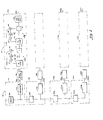
- a sonar system 10 is shown to include a transmitter element 12 here a projector which may be any suitable underwater acoustic transmitting type of element such as a flextensional transducer and so forth.
- Transducer 12 is fed a signal from a signal source 14 which provides a frequency modulated, wideband signal (i.e. generally greater than two octaves).
- Signal source 14, as well as other elements of the sonar, are controlled via system controller 20 or other suitable control along control paths 20a-20f as would be known to one of ordinary skill in the art.
- a signal is thus provided from system controller via line 20a to the signal source 14 to provide a suitably modulated transmit signal to be transmitted via projector 12.
- projector 12 produces acoustic energy in the medium here water, with the acoustic energy having the spectrum provided by the transmitted signal.
- This acoustic signal propagates in all directions or selective directions.
- the acoustic signal encounters an object such as a target, sea floor (cluttered) or large fish, etc. the acoustic energy bounces off of the object and portions of such energy are intercepted by a hydrophone or bank of hydrophones 22.
- a signal along line 20b is provided from system controller 20 to enable hydrophone 22 to respond to echoed or returned acoustic signals produced as a result of the reflection of the transmitted energy. Echo signals (not shown) are thus received by hydrophone 22 which here is responsive to energy having frequencies over a relatively wideband such as two octaves or greater and preferably due to the relative broadband characteristics thereof is a polymer type of hydrophone as is known in the art.
- Hydrophone 22 converts received acoustic energy into electrical signals. Such signals are fed through an amplifier or other preconditioning circuits (not shown) and then fed to an analog-to-digital converter 24.
- signal preconditioning circuits such as low noise amplifiers and buffer amplifiers are relatively wideband amplifiers and are further characterized as having relatively low levels of phase dispersion over t he bandwidth of the amplifier. That is, the amplifiers impart to their amplified output signal a substantially equal phase shift to the amplified output signals therefrom at least over the bandwidth of the transmitted signal.
- the sampling rate of the A/D converter is greater than twice the Nyquist sampling frequency (i.e. greater than twice the frequency of the highest frequency component signal in the input spectrum).
- the input signal is oversampled and thus the sampling rate is at two and a half to three times the highest input frequency.
- Analog-to-digital converter 24 converts the signals provided from hydrophone 22 in accordance with the sampling rate fed along line 20c into a stream of digital words. At the output of analog-to-digital converter 24 such stream of digital words are stored in a buffer memory 26 also under control of system controller 20 via signals on lines 20d. After a sufficient amount of data has been collected in memory 26, the data are fed to receiver processor21 which here includes a filter bank 30.
- Filter bank 30 is comprised of a plurality of bandpass filters (not shown) with each one of said bandpass filters having an asymmetric frequency response characteristic. In particular, the frequency response characteristic of each of the filters is selected to enhance processing of coherent components of the signal.
- the filter response is characterized as having a relatively sharp roll off or skirt at the high frequency side of the passband of the filter.
- the filter response of the filters is here much greater than 6 dB per octave.
- the frequency response is better than 200 dB/octave.
- a relatively shallow roll off or "skirt" characteristic is provided at the low frequency side of the passband.
- the characteristic of the low frequency side is not particularly important. Since the low frequency side of each of the bandpass filters is relatively not steep or sharp the passband characteristic is asymmetric.
- the signals from filter bank 30 are provided at outputs 30a-30hh.
- filter bank 30 here includes thirty-four individual bandpass filters although any number of filters greater than two could alternatively be used.
- Each of output lines 30a-30hh are fed to a corresponding one of a plurality of nonlinear range compressors 40a-40hh with here said range compressors being referred generally to range compressor bank 40.
- Each of the range compressors 40a-40hh includes a pair of cascaded, automatic gain control circuits 42a', 42a"-42hh', 42hh” having short and long adaptation rates and a half wave rectifier 49a-49hh coupled to a last one 42a", 42hh" of the "AGC" circuits 42a', 42a"-42hh', 42hh".
- the half wave rectifier uses a hyperbolic tangent mapping algorithm to assign values of the input signal from t he AGC stages to certain values of TANH for selective delays and saturation levels, as will be discussed in conjunction with FIG 2C.
- the non-linear range compressor 40 is used to obtain an estimate of the background noise and normalize the input data fed to it by the estimate of the background noise in the channel.
- the half wave rectifier portion 49a-49hh of the compressor 40 is used to provide a steep transition between background signal level of the data after scaling coherent components of the echo signal.
- the dynamic non-linear range compressed signals at outputs 40a'-40hh' of the bank 40 are fed to a coincident detector 50.
- the coincident detector 50 combines each of the detected signals from each of the signal banks.
- the detector 50 sums or integrates the returns in each channel to reinforce coherent components of the signal from each of the filter banks and sums the integrated returns in each channel across each of the channels of the filter to provide a sum of the coherent components of the received signal as will be described. Given a sufficiently large number of filters in the filter bank 30 such that there is only one coherent component per channel, the coincident detector 50 would integrate coherent components only across all of the channels.
- the output of the coincident 50 is fed to a user device 60 such as a display or signal processor for further action such as target identification.
- a user device 60 such as a display or signal processor for further action such as target identification.
- system controller 20 which provides appropriate control signals in a proper sequence to permit complete processing of data from the hydrophone 22 through user device 60.
- the hyperbolically frequency spaced bandpass filter bank 30 is shown to include a plurality of fitter stages here 31a-31hh representing thirty-four of such filter stages although any number of plural stages may be used.
- Each of said filter channels 31 a-31 hh is shown to include a notch filter 32a-32hh, respectively, coupled to a resonator 34a-34hh.
- Notch filters 32a-32hh are successively coupled in series whereas resonators 34a-34hh are coupled between adjacent notch filters, as shown, with the output of the resonators providing outputs 30a-30hh of the filter network 30.
- filter channels 31a-31 hh are coupled to interpolators 36a-36hh and the outputs of interpolators 36a-36hh are coupled to corresponding nonlinear dynamic range compressors 40a-40hh, as will be described below.
- each of the bandpass channels 31a-31 hh is characterized as providing a relatively steep filter response or skirt at the high frequency end of the passband of the respective channel 31a-31hh.
- each bandpass filter 31a-31hh of the filter bank 30 here has a relatively shallow "roll off,” whereas at high frequencies the filter bank 30 has a relatively sharp roll off of preferably about 200 dB/octave or greater.
- Each of these filter banks are cascaded together and further each of the filter banks has a center or nominal resonant frequency. The resonant frequency of each of the channels is spaced in frequency, as will be described below.
- each filter channel has an asymmetric passband frequency characteristic which overlaps a passband of preceding one of the channels.
- the sharp high frequency roll-off response of each of the bandpass filters 31a-31 hh permits good frequency discrimination and further permits relatively good time resolution since the spaced bandpass filters are relatively wideband.
- each of the bandpass filters 31a-31hh are, as indicated above, comprised of a notch filter 32a-32hh cascaded with a resonator 34a-34hh.
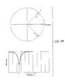
- Each one of the notch filters 32a-32hh have a filter transfer function which is characterized as having a complex zero (FIG. 2A) with a center frequency slightly higher than a corresponding center frequency of the associated resonator 34. Since the response of the complex zero filter exhibits a non-flat response at frequencies removed from the notch frequency, a complex pole is added (FIG.
- FIG. 2B This characteristic can be graphically depicted as shown in FIGs. 2A and 2B where the actual values of the zero root (R z ) and the pole root (Rp) are related to the location in frequency of the notch center frequency. Values of the pole root which are too close to the zero root can reduce the desired steep gradient characteristic of the filter. Ideally, values of these roots are obtained by computer simulation. Different values of Rp are chosen depending upon the resonant or center frequency of the filter response desired to be obtained.
- the transfer function of the notch filter can be expressed as:
- Each of the resonators 34a-34hh have a transfer function which may be expressed as where the coefficient A 1 represents the effective damping of the transfer function.
- a 1 2 ⁇ A 2 A 0 the roots of H(z) are equal and A 1 represents the critical value of damping.
- the damping ratio ⁇ is defined as the ratio of the effective damping to the critical value of damping.
- ⁇ is less than unity, the roots of Equation 2 are complex and the response is said to be underdamped.
- ⁇ takes on a value of 0.707 or less the frequency response of Equation 1 exhibits a peak at a frequency other than DC which is a feature which permits the simple configuration described in Equation 1 above to act as a bandpass filter.
- this filter arrangement when cascaded with a notch filter having a center or notch frequency slightly higher in frequency than the corresponding center frequency of the resonator, a filter exhibiting a relatively sharp gradient or roll off at the high frequency end of the filter is provided.
- each of the bandpass filters 31a-31 hh of the filter bank can be expressed as in Equation 3.
- the S term appearing in the numerator of the resonator is a scaling factor chosen so that the response of the bandpass filter is unity at the resonant or bandpass center frequency.
- the resonant frequencies are selected by dividing the amount of time required to hyperbolically frequency modulate the waveform to sweep over one octave.
- a transmitted signal could be used to sweep over an octave from 3818.18 hertz to 1909.9 hertz.
- This sweep is divided into n segments where n is the desired number of bandpass filters per octave here corresponding to eleven of such filter sections 30a-30hh per octave.
- the frequency of the hyperbolically frequency modulated waveform at each of the instances of time is used to determine the resonator frequencies.
- the resonators 34a-34h each have center frequencies located at frequencies corresponding to F1, F2, F3, ..., Fn, whereas the corresponding notches have center frequencies which are located at frequencies corresponding to F2, F3, F4, ..., Fn+1.
- F1 F2, F3, ..., Fn
- F2 F3, F4
- Fn+1 Fn+1.
- a resonator 34b has a center frequency at a frequency F2
- the corresponding notch filter 31 b has its notch frequency at the next higher resonator frequency F3.
- the individual bandpass filters are combined to provide a suitable filter bank 30 by serially cascading each of the notch filters 32a-32hh and providing taps or outputs between common adjacent filters for coupling to the corresponding resonators 34a-34hh, the last one of the notch filters 32hh feeding a signal to the corresponding last one of the resonators 34hh.
- the bandpass filters are arranged such that the bank is serial arranged from the highest notch frequency to the lowest notch frequency. That is, the first notch filter 32a has notch filter frequency disposed at the highest center frequency of the filter bank 30 with notch filter 32hh having a center frequency disposed at the lowest center frequency of the filter bank 30.
- a signal input from buffer memory 26 provides a plurality of outputs at the taps along the string of serially cascaded notch filters 32a-32hh. Furthermore, the signal as it is cascaded through each of the notches 32a-32hh has the higher frequency resonator signals attenuated as the signal passes through the notches into successively lower frequency notches.
- the bandpass filter bank 30 thus separates the input signal into a plurality of individual frequency components corresponding to components of the transmitted signal. This permits easier detection of the frequency components in the received signal.
- the following analysis can be used to calculate the center frequencies of each of the filter channels 31 a-31 hh.
- n samples at a sampling frequency f 3 are provided.
- the number of integer samples n can be increased arbitrarily by some factor M to provide a higher number of samples in each filter channel thus the number of samples can be Mn or Mn samples at f 3 .
- Mn or Mn samples at f 3 By increasing the number of samples by 100 effectively, the sampling rate of the A/D converter has been increased. The time taken to sweep one octave is therefore Mn/f 3 .
- the hyperbolically spaced resonant frequencies f occur at a time t having expanded samples Mn.
- the output signals from each of the channels should be in phase. This may be provided by calculating the filter phase response at the resonant or center frequency and correcting the filter outputs by removing entirely the effects of phase.
- One technique for correcting for phase may be provided by collecting samples of output data, reversing the order in time of the samples, and refiltering the data.
- the filter is designed to exhibit one half of the desired response.
- Asecond technique to calculate the filter response is to subtract the arc tangent of the denominator from the arc tangent of the numerator of the particular transfer function. Since the particular implementation used to provide the filter bank, i.e. the lowest order passband is cascaded through 33 stages, the filter coefficients are less than one. The cascading generates extremely low filter values or filter coefficients which may reduce the accuracy of the above arc tangent technique of correcting for phase response.
- a third technique to calculate phase correction is used.
- a sine and cosine sequence at a selected resonant or center frequency are provided and passed through the filters.
- the inputs are used to form an equation of the form where the output stage of the filter is used to provide equation with ⁇ M being the unknown phase shift of filter stage M.
- the sequences X M and Y M are multiplied resulting in a phase only sequence of eO m .
- Arc tangents are calculated for each point in the sequence and the average value of arc tangent is provided.
- Phase correction can occur either within the filters or in processing occurring after the processing shown in FIG. 2. The latter technique is here preferred.
- the filtered signals from bank 30 are fed to respective interpolators 36a-36hh.
- Each interpolator 34a-34hh provides phase correction to filtered channels to align the channels in phase and provides a sinusoidal interpolation of the filter data for sample rate enhancement.
- the interpolation algorithm implemented in the interpolators 36a-36h for a given channel M is given below. where A 2 is given by: and A 1 is given by:
- the interpolated data from interpolators 36a-36hh are fed to one of a plurality of nonlinear dynamic range compression circuits 40a-40hh of the dynamic range compression block 40.
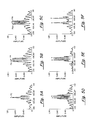
- Each of the individual circuits 40a-40hh includes a cascade of two automatic gain control circuits here 42a', 42a" shown for stage 40a cascaded with a half wave rectifier circuit 49a.
- the circuits 40a-40hh are here substantially identical but for differences in input frequencies and further that the first gain control circuit, eg 42a', implements short adaptation rates and rates and second gain control circuit, eg 42a", implements long adaptation rates.
- bank 40a includes a first stage 42a' and a second stage 42a".
- Stage 42a' includes a buffer memory 410 which provides a buffer or delay of m 1 samples of data
- the delayed data is fed to a divider 43 and undelayed data is fed to a first summer 44 which provides a sum of samples of said data. If the number of samples of said data summed is less than the number of samples M 1 then the average value of the data X n is given by Equation 7 below. That is, X n is divided in divider 43 by THR1.
- THR1 is an average period of time of a short duration over which the data X n is averaged to obtain an estimate of the background noise in X n at a short adaptation rate.
- AGC 42a" includes a buffer 411, summer 44', 46', multiplier 45', and divider 43' similar to that described above for AGC circuit 42a'.
- the filtered outputs 30a-30hh the bank are each scaled by the average value of the data over short (THR1) and long (THR2) adaptation rates.
- Each of said scaled channel signals from the AGC circuit it is fed a half wave rectifier 49a-49hh respectively as mentioned above.
- the algorithm is illustrated graphically in Fig. 2C.
- the x-axis values represent an input level to the rectifier with the y-axis values representing the corresponding output level from the rectifier.
- a saturation level of 10 and a delay value of 1.27 was used.
- a coincident detector 50 is shown fed by each of the channels of the outputs 40a'-40hh' of the nonlinear compression circuits 40a-40hh.
- the coincident detector circuit 50 is shown to include a plurality of channels 50a-50hh corresponding to the number of channels provided in filter bank 30, here 34 channels.
- coincident detector 50 is shown to include a first memory or buffer device 52a having an input and an output with the input being fed signals provided from the output of the half wave rectifier 49a of channel 40a via a line 41a and with the output being fed to a summer 53a.
- Summer 53a is disposed in a loop with a delay element 54a (i.e. a register or memory).
- Delay element 54a provides a delay corresponding to the number of samples per cycle.
- Channel 50a is thus used to integrate the corresponding coherent components of the signals fed to channel 50a. Since the location in time of the coherent components of the signal filtered through bank 30 is known as a result of the hyperbolically frequency modulated transmitted pulse, these coherent signal components can be integrated within each channel to reinforce the coherent components of the signals in each of said channels 50a-50hh. Thus in memories 56a-56hh are provided signals representing the integrated coherent components of signals in the respective channels 50a-50hh.
- the integration of the signals within said channels reinforces coherent components of signals within said channels.
- the outputs of memories 56a-56hh are fed to corresponding ones of second delay elements 57a-57hh, as shown.
- delay elements 57a-57hh each provide a delay corresponding to the channel to channel delay.
- each of the remaining channels 50b-50hh have a similar arrangement of elements, as shown illustratively for channel 50hh, and which correspondingly provide integrated coherent components of the signals fed from the respective non-linear range compression circuits 40b-40hh.
- the outputs of said buffer memories 56b-56hh are each fed to a respective one of a remaining plurality of delay elements 57b-57hh to delay the signals in accordance with the required channel to channel delay which is related to the temporal spacing of the portions of the transmitted waveform as tabulated in Table II.
- the outputs of the delays 57a-57hh are fed to a summer 59 to provide a coincident, coherent output signal which is fed to a user device 60 as shown in FIG.
- the summer 59 adds in phase the coherent components of the signals from each of the banks 50a-50hh. That is, the summer 59 integrates the signals across each of the channels 50a-50hh.
- the coincident detector 50 integrates the coherent components from each of the bandpass filters within each of the channels 50a-50hh and further integrates the coherent components of such signals across the channels 50a-50hh within summer 59.
- the delay elements 57a-57hh have a selected delay in accordance with the required channel to channel delay mentioned above to permit the signals in each channel to be integrated in phase and thus provide a composite output signal.
- an algorithm 50' to implement coincident detection is shown to include a first step 61 in which indices ICOMP, NCHN, K, and NPTS are all initialized.
- ICOMP is initialized to zero and corresponds to the channel to channel delay;
- NCHN is initialized to the number of channels in the filter here 34;
- K is initialized to one; and
- NPTS is initialized to the number of data points within each channel here corresponding to 3000 points per channel.
- the value of the index K is tested at decision 62 to see if it is equal to NCHN, the number of channels. Tf K is not equal to NCHN, control is transferred to a second initialization sequence 66.
- variable SMPCYC is set to the number of samples per cycle
- NCYC is set to the number of cycles for each segment of the transmitted waveform
- NSAMP is set to the number of samples for all cycles
- I is set equal to one.
- Control is transferred to a second testing step 68 in which the value of I is tested to determine if I is equal to the number of points NPTS here equal to 3000. If I is not equal to the number of points, then control is transferred to a third initialization step 70 and variable "sum" is set equal to zero and a variable f is set equal to one. Thereafter, control is transferred to a third test step 72 to test the value of f to determine if f is equal to NCYC.
- the data is summed within each channel and across each channel.
- the algorithm could be constructed to integrate the signal within each channel and then integrate the signals across the channels.
- step 74 control is returned to step 72 in which the value of f is again tested. As indicated in step 74, the value of f is incremented by one each time step 74 is executed.
- step 72 When the value of f equals NCYC, control is transferred from step 72 to step 76. Until f equals NCYC, however, control is transferred back to step 74. At step 76, the calculated SUM is stored in an array called SUM DATA and index I is incremented by 1. Control is then transferred back to step 68 and the value of I is tested to see if I equals the total number of points. It I equals the total number of points NPTS, then control is transferred from step 68 to step 78, otherwise control is transferred back to step 70.
- SUM DATA array now contains data corresponding to the original 34 channels of data compressed within each channel and across all of said channels. That is, it is seen that the coincidence detection algorithm 50' has three nested loops with index f being incremented a plurality of times for each time index I is incremented and index I being incremented a plurality of times for each time index K is incremented.
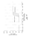
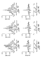
- plots of amplitude vs. delay in milliseconds are shown for processed echo information from a simulated target using a simulated transmitted waveform having a frequency bandwidth of two octaves (1909.09 to 477.25) and having the frequencies, the number of cycles at each frequency, and the number of samples in each cycle as set forth in Table II.
- This particular set of characteristics is illustrative only and other sets of parameters for a transmitted signal could, of course, be used and constructed in accordance with the techniques mentioned in conjunction with Table II.
- matched filter processing is employed to process the signal returns.
- the arrows over the peaks or highlights correspond to the locations where the processed highlight should detect a feature of an object.
- FIGs. 5A-5C are provided by a pair of echo returns which are separated by a predetermined number of samples (i.e. separated in time to ascertain the efficiency of the processing technique to detect features of an object separated by a minimum distance as represented by a delay of i samples). This gives an indication of the resolution capability of the technique to resolve minimal features of a target.
- the processed return indicates there are three peaks within the delay range of 103.33 to 106.67 milliseconds. Only two peaks should be observed thus one of the highlights is a false indication (or sideband) and furthermore the correct highlight as shown by arrow 73 is not present in the detected sample.
- four highlights are observed within the delay range of 103.33 to 106.67 milliseconds. Again, only two highlights should be observed.
- the highlights with the arrows disposed thereover correspond to the correct highlights.
- their amplitude is lower than the amplitude of sidelobes 75a, 75b, thus also indicating poor resolving characteristics for match filtering technique having five sample separation.
- the six sample delay processed by matched filtering techniques processes the returns correctly to provide the highlight indicated by the arrows at the proper positions.
- an additional highlight is provided within the pair of correct peaks and is not until a twenty sample separation that the correct highlights are provided with low sidelobes. Accordingly, the match filtering technique operating on the data described above is apparently capable of resolving, without ambiguities, the data having at least a twenty sample separation.
- the technique described above is also unable to resolve differences between the returns.
- the technique described above is able to resolve differences in returns as illustrated by the two highlights with the arrows disposed thereover although sidelobes, as well as the amplitude level between the peaks are relatively high.
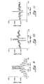
- a pair of echo returns are processed using conventional match filtering technique to provide the response as shown in FIGs. 7A-7C.
- the first return has a first characteristic
- the second return has the first characteristic but with a relative amplitude of 1, 0.7, and 0.5 of the first return for FIGs. 7A-7C, respectively.
- the second return is spaced from the first return by six samples.
- the first return is barely able to resolve the differences between the two signals.
- the correct highlights are denoted by the arrows disposed thereover. Since the sidelobes adjacent the correct highlights are higher than the correct highlights there is an ambiguity as to where the target is located.
- the relative amplitude of 0.7 as illustrated by the processed data in FIG. 7B shows that the second highlight is substantially below the sidelobes having a relative amplitude of about 0.4 as illustrated by the second arrow in FIG. 7B.
- FIG. 7C shows that the second highlight is virtually eliminated.
- FIGs. 8A-8C corresponding returns processed using the techniques in accordance with the present invention are illustrated.
- the technique is able to resolve relative amplitudes of 1 and 0.7 as illustrated in FIGs. 8Aand 8B.
- the highlight is present although it is somewhat lower than one of the adjacent sidelobes although the adjacent sidelobe is spaced at approximately 20 milliseconds furtherfrom the anticipated second peak.
- FIGs. 7A-7C and 8A-8C are used to illustrate partially the effects of frequency attenuation on signal returns and show that for the technique, in accordance with the present invention, the processing is less sensitive to these attenuation effects than the conventional matched filtering approach.
- the match filtering technique the return which should be indicated by highlights appearing at the arrows indicates that the target extent is distorted in that the match filtering technique cannot resolve either the three sample separation or the six sample separation.
- the sidelobes appear as highlights adjacent the returns and confuse the extent of the target.
- the extent of the target is clearly recognized by the two highlights appearing by the illustrated arrows.
- the three sample separation of the second highlight is not evident in the processed return of FIG. 10, clearly the extent of the target representing the six sample separation, as pointed out by the two arrows is evident and thus the extent of the target can be ascertained in the multi-highlight environment.
- the target is detected as illustrated by a single highlight having a signal to noise ratio as low as -5.0 dB. This is in agreement with achievable performance based on the time-bandwidth product of the transmitted waveform.
- the processing technique described above includes multi-channel processing which breaks up a return or echo signal into locally compact wavelets in the time frequency domain. These wavelets when added in phase result in significant enhancement and estimation of target parameters since the wavelets being added in phase permit reinforcement of coherent components of the signals being reflected from a potential target.
- the above approach can be implemented using especially designed digital signal processors or using software algorithms. In either event, either the digital processors or the software would implement the algorithms and the processors illustrated and described above. Further, although the processing has been illustrated using two octaves, obviously a higher number of octaves would be more beneficial to improve detection and recognition capabilities. However, the processing technique could also be provided using a single octave although with fewer advantages over the conventional match filtering technique.
- the technique has been particularly described in conjunction with sonar processing of acoustic signals, the technique is also applicable to processing of communication signals, as well as radar signals.
- the key elements of the technique is the transmission of wideband waveforms in conjunction with multi-channel processing and coincident detection of coherent components for the returned or received signal in each of the channels for the receiver.
Landscapes
- Engineering & Computer Science (AREA)
- Computer Networks & Wireless Communication (AREA)
- Physics & Mathematics (AREA)
- General Physics & Mathematics (AREA)
- Radar, Positioning & Navigation (AREA)
- Remote Sensing (AREA)
- Measurement Of Velocity Or Position Using Acoustic Or Ultrasonic Waves (AREA)
Applications Claiming Priority (2)
| Application Number | Priority Date | Filing Date | Title |
|---|---|---|---|
| US815657 | 1991-12-31 | ||
| US07/815,657 US5179542A (en) | 1991-12-31 | 1991-12-31 | Signal processor |
Publications (3)
| Publication Number | Publication Date |
|---|---|
| EP0557660A2 true EP0557660A2 (de) | 1993-09-01 |
| EP0557660A3 EP0557660A3 (en) | 1994-11-23 |
| EP0557660B1 EP0557660B1 (de) | 1999-09-29 |
Family
ID=25218430
Family Applications (1)
| Application Number | Title | Priority Date | Filing Date |
|---|---|---|---|
| EP92311849A Expired - Lifetime EP0557660B1 (de) | 1991-12-31 | 1992-12-30 | Signalprozessor |
Country Status (3)
| Country | Link |
|---|---|
| US (1) | US5179542A (de) |
| EP (1) | EP0557660B1 (de) |
| DE (1) | DE69230064T2 (de) |
Cited By (2)
| Publication number | Priority date | Publication date | Assignee | Title |
|---|---|---|---|---|
| WO1998016846A1 (en) * | 1996-10-17 | 1998-04-23 | Celsiustech Electronics Ab | Procedure for the elimination of interference in a radar unit of the fmcw type |
| RU2453861C1 (ru) * | 2010-10-11 | 2012-06-20 | Российская Федерация, от имени которой выступает Министерство промышленности и торговли Российской Федерации (Минпромторг России) | Гидроакустический приемоизлучающий тракт |
Families Citing this family (24)
| Publication number | Priority date | Publication date | Assignee | Title |
|---|---|---|---|---|
| US5251185A (en) * | 1992-10-15 | 1993-10-05 | Raytheon Company | Sonar signal processor and display |
| US5367516A (en) * | 1993-03-17 | 1994-11-22 | Miller William J | Method and apparatus for signal transmission and reception |
| US5995539A (en) * | 1993-03-17 | 1999-11-30 | Miller; William J. | Method and apparatus for signal transmission and reception |
| US5451961A (en) * | 1993-11-08 | 1995-09-19 | Unisys Corporation | Time varying adaptive clutter filter and clutter residue sensor |
| US5602760A (en) * | 1994-02-02 | 1997-02-11 | Hughes Electronics | Image-based detection and tracking system and processing method employing clutter measurements and signal-to-clutter ratios |
| AU6938894A (en) * | 1994-03-03 | 1995-09-18 | Alexandr Sergeevich Dmitriev | Method of objects recognition |
| US5592171A (en) * | 1995-08-17 | 1997-01-07 | The United States Of America As Represented By The Secretary Of Commerce | Wind profiling radar |
| US5734577A (en) * | 1996-03-11 | 1998-03-31 | Lucent Technologies Inc. | Adaptive IIR multitone detector |
| US5781144A (en) * | 1996-07-03 | 1998-07-14 | Litton Applied Technology | Wide band video signal denoiser and method for denoising |
| US6141294A (en) * | 1999-03-10 | 2000-10-31 | The United States Of America As Represented By The Secretary Of The Navy | Data acquisition system including data transmission controller for octavely nested acoustic line arrays |
| US6711216B2 (en) * | 2001-06-28 | 2004-03-23 | Intel Corporation | Method and apparatus for an ultra-wideband radio utilizing MEMS filtering |
| US7173966B2 (en) * | 2001-08-31 | 2007-02-06 | Broadband Physics, Inc. | Compensation for non-linear distortion in a modem receiver |
| US6735264B2 (en) | 2001-08-31 | 2004-05-11 | Rainmaker Technologies, Inc. | Compensation for non-linear distortion in a modem receiver |
| US6867728B1 (en) | 2003-11-06 | 2005-03-15 | Lockheed Martin Corporation | Methods and systems for identifying signals-of-interest |
| US7624211B2 (en) * | 2007-06-27 | 2009-11-24 | Micron Technology, Inc. | Method for bus width negotiation of data storage devices |
| GB0717031D0 (en) | 2007-08-31 | 2007-10-10 | Raymarine Uk Ltd | Digital radar or sonar apparatus |
| EP3318885B1 (de) * | 2016-11-03 | 2019-08-21 | Alcatel-Lucent Shanghai Bell Co., Ltd. | Verfahren zur bestimmung eines abstands zu einer passiven intermodulationsquelle, vorrichtung und computerprogrammprodukt |
| CN111007505A (zh) * | 2019-11-08 | 2020-04-14 | 北京空间飞行器总体设计部 | 一种基于零陷估计的距离通道相位偏差估计方法及系统 |
| US11686839B1 (en) | 2020-02-18 | 2023-06-27 | HG Partners, LLC | Continuous-wave radar system for detecting ferrous and non-ferrous metals in saltwater environments |
| US11960000B2 (en) | 2020-02-18 | 2024-04-16 | HG Partners, LLC | Continuous-wave radar system for detecting ferrous and non-ferrous metals in saltwater environments |
| US11150341B2 (en) | 2020-02-18 | 2021-10-19 | HG Partners, LLC | Continuous-wave radar system for detecting ferrous and non-ferrous metals in saltwater environments |
| US12210092B1 (en) | 2020-02-18 | 2025-01-28 | HG Partners, LLC | Continuous-wave radar system for detecting ferrous and non-ferrous metals in saltwater environments |
| CN111487607B (zh) * | 2020-05-29 | 2021-11-12 | 南京信息工程大学 | 一种水下声紧缩场测试系统及方法 |
| GB2606159B (en) * | 2021-04-26 | 2024-10-23 | Wavefront Systems Ltd | Method of pre-processing acoustic signals received from an ensonified region of an underwater environment |
Family Cites Families (3)
| Publication number | Priority date | Publication date | Assignee | Title |
|---|---|---|---|---|
| US4047172A (en) * | 1972-05-30 | 1977-09-06 | General Electric Company | Signal processor for pulse-echo system providing interference level compensation and feed-forward normalization |
| US3988679A (en) * | 1973-05-04 | 1976-10-26 | General Electric Company | Wideband receiving system including multi-channel filter for eliminating narrowband interference |
| US4622552A (en) * | 1984-01-31 | 1986-11-11 | The United States Of America As Represented By The Secretary Of The Navy | Factored matched filter/FFT radar Doppler processor |
-
1991
- 1991-12-31 US US07/815,657 patent/US5179542A/en not_active Expired - Lifetime
-
1992
- 1992-12-30 DE DE69230064T patent/DE69230064T2/de not_active Expired - Lifetime
- 1992-12-30 EP EP92311849A patent/EP0557660B1/de not_active Expired - Lifetime
Cited By (3)
| Publication number | Priority date | Publication date | Assignee | Title |
|---|---|---|---|---|
| WO1998016846A1 (en) * | 1996-10-17 | 1998-04-23 | Celsiustech Electronics Ab | Procedure for the elimination of interference in a radar unit of the fmcw type |
| US6469662B2 (en) | 1996-10-17 | 2002-10-22 | Celsiustech Electronics Ab | Procedure for the elimination of interference in a radar unit of the FMCW type |
| RU2453861C1 (ru) * | 2010-10-11 | 2012-06-20 | Российская Федерация, от имени которой выступает Министерство промышленности и торговли Российской Федерации (Минпромторг России) | Гидроакустический приемоизлучающий тракт |
Also Published As
| Publication number | Publication date |
|---|---|
| DE69230064D1 (de) | 1999-11-04 |
| EP0557660A3 (en) | 1994-11-23 |
| EP0557660B1 (de) | 1999-09-29 |
| US5179542A (en) | 1993-01-12 |
| DE69230064T2 (de) | 2000-04-20 |
Similar Documents
| Publication | Publication Date | Title |
|---|---|---|
| US5179542A (en) | Signal processor | |
| US6043771A (en) | Compact, sensitive, low power device for broadband radar detection | |
| US5784026A (en) | Radar detection of accelerating airborne targets | |
| EP0149981A2 (de) | Anpassungsfähiger Radarsignalprozessor zur Entdeckung des nützlichen Echos und zur Unterdrückung der Störungen | |
| US8121222B2 (en) | Systems and methods for construction of time-frequency surfaces and detection of signals | |
| Yu et al. | Estimating the delay-Doppler of target echo in a high clutter underwater environment using wideband linear chirp signals: Evaluation of performance with experimental data | |
| US5235338A (en) | Moving target detection through range cell migration radar | |
| Atkins et al. | Transmit-signal design and processing strategies for sonar target phase measurement | |
| US5949739A (en) | Sonar bearing estimation of extended targets | |
| US5251186A (en) | Preprocessor and adaptive beamformer for linear-frequency modulation active signals | |
| EP1528407A1 (de) | Zerlegung eines breitbandigen Zufallssignals | |
| US5212490A (en) | Echo ranging system for detecting velocity and range of targets using composite doppler invariant-like transmissions with suppression of false targets | |
| Altesmber et al. | Doppler-tolerant classification of distributed targets--a bionic sonar | |
| AU664802B2 (en) | Echo ranging system | |
| US5790475A (en) | Process and apparatus for improved interference suppression in echo-location and imaging systems | |
| Ashry et al. | Comparative analysis between SAR pulse compression techniques | |
| US3795912A (en) | Spectrum analysis radar system | |
| CN114374407B (zh) | 基于m序列的空间信道特性预测方法、系统及可存储介质 | |
| JP3727765B2 (ja) | 受信装置 | |
| KR20150058682A (ko) | 표적 속도에 따른 도플러 효과를 보상하는 고속 lfm 표적 검출 방법 및 장치 | |
| UA30234U (uk) | Система ближнього гідроакустичного безперервного моніторингу підводної обстановки територіальних вод морських акваторій | |
| Jonsson | Direct signal interference suppression and target detection for low-cost SDR-based passive bistatic radar | |
| RU202191U1 (ru) | Радиоприемное устройство импульсно-доплеровской РЛС с многообзорным накоплением сигнала | |
| JPH02676B2 (de) | ||
| RU2249833C2 (ru) | Способ обнаружения сигналов |
Legal Events
| Date | Code | Title | Description |
|---|---|---|---|
| PUAI | Public reference made under article 153(3) epc to a published international application that has entered the european phase |
Free format text: ORIGINAL CODE: 0009012 |
|
| AK | Designated contracting states |
Kind code of ref document: A2 Designated state(s): DE FR GB |
|
| PUAL | Search report despatched |
Free format text: ORIGINAL CODE: 0009013 |
|
| AK | Designated contracting states |
Kind code of ref document: A3 Designated state(s): DE FR GB |
|
| 17P | Request for examination filed |
Effective date: 19950502 |
|
| 17Q | First examination report despatched |
Effective date: 19970616 |
|
| GRAG | Despatch of communication of intention to grant |
Free format text: ORIGINAL CODE: EPIDOS AGRA |
|
| GRAG | Despatch of communication of intention to grant |
Free format text: ORIGINAL CODE: EPIDOS AGRA |
|
| GRAG | Despatch of communication of intention to grant |
Free format text: ORIGINAL CODE: EPIDOS AGRA |
|
| GRAH | Despatch of communication of intention to grant a patent |
Free format text: ORIGINAL CODE: EPIDOS IGRA |
|
| GRAH | Despatch of communication of intention to grant a patent |
Free format text: ORIGINAL CODE: EPIDOS IGRA |
|
| GRAA | (expected) grant |
Free format text: ORIGINAL CODE: 0009210 |
|
| AK | Designated contracting states |
Kind code of ref document: B1 Designated state(s): DE FR GB |
|
| REF | Corresponds to: |
Ref document number: 69230064 Country of ref document: DE Date of ref document: 19991104 |
|
| ET | Fr: translation filed | ||
| PLBE | No opposition filed within time limit |
Free format text: ORIGINAL CODE: 0009261 |
|
| STAA | Information on the status of an ep patent application or granted ep patent |
Free format text: STATUS: NO OPPOSITION FILED WITHIN TIME LIMIT |
|
| 26N | No opposition filed | ||
| REG | Reference to a national code |
Ref country code: GB Ref legal event code: IF02 |
|
| PGFP | Annual fee paid to national office [announced via postgrant information from national office to epo] |
Ref country code: GB Payment date: 20101229 Year of fee payment: 19 |
|
| PGFP | Annual fee paid to national office [announced via postgrant information from national office to epo] |
Ref country code: FR Payment date: 20111219 Year of fee payment: 20 |
|
| PGFP | Annual fee paid to national office [announced via postgrant information from national office to epo] |
Ref country code: DE Payment date: 20111229 Year of fee payment: 20 |
|
| REG | Reference to a national code |
Ref country code: DE Ref legal event code: R071 Ref document number: 69230064 Country of ref document: DE |
|
| REG | Reference to a national code |
Ref country code: DE Ref legal event code: R071 Ref document number: 69230064 Country of ref document: DE |
|
| REG | Reference to a national code |
Ref country code: GB Ref legal event code: PE20 Expiry date: 20121229 |
|
| PG25 | Lapsed in a contracting state [announced via postgrant information from national office to epo] |
Ref country code: GB Free format text: LAPSE BECAUSE OF EXPIRATION OF PROTECTION Effective date: 20121229 |
|
| PG25 | Lapsed in a contracting state [announced via postgrant information from national office to epo] |
Ref country code: DE Free format text: LAPSE BECAUSE OF EXPIRATION OF PROTECTION Effective date: 20130101 |