EP0557672B1 - Vorrichtung zum kontinuierlichen Behandeln durch die Wirkung von Flüssigkeiten von in Masse angelieferten kleinen Gegenständen - Google Patents
Vorrichtung zum kontinuierlichen Behandeln durch die Wirkung von Flüssigkeiten von in Masse angelieferten kleinen Gegenständen Download PDFInfo
- Publication number
- EP0557672B1 EP0557672B1 EP92830075A EP92830075A EP0557672B1 EP 0557672 B1 EP0557672 B1 EP 0557672B1 EP 92830075 A EP92830075 A EP 92830075A EP 92830075 A EP92830075 A EP 92830075A EP 0557672 B1 EP0557672 B1 EP 0557672B1
- Authority
- EP
- European Patent Office
- Prior art keywords
- container
- objects
- liquids
- elements
- treated
- Prior art date
- Legal status (The legal status is an assumption and is not a legal conclusion. Google has not performed a legal analysis and makes no representation as to the accuracy of the status listed.)
- Expired - Lifetime
Links
Images
Classifications
-
- B—PERFORMING OPERATIONS; TRANSPORTING
- B05—SPRAYING OR ATOMISING IN GENERAL; APPLYING FLUENT MATERIALS TO SURFACES, IN GENERAL
- B05B—SPRAYING APPARATUS; ATOMISING APPARATUS; NOZZLES
- B05B13/00—Machines or plants for applying liquids or other fluent materials to surfaces of objects or other work by spraying, not covered by groups B05B1/00 - B05B11/00
- B05B13/02—Means for supporting work; Arrangement or mounting of spray heads; Adaptation or arrangement of means for feeding work
- B05B13/0221—Means for supporting work; Arrangement or mounting of spray heads; Adaptation or arrangement of means for feeding work characterised by the means for moving or conveying the objects or other work, e.g. conveyor belts
- B05B13/025—Means for supporting work; Arrangement or mounting of spray heads; Adaptation or arrangement of means for feeding work characterised by the means for moving or conveying the objects or other work, e.g. conveyor belts the objects or work being present in bulk
- B05B13/0257—Means for supporting work; Arrangement or mounting of spray heads; Adaptation or arrangement of means for feeding work characterised by the means for moving or conveying the objects or other work, e.g. conveyor belts the objects or work being present in bulk in a moving container, e.g. a rotatable foraminous drum
-
- B—PERFORMING OPERATIONS; TRANSPORTING
- B08—CLEANING
- B08B—CLEANING IN GENERAL; PREVENTION OF FOULING IN GENERAL
- B08B3/00—Cleaning by methods involving the use or presence of liquid or steam
- B08B3/04—Cleaning involving contact with liquid
- B08B3/041—Cleaning travelling work
- B08B3/042—Cleaning travelling work the loose articles or bulk material travelling gradually through a drum or other container, e.g. by helix or gravity
Definitions
- the aforespecified industrially produced objects are often manufactured making use of molding machines, as die-presses and rolling machines.
- Other objects are produced by automatic turning or by other machining operations which usually require the use of lubricating means.
- Still other pieces are treated in quenching baths, wherein oily substances are normally used as quenching means.
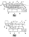
- a "washing" machine comprising (see fig. 1 of the accompanying drawings) a cylinder A of perforated plate, positioned horizontally - or slightly inclined in respect of the horizontal plane - and revolving about its axis, said cylinder housing helical vanes B forming a worm.
- the material in small pieces C to be treated, loaded in bulk in the dosing hopper D, is gradually poured into the lower part of the cylinder A, the rotation of which causes - thanks to the helical vanes B - the foward motion of said pieces (from left to right in the drawing), until they are finally discharged into E.
- Jets of treating liquid under pressure (consisting for instance - in the case of pieces covered in oil or grease - of one or more, normally alkaline-based, detergent solutions) are sprayed on the material to be treated, along its travelling path, through a set of nozzles G from a pipeline F inside the cylinder A.
- the liquid drops by gravity through the holes provided in the cylinder A, collecting into the underlying tanks H, L, M.
- the detergent solutions are generally at least partially recycled, after eventual purification and regeneration.
- Another problem of this machinery involves the treatment of delicate steel objects, which become fragile as they come out from the quenching baths after the hardening process; such objects, whose projections or grips can get stuck into the holes of the cylinder A, may easily break due to the weight of the overlying material.
- This machine has many of the inconveniences of the previous ones when its container is formed by only a drum, and it results expensive and not practical when the container is formed by more drums (which must have different diameters). Besides, also in it there is the necessity to mount the container inclined in respect of the horizontal plane.
- the present invention instead now finally solves this ancient and important problem in a brilliant way, by supplying a machine which can be used in a very wide range of applications, from the mechanical industry (where this requirement is particularly felt in various sectors and no doubt calls for an immediate use) to the agricultural and food industry, as well as in other different fields.
- the object is achieved with a machine for the continuous treatment by means of liquids of small objects fed in bulk, comprising a rotating container formed of a plurality of coaxial elements positioned tail-to-head, inclined vanes projecting from the inner walls of said elements for the mechanical advancement of the objects being treated, said elements being reciprocally connected with the interposition of gaps to discharge the treatment liquids, and fixed pipelines running along the inside of said container, provided with nozzles to spray the liquids onto said objects, characterized in that said tail-to-head coaxial elements consist of identical, frustoconical or frustopyramidal hollow bodies, all set with their minor base or tail in the feeding direction of the objects being treated and in that, the common axis of said elements corresponds to the rotation axis of the cotainer and it is an horizontal axis.
- the machine also comprises tanks to collect the treatment liquids in correspondence of the connection zones between the frustoconical elements of the container - and thus of the gaps formed in said zones for discharging said liquids - as well as means, at the outlet end of the container, to receive the treated objects; it can also provide for means to recycle and at least partly recover the treatment liquids, as well as the heat.
- Said machine can have the continuous or intermittent rotation of the container at adjustable speed and can moreover be housed into a vacuum chamber, equipped with smoke and steam filters or cleaners.
- the preferred embodiment of the machine according to the invention for the continuous treatment by means of liquids of small objects fed in bulk, comprises a horizontal rotating container 1 (fig. 2), formed of a plurality of hollow coaxial identical elements 2 of frustoconical or frustopyramidal shape, positioned tail-to-head and housing inclined vanes 3 which project from their inner walls so as to form a screw.
- the elements 2 (four in fig. 2) are all set in the same direction, so that wide gaps 4 are formed in correspondence of their connection zones.
- the uniform setting of the elements 2, the inclination of their inwardly projecting vanes 3, and the rotation sense of the container 1, are determined so that the bulk material introduced in said container can move forward from one end to the other end thereof, in the head-to-tail direction (i.e. starting from the major base towards the minor base of said elements 2).
- One or more fixed pipelines 5 run inside the container 1, substantially along its rotation axis and/or in proximity and parallel thereto, said pipelines 5 being provided with nozzles 6 to feed one or more treatment liquids into the various elements 2.
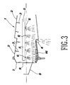
- the bases of the various elements 2 are open; nevertheless, the major inlet base, or head, of the first element 2 comprises a flange 7 (see fig. 4) which delimits an opening 8 - possibly screened by a baffle - through which is introduced a chute 9 to feed the objects 10 to be treated.
- Tanks 11, to collect the treatment liquids, are positioned under the container 1 in correspondence of the connection zones between the elements 2, and means 12 to collect the treated objects, consisting of a vessel (as shown) or of a conveyor, are positioned at the outlet of said container 1.
- the rotation of the container 1 can be continuous or intermittent, and of variable speed, according to the requirements of each single treatment, and it can be obtained and adjusted by conventional means.
- the small objects 10 to be treated are continuously fed from the chute 9 into the first element 2 of the rotating container 1, while the various treatment liquids are sprayed from the nozzles 6 of the pipeline 5 into the various elements 2.
- the objects move forward into the first element 2 (fig. 4) and are fed, from this latter, into the second element 2, and so forth, thanks to the mechanical action of the vanes 3. While moving forward the objects are thus progressively hit by the jets of the various liquids sprayed from the nozzles 6, and are hence subjected to the required treatments.
- the machine can be completed with at least partially automatic means for the recycle, percolation, re-titration and thermal conditioning of the treatment liquids, while it can be housed into a vacuum chamber equipped with filters and cleaners to prevent the spreading of smokes and harmful vapours, especially in work environments.
- the machine according to the invention can also be equipped with an immersion washing system (shown by 16 in fig. 4) to treat the objects in the first element 2 of the rotating container 1, just downstream of the inlet opening 8.
- an immersion washing system shown by 16 in fig. 4 to treat the objects in the first element 2 of the rotating container 1, just downstream of the inlet opening 8.
- the machine according to the invention could be realized in many other different ways.
- 2 means could be provided to recover the heat from the treatment liquids and/or solutions.
- the elements 2 of the rotating container 1, as well as the pipelines 5 and tanks 11 forming part of the machine can be of any number according to the requirements of the various treatments having to be carried out by said machine, thereby differing in number from those of the previously described in the specification and illustrated in the drawings.
Landscapes
- Apparatuses For Bulk Treatment Of Fruits And Vegetables And Apparatuses For Preparing Feeds (AREA)
- Cleaning By Liquid Or Steam (AREA)
- Nozzles (AREA)
Claims (9)
- Vorrichtung zur kontinuierlichen Behandlung von massenhaft zugeführten kleinen Gegenständen durch Flüssigkeiten, von der Art, die einen sich drehenden Behälter (1), der aus einer Mehrzahl von koaxialen, gegensinnig angeordneten Elementen gebildet ist, geneigten Flügeln (3), die von den Innenwandungen der Elemente (2) nach innen vorragen, um die zu behandelnden Gegenstände (10) mechanisch fortzubewegen, wobei die Elemente (2) gegenseitig unter Belassung von Spalten (4) , um die Behandlungsflüssigkeit abzulassen, miteinander verbunden sind, und mit ortsfesten Rohren (5), die entlang des Inneren des Behälters (1) laufen, die mit Düsen (6) versehen sind, um die Flüssigkeiten auf die Gegenstände (10) zu sprühen, besteht, dadurch gekennzeichnet, daß jedes der gegensinnig angeordneten koaxialen Elemente (2) aus zwei identischen, kegelstumpfförmigen oder aber pyramidenstumpfförmigen hohlen Körpern bestehen, die jeweils mit ihrer kleineren Basis oder ihrem kleineren Ende in der Förderrichtung der behandelten Gegenstände (10) angeordnet sind, und dadurch, daß die gemeinsame Achse der Elemente (2) der Drehachse des Behälters (1) entspricht und eine horizontale Achse ist.
- Vorrichtung nach Anspruch 1, weiter mit Tanks (11) zum Sammeln der Behandlungsflüssigkeiten in Übereinstimmung mit den Verbindungsbereichen zwischen den Elementen (2, 13) des Behälters (1) und derjenigen der Spalte (4, 14), die in den Zonen zum Ablassen der Flüssigkeiten ausgebildet sind, als auch mit Mitteln (12) an dem Auslaßende des Behälters (1) zur Aufnahme der behandelnden Gegenstände.
- Vorrichtung nach Anspruch 1 und 2, wobei Mittel vorgesehen sind, um sowohl die Behandlungsflüssigkeit als auch die Wärme zurückzuführen und wenigstens teilweise zurückzugewinnen.
- Vorrichtung nach einem der Ansprüche 1 - 3, wobei die Drehung des Behälters (1) kontinuierlich ist.
- Vorrichtung nach Anspruch 1 - 3, wobei die Drehung des Behälters (1) intermittierend ist.
- Vorrichtung einem der Ansprüche 1 - 5, wobei die Drehgeschwindigkeit des Behälters (1) einstellbar ist.
- Vorrichtung nach einem der Ansprüche 1 - 6, wobei wenigstens das erste der Elemente (2) des Behälters (1) Mittel für eine Tauchwaschung der behandelten Gegenstände aufweist.
- Vorrichtung nach einem der Ansprüche 1 - 7, wobei das erste Element (2) des Behälters (1) mit einem Leitblech zum Dosieren des Einlasses der behandelnden Gegenstände versehen ist.
- Vorrichtung nach einem der Ansprüche 1 - 8, eingebracht in eine Vakuumkammer, die mit Rauch- und Staubfiltern oder -reinigern ausgerüstet ist.
Priority Applications (3)
| Application Number | Priority Date | Filing Date | Title |
|---|---|---|---|
| EP92830075A EP0557672B1 (de) | 1992-02-24 | 1992-02-24 | Vorrichtung zum kontinuierlichen Behandeln durch die Wirkung von Flüssigkeiten von in Masse angelieferten kleinen Gegenständen |
| AT92830075T ATE115008T1 (de) | 1992-02-24 | 1992-02-24 | Vorrichtung zum kontinuierlichen behandeln durch die wirkung von flüssigkeiten von in masse angelieferten kleinen gegenständen. |
| DE69200835T DE69200835T2 (de) | 1992-02-24 | 1992-02-24 | Vorrichtung zum kontinuierlichen Behandeln durch die Wirkung von Flüssigkeiten von in Masse angelieferten kleinen Gegenständen. |
Applications Claiming Priority (1)
| Application Number | Priority Date | Filing Date | Title |
|---|---|---|---|
| EP92830075A EP0557672B1 (de) | 1992-02-24 | 1992-02-24 | Vorrichtung zum kontinuierlichen Behandeln durch die Wirkung von Flüssigkeiten von in Masse angelieferten kleinen Gegenständen |
Publications (2)
| Publication Number | Publication Date |
|---|---|
| EP0557672A1 EP0557672A1 (de) | 1993-09-01 |
| EP0557672B1 true EP0557672B1 (de) | 1994-12-07 |
Family
ID=8212070
Family Applications (1)
| Application Number | Title | Priority Date | Filing Date |
|---|---|---|---|
| EP92830075A Expired - Lifetime EP0557672B1 (de) | 1992-02-24 | 1992-02-24 | Vorrichtung zum kontinuierlichen Behandeln durch die Wirkung von Flüssigkeiten von in Masse angelieferten kleinen Gegenständen |
Country Status (3)
| Country | Link |
|---|---|
| EP (1) | EP0557672B1 (de) |
| AT (1) | ATE115008T1 (de) |
| DE (1) | DE69200835T2 (de) |
Families Citing this family (2)
| Publication number | Priority date | Publication date | Assignee | Title |
|---|---|---|---|---|
| DE19518721A1 (de) * | 1995-05-24 | 1996-11-28 | Bohle L B Pharmatech Gmbh | Trommelcoater |
| CN109013124B (zh) * | 2018-08-17 | 2020-02-11 | 南通宝得利机械制造有限公司 | 一种管道内壁喷涂装置 |
Family Cites Families (4)
| Publication number | Priority date | Publication date | Assignee | Title |
|---|---|---|---|---|
| US1383418A (en) * | 1921-07-05 | A corpora | ||
| GB1558566A (en) * | 1975-09-26 | 1980-01-03 | Wiggin & Co Ltd Henry | Apparatus for treating small articles with liquid |
| EP0093264A3 (de) * | 1982-04-30 | 1984-07-11 | Ransohoff Co. | Verfahren und Vorrichtung zum Reinigen von Metallteilchen |
| BE902802A (fr) * | 1985-07-03 | 1986-01-03 | Herstal Sa | Installation de nettoyage de produits en vrac. |
-
1992
- 1992-02-24 DE DE69200835T patent/DE69200835T2/de not_active Expired - Fee Related
- 1992-02-24 AT AT92830075T patent/ATE115008T1/de not_active IP Right Cessation
- 1992-02-24 EP EP92830075A patent/EP0557672B1/de not_active Expired - Lifetime
Also Published As
| Publication number | Publication date |
|---|---|
| EP0557672A1 (de) | 1993-09-01 |
| DE69200835T2 (de) | 1995-07-06 |
| ATE115008T1 (de) | 1994-12-15 |
| DE69200835D1 (de) | 1995-01-19 |
Similar Documents
| Publication | Publication Date | Title |
|---|---|---|
| EP0091566B1 (de) | Verfahren und Vorrichtung zur Nachkondensation von Polykondensaten | |
| EP0591299B1 (de) | Verfahren und vorrichtung zum entwässern von schlämmen | |
| US5245919A (en) | Apparatus for peeling fruits or vegetables | |
| EP3383552A1 (de) | Lackierkabine von overspraybeseitigungssystem, verfahren zur beseitigung von overspray und anlage | |
| US10773358B2 (en) | Part processing and cleaning apparatus and method of same | |
| DE4307789C3 (de) | Kontroll-Siebvorrichtung sowie Verwendung der Vorrichtung | |
| US2711557A (en) | Apparatus for handling sticky materials | |
| US5403395A (en) | Reel for applying topical substances to base products | |
| US2424803A (en) | Horizontal rotary abrading drum for peeling fruit and vegetables | |
| EP0557672A1 (de) | Vorrichtung zum kontinuierlichen Behandeln durch die Wirkung von Flüssigkeiten von in Masse angelieferten kleinen Gegenständen | |
| US4478171A (en) | Variably displaceable spray nozzles | |
| EP0528070A1 (de) | Verfahren und Einrichtung zum Aufbereiten von Schüttgütern | |
| US4453556A (en) | Spray treatment apparatus | |
| DE19750669C2 (de) | Waschanlage | |
| US4753046A (en) | Process for treatment by bulk agitation of rough castings or machined parts and machine for implementing the process | |
| US2290790A (en) | Method of distributing fluid in accurately measured quantities | |
| US3315589A (en) | Pellet forming apparatus | |
| CN222843813U (zh) | 一种高质量钢丸表面锈迹去除机 | |
| RU1796133C (ru) | Машина дл мойки плодов и овощей | |
| US20240238824A1 (en) | Painting plants with overspray removal systems | |
| SU289662A1 (ru) | Устройство для обработки материалов в тонком слое | |
| RU2228789C1 (ru) | Барабанный гранулятор | |
| SU844091A1 (ru) | Устройство дл очистки длинномерныхиздЕлий | |
| DE3621568A1 (de) | Reinigungs- und entfettungsanlage | |
| US4666482A (en) | Process for solidifying solvent refined coal |
Legal Events
| Date | Code | Title | Description |
|---|---|---|---|
| PUAI | Public reference made under article 153(3) epc to a published international application that has entered the european phase |
Free format text: ORIGINAL CODE: 0009012 |
|
| AK | Designated contracting states |
Kind code of ref document: A1 Designated state(s): AT BE CH DE DK ES FR GB GR IT LI LU MC NL PT SE |
|
| 17P | Request for examination filed |
Effective date: 19940128 |
|
| 17Q | First examination report despatched |
Effective date: 19940420 |
|
| 111L | Licence recorded |
Free format text: 0100 LOIRE THERMIE INDUSTRIELLE OU ELTI S.A. |
|
| GRAA | (expected) grant |
Free format text: ORIGINAL CODE: 0009210 |
|
| AK | Designated contracting states |
Kind code of ref document: B1 Designated state(s): AT BE CH DE DK ES FR GB GR IT LI LU MC NL PT SE |
|
| PG25 | Lapsed in a contracting state [announced via postgrant information from national office to epo] |
Ref country code: NL Effective date: 19941207 Ref country code: MC Free format text: LAPSE BECAUSE OF NON-PAYMENT OF DUE FEES Effective date: 19941207 Ref country code: GR Free format text: LAPSE BECAUSE OF FAILURE TO SUBMIT A TRANSLATION OF THE DESCRIPTION OR TO PAY THE FEE WITHIN THE PRESCRIBED TIME-LIMIT Effective date: 19941207 Ref country code: ES Free format text: THE PATENT HAS BEEN ANNULLED BY A DECISION OF A NATIONAL AUTHORITY Effective date: 19941207 Ref country code: DK Effective date: 19941207 Ref country code: BE Effective date: 19941207 Ref country code: AT Effective date: 19941207 |
|
| REF | Corresponds to: |
Ref document number: 115008 Country of ref document: AT Date of ref document: 19941215 Kind code of ref document: T |
|
| REG | Reference to a national code |
Ref country code: CH Ref legal event code: PLI Owner name: LOIRE THERMIE INDUSTRIELLE OU ELTI S.A. |
|
| REF | Corresponds to: |
Ref document number: 69200835 Country of ref document: DE Date of ref document: 19950119 |
|
| ITF | It: translation for a ep patent filed | ||
| PGFP | Annual fee paid to national office [announced via postgrant information from national office to epo] |
Ref country code: DE Payment date: 19950223 Year of fee payment: 4 |
|
| PGFP | Annual fee paid to national office [announced via postgrant information from national office to epo] |
Ref country code: CH Payment date: 19950227 Year of fee payment: 4 |
|
| PG25 | Lapsed in a contracting state [announced via postgrant information from national office to epo] |
Ref country code: LU Free format text: LAPSE BECAUSE OF NON-PAYMENT OF DUE FEES Effective date: 19950228 |
|
| PGFP | Annual fee paid to national office [announced via postgrant information from national office to epo] |
Ref country code: FR Payment date: 19950228 Year of fee payment: 4 |
|
| PG25 | Lapsed in a contracting state [announced via postgrant information from national office to epo] |
Ref country code: SE Effective date: 19950307 Ref country code: PT Effective date: 19950307 |
|
| ET | Fr: translation filed | ||
| NLV1 | Nl: lapsed or annulled due to failure to fulfill the requirements of art. 29p and 29m of the patents act | ||
| PLBE | No opposition filed within time limit |
Free format text: ORIGINAL CODE: 0009261 |
|
| 26N | No opposition filed | ||
| PG25 | Lapsed in a contracting state [announced via postgrant information from national office to epo] |
Ref country code: GB Effective date: 19960224 |
|
| PG25 | Lapsed in a contracting state [announced via postgrant information from national office to epo] |
Ref country code: LI Effective date: 19960229 Ref country code: CH Effective date: 19960229 |
|
| REG | Reference to a national code |
Ref country code: CH Ref legal event code: PL |
|
| GBPC | Gb: european patent ceased through non-payment of renewal fee |
Effective date: 19960224 |
|
| PG25 | Lapsed in a contracting state [announced via postgrant information from national office to epo] |
Ref country code: FR Effective date: 19961031 |
|
| PG25 | Lapsed in a contracting state [announced via postgrant information from national office to epo] |
Ref country code: DE Effective date: 19961101 |
|
| REG | Reference to a national code |
Ref country code: FR Ref legal event code: ST |
|
| PG25 | Lapsed in a contracting state [announced via postgrant information from national office to epo] |
Ref country code: IT Free format text: LAPSE BECAUSE OF NON-PAYMENT OF DUE FEES;WARNING: LAPSES OF ITALIAN PATENTS WITH EFFECTIVE DATE BEFORE 2007 MAY HAVE OCCURRED AT ANY TIME BEFORE 2007. THE CORRECT EFFECTIVE DATE MAY BE DIFFERENT FROM THE ONE RECORDED. Effective date: 20050224 |