EP0557751A2 - Obusier blindé comportant un bras de chargement pivotant et un magasin pour munitions du type à chaîne sans fin - Google Patents
Obusier blindé comportant un bras de chargement pivotant et un magasin pour munitions du type à chaîne sans fin Download PDFInfo
- Publication number
- EP0557751A2 EP0557751A2 EP93101705A EP93101705A EP0557751A2 EP 0557751 A2 EP0557751 A2 EP 0557751A2 EP 93101705 A EP93101705 A EP 93101705A EP 93101705 A EP93101705 A EP 93101705A EP 0557751 A2 EP0557751 A2 EP 0557751A2
- Authority
- EP
- European Patent Office
- Prior art keywords
- grenade
- magazine
- weapon
- grenades
- loading arm
- Prior art date
- Legal status (The legal status is an assumption and is not a legal conclusion. Google has not performed a legal analysis and makes no representation as to the accuracy of the status listed.)
- Granted
Links
- 238000012546 transfer Methods 0.000 claims abstract description 37
- 230000009471 action Effects 0.000 claims abstract description 6
- 239000003380 propellant Substances 0.000 claims description 11
- 238000010304 firing Methods 0.000 claims description 3
- 238000000034 method Methods 0.000 description 8
- 230000008569 process Effects 0.000 description 8
- 238000006073 displacement reaction Methods 0.000 description 2
- 239000002223 garnet Substances 0.000 description 2
- 238000013459 approach Methods 0.000 description 1
- 230000008901 benefit Effects 0.000 description 1
- 230000015572 biosynthetic process Effects 0.000 description 1
- 230000008859 change Effects 0.000 description 1
- 238000005516 engineering process Methods 0.000 description 1
- 230000007246 mechanism Effects 0.000 description 1
- 230000007935 neutral effect Effects 0.000 description 1
- 230000000284 resting effect Effects 0.000 description 1
- 238000013519 translation Methods 0.000 description 1
- 239000013585 weight reducing agent Substances 0.000 description 1
Images

Classifications
-
- F—MECHANICAL ENGINEERING; LIGHTING; HEATING; WEAPONS; BLASTING
- F41—WEAPONS
- F41A—FUNCTIONAL FEATURES OR DETAILS COMMON TO BOTH SMALLARMS AND ORDNANCE, e.g. CANNONS; MOUNTINGS FOR SMALLARMS OR ORDNANCE
- F41A9/00—Feeding or loading of ammunition; Magazines; Guiding means for the extracting of cartridges
- F41A9/01—Feeding of unbelted ammunition
- F41A9/06—Feeding of unbelted ammunition using cyclically moving conveyors, i.e. conveyors having ammunition pusher or carrier elements which are emptied or disengaged from the ammunition during the return stroke
- F41A9/09—Movable ammunition carriers or loading trays, e.g. for feeding from magazines
- F41A9/10—Movable ammunition carriers or loading trays, e.g. for feeding from magazines pivoting or swinging
- F41A9/13—Movable ammunition carriers or loading trays, e.g. for feeding from magazines pivoting or swinging in a vertical plane
- F41A9/16—Movable ammunition carriers or loading trays, e.g. for feeding from magazines pivoting or swinging in a vertical plane which is parallel to the barrel axis
-
- F—MECHANICAL ENGINEERING; LIGHTING; HEATING; WEAPONS; BLASTING
- F41—WEAPONS
- F41A—FUNCTIONAL FEATURES OR DETAILS COMMON TO BOTH SMALLARMS AND ORDNANCE, e.g. CANNONS; MOUNTINGS FOR SMALLARMS OR ORDNANCE
- F41A9/00—Feeding or loading of ammunition; Magazines; Guiding means for the extracting of cartridges
- F41A9/61—Magazines
- F41A9/64—Magazines for unbelted ammunition
- F41A9/76—Magazines having an endless-chain conveyor
Definitions
- the invention relates to a self-propelled howitzer with a weapon mounted on shield pegs in the turret of the tank, a circulation magazine arranged at the rear of the turret, in which the grenades are deposited essentially horizontally in the firing direction, and a device for transferring individual ones arranged between the magazine and the breech of the weapon Grenades from the magazine to the weapon and attached to the weapon storage, their elavation following device for attaching the grenade.
- the combat strength of a self-propelled howitzer depends largely on three factors. On the one hand, flexibility, i.e. the adaptability to different ammunition (length of the grenades, with or without propellant charge), the weapon cadence (rate of fire) and finally the amount of ammunition carried.
- the amount of ammunition carried is largely optimized in today's self-propelled howitzers through sophisticated magazine designs.
- Great flexibility with regard to the type of ammunition can also be achieved at least if the ammunition is fed to the weapon manually. Manual feeding, however, requires labor and physical effort and further limits the cadence of the weapon.
- Various attempts have therefore been made to transfer the ammunition from the magazine to the weapon in a more or less mechanized way by means of loading aids.
- the known loading aids are usually extremely complicated in terms of drive and functional technology and not very flexible.
- armored howitzers with a wedge lock and those with a rotary lock are known, which previously required a different ammunition feed.
- Other known systems make it necessary to move the weapon from the respective combat position (elevation) to the neutral position in order to be able to transfer and attach the ammunition. This is especially true when the magazine is housed in the rear of the tower and the grenades are oriented essentially horizontally in the firing direction. The cadence is reduced by moving the weapon out of the elevation and then relocating it into the elevation.
- the object of the invention is to propose an ammunition feed from the turret magazine to the weapon, which is characterized by great flexibility with regard to the type of ammunition and the type of weapon lock and also allows a high cadence and as a retrofit kit in existing howitzer howitzer can be installed.
- the transfer device has a loading arm, which is mounted on a shield pin and extends to the side of the weapon to the magazine and which delivers the grenade in the respective elevation of the weapon to the attachment device between an essentially horizontal take-over position in front of the magazine Transfer position is pivotable, the loading arm being locked in the transfer position, swiveling under the weight of the grenade into the transfer position against the force of a return spring after releasing the lock, and pivoting back into the transfer position after the grenade has been released to the attachment device under the action of the return spring.
- the loading arm thus bridges the transport path between the magazine and the bottom of the weapon or the weapon breech, which is provided by the free space, without the weapon itself having to leave its elevation.
- the loading arm In the take-over position in front of the magazine, the loading arm is locked in place. As a result, the loading arm assumes a defined take-over position, so that the grenade can be automatically transferred from the magazine to the loading arm without interference by means of a corresponding conveyor. Furthermore, in the locked position of the loading arm, the tank crew can tempt the grenade to be transferred in each case. After the locking mechanism has been released, the loading arm automatically swivels under the weight of the grenade it has picked up and against the force of the return spring into the transfer position, which corresponds to the elevation of the weapon. There the grenade is delivered to the attachment device. The associated weight reduction means that the loading arm swivels back into its take-over position under the action of the return spring, while at the same time the attachment device shifts and attaches the grenade into the core axis of the weapon.
- the loading arm can already take over the next grenade, so that a high cadence can be achieved despite the necessary displacement of the grenades from the horizontal position in the rear of the turret to the elevation position of the weapon.
- This type of ammunition feed is due to the weapon-proof approach Direction and the decoupling of the loading arm from this can be used both with twist locks and cross wedge locks, as well as for grenades of different lengths as far as ammunition is fired with propellant charge, the propellant charge is fed manually.
- the movement of the loading arm under the weight of the grenade and / or the return movement of the empty loading arm under the action of the return spring can optionally be supported and accelerated by a motor.
- the loading arm has at least one clamp gripping the grenade from the side on the circumference, the lower clamp legs of which serve as supports for the grenade in the take-over position and which can be pivoted about their common or a parallel axis, that the grenade automatically falls into a receptacle on the attachment device after the clamps have been opened in the transfer position.
- the formation of the clamps on the loading arm has the advantage that the grenade can be inserted at the transfer position by resting on the lower clamp leg between the only partially opened clamp legs and in the transfer position (weapon elevation) the transfer takes place solely by opening the clamps, so that the Grenade falls into the attachment device. No linear displacements of the grenade are necessary during the transfer. This also results in a quick transfer process. If necessary, several clamps can be arranged in alignment one behind the other or a single clamp with shell-like legs can be provided.
- the return spring engages the loading arm on the one hand and can be supported on the weapon or the attachment device on the other hand. It is preferably designed as a gas pressure spring.
- Conventional revolving magazines with horizontal grenades have as a means of conveyance a chain of bars guided in several loops with a front chain approximately at the level of the tops of the grenades, a rear chain and bars connecting both chains, and bottoms arranged between each loop, to which the bars are located between adjacent bars put on grenades.
- the known circulation magazines of this type are only suitable for the magazine of grenades of a certain length. As a result, the flexibility of the self-propelled howitzer suffers.
- stops are guided on the bars, which abut the bottom of the grenade and can be moved to align the tips of grenades of different lengths in order to align the front chain.
- Such a marching lashing can be formed in that a device for positioning the grenades is arranged on the front chain of the circulating magazine between the adjacent bars, said device having movable lashing members that can be placed on the top of the grenades, the lashing member, for example, having a fork that can be swung in and out is. The grenades are now firmly positioned between the rear stop and the lashing link.
- the front chain of a rod chain is aligned with the tips of the grenades, it hinders their transfer to the loading arm. It is therefore provided in a preferred embodiment of the invention that at least at the take-over position the front chain of the circulating magazine can be deflected from the alignment of the tips of the grenade to such an extent that the grenade in the take-over position can be transferred to the loading arm only by shifting in the direction of its axis .
- the grenade located in the take-over position in the magazine can be transferred to the loading arm without problems.
- the grenade only has to be pushed onto the loading arm in the direction of its axis.
- deflecting the chain allows access to the grenade tip in order to heat the grenade electrically or magnetically.
- the magazine can also be loaded with garnet from the inside of the tank.
- the floor between the loops of the chain of bars has a chute articulated in the area of the rear chain, which can be swiveled downwards to such an extent that the grenade can be passed under the front chain to the loading arm.
- the grenade in the transfer position is tilted down a little so that it can be moved below the chain onto the loading arm.
- the grenade can also be tempered in the same position.
- a thrust member engaging the bottom of the grenade and transferring it to the loading arm is arranged at the takeover position.
- the thrust link can be arranged, for example, at the rear end of a pull rod which extends forward, a telescope, a chain drive or the like.
- the attachment device is firmly attached to the weapon and thus follows its elevation.
- the attachment device has a receptacle for the grenade, which from the transfer position corresponding to the loading arm to the side of the weapon into a grenade in the soul axis of the weapon-bringing attachment position is movable.
- the grenade is thus transferred from the loading arm to the receptacle of the attachment, which is located on the side of the core axis and is attached to the weapon storage. Due to the lateral arrangement, the attachment device does not hinder the return of the weapon. On the other hand, the grenade can be easily moved into the soul axis of the weapon and moved from this position by moving the receptacle.
- an essentially identical circulation magazine for propellant charges is arranged behind the revolving magazine for the grenades, advantageously the revolving magazine for the propellant charges has a delivery position which is to the side or below one of the outer deflections of the revolving magazine for the grenades .
- the propellant charges can thus be removed from the magazine from the interior of the tank and fed into the weapon manually.
- Another embodiment is characterized in that the circulation magazine for the grenades and / or the circulation magazine for the propellant charges is attached to the rear of the tower as an interchangeable unit. In this way, the complete ammunition magazine can be manufactured as a retrofit kit and attached to the tower, so that time-consuming ammunition of the magazine is eliminated.
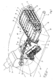
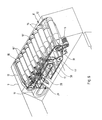
- the armored vehicle 1 shown in FIG. 1 has a howitzer 3 in a tower 2 with the weapon 4, which is mounted on horizontal shield pins 5 in the tower 2.
- the weapon 4 has a twist lock 6, which is shown in the open position in FIG. 1.
- the tower 2 has a rear end 7 which possibly extends beyond the vehicle contour and which accommodates a plurality of grenades 9, 10 of different lengths in a circulation magazine 8.
- the magazine has a front chain 11 and a rear chain 12 as conveying means, which is guided in several loops lying horizontally one above the other. A series of grenades is assigned to each loop.
- the magazine can be ammunitioned via a loading hatch 13 from the rear of the tower rear 7, as is indicated by the grenade 14 as an example.
- the magazine can also be ammunitioned from the interior of the tank, one of the strands of the front chain 11 having to be deflected, as described in connection with FIG. 6.
- the conveyor of the magazine is designed as a bar chain, in which the front chain 11 is connected to the rear chain 12 by means of bars 15 arranged equidistantly.
- the front chain 11 lies in each loop approximately in alignment with the grenade tips, while the rear chain 12 lies approximately in alignment with the center of the bottom of the grenades.
- the chain is driven by an electric motor 16.
- the loops are separated from one another by horizontal shelves, not shown, against which the grenades 9, 10 rest.
- the magazine has outer deflection shells 17 for guiding the grenades in the region of the apex of the loops.
- the distance between the chains 11, 12 is matched to the greatest length of garnet, so that the grenades 9 are positioned between the chains.
- stops 15 are slidably guided on the rods 15, which attack the bottom of the grenades 10 and are adjustable so that their tip is also in the area of the front chain 11 .
- Centering stops (not shown) are located on the bars 15 in the region of the front chain 11. March lashing grips in the area of the top of the grenade conditions that can be shifted or swiveled in and out using a spindle element between two bars.
- a loading arm 19 is pivotally mounted on the shield pin 5 of the howitzer 3, which is in the starting position of the loading process in the position shown in FIG. 1 and is fixed in this position by means of a lock 20, for example on the tower roof.
- the loading arm 19 has three brackets 21 arranged one behind the other, which serve to receive the grenades 9, 10 from the magazine.
- An attachment device 22 is also attached to the weapon storage and has an upwardly open, shell-like receptacle 23 for a single grenade. The receptacle 23 can be pivoted about an axis, not shown, from the transfer position shown on the side of the weapon in FIG. 1 to the attachment position shown in FIG. 4, concentric with the core axis of the weapon 4.
- the attachment device 22 has a drive (not shown in detail) for the attachment finger or rammer.
- This can be a chain drive with gear ratio, which is driven, for example, by a spring accumulator during the attachment process, the spring accumulator being able to be tensioned by a motor during the return.
- the loading arm 19 is supported on the attachment device or on the weapon store by a return spring 24, for example a gas pressure spring, which always urges it into the locked position shown in FIG. 1.
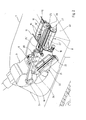
- an intermediate position is shown during the loading process, namely the transfer of a grenade 10 'from the magazine 8 to the loading arm 19.
- the section of the intermediate floor located there is designed as a pivotable slide 25 which in the Area of the rear chain is stored and can be tilted forward in a slight inclined position.
- a trough 25 is arranged in the transfer position of the magazine, which bridges the distance between the magazine 8 and the loading arm 19.
- the grenade 10 'tilted by means of the slide 25 can be displaced from the tilted position through the trough 25' into the brackets 21 by means of a thrust member 26 which engages on the bottom of the grenade and is arranged on a guide rod 27.
- the clip 21 is completely closed after the transfer, so that the grenade is now on the loading arm 19.
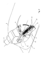
- the loading arm 19 automatically pivots under the weight of the grenade against the force of the return spring 24 down to the position shown in FIG. 3, in which the clamps 21 are opened.
- the opening takes place downwards, so that the grenade 10 ′ falls into the receptacle 23 of the attachment device 22.
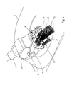
- the loading arm 19 Since the loading arm 19 is now lighter by the weight of the transferred grenade 10 ', it swivels back into its upper position (FIG. 4) under the action of the spring 24 and runs into the lock 20 in order to be automatically fixed again on the tower roof in this way .
- the receptacle 23 or the complete attachment device 22 pivots behind the weapon such that the grenade 10 'is in the attachment position (FIG. 4), from which it is accelerated into the weapon by means of the attachment device 22 and locked there (FIG. 5 ).
- the attachment device 22 has a rammer 45 which is driven by a chain 46.
- the chain 46 is guided in the manner of a block and tackle, which allows a translation of the path of the drive moving the chain over a longer path of the ram 45.
- the propellant charge is then manually added and finally the rotary closure 6 is closed.
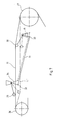
- FIGS. 6 and 7 show a modified version of the magazine 8.
- the front chain 11 is deflected downward over a greater length in the region of its upper strand 11 ', so that a plurality of grenades 10' are exposed at its tip and can be manually tempered, for example, by means of an electrically or magnetically active device 28.
- the grenade 10 ' for example on the far right in FIG. 6, can be in the take-over position and can be pushed directly out of this horizontal position into the loading arm 19, passing the chain 11 above the upper strand 11'.
- two chain supports 29, 30 see FIG.
- the handlebar 31 can be actuated via a kind of parallelogram by means of a handlebar 31 so that the chain length does not change despite the deflection movement.
- the handlebar 31 is connected at its ends via joints 32, 33 with angle levers 34, 35 which are mounted in a fixed position and at their other end carry the chain supports 29, 30 rotatably.
- One chain support 29 engages from above, the other chain support 30 from below on the front chain 11, which runs over chain wheels 36, 37.
- the grenades are thus transferred from the magazine 8 to the loading arm 19 while maintaining their axial orientation.
- marching lashing is provided for the grenades 10, which is indicated in FIG. 1 by way of example in connection with the grenade 10 ".
- a device 40 for positioning the grenades is located on the front chain 11 between adjacent bars 15 in each case.
- Each positioning device 40 has a lashing member 41 in the form of a fork which pivots on a horizontal axis 42 extending transversely to the grenade 10 ′′ is stored bar and can be placed on the tip of the grenade 10 ′′ or displaced in an inclined axis.
- the lashing member 41 swivels upward, so that the grenade is unobstructed from the magazine 6, can be exchangeably guided as a structural unit at the rear of the tower, so that an empty magazine can be exchanged quickly and easily for a complete, filled magazine
Landscapes
- Engineering & Computer Science (AREA)
- General Engineering & Computer Science (AREA)
- Aiming, Guidance, Guns With A Light Source, Armor, Camouflage, And Targets (AREA)
- Toys (AREA)
Applications Claiming Priority (2)
| Application Number | Priority Date | Filing Date | Title |
|---|---|---|---|
| DE4205963 | 1992-02-27 | ||
| DE4205963A DE4205963A1 (de) | 1992-02-27 | 1992-02-27 | Panzerhaubitze |
Publications (3)
| Publication Number | Publication Date |
|---|---|
| EP0557751A2 true EP0557751A2 (fr) | 1993-09-01 |
| EP0557751A3 EP0557751A3 (fr) | 1994-03-23 |
| EP0557751B1 EP0557751B1 (fr) | 1997-05-02 |
Family
ID=6452674
Family Applications (1)
| Application Number | Title | Priority Date | Filing Date |
|---|---|---|---|
| EP93101705A Expired - Lifetime EP0557751B1 (fr) | 1992-02-27 | 1993-02-04 | Obusier blindé comportant un bras de chargement pivotant et un magasin pour munitions du type à chaîne sans fin |
Country Status (7)
| Country | Link |
|---|---|
| EP (1) | EP0557751B1 (fr) |
| KR (1) | KR930018258A (fr) |
| DE (2) | DE4205963A1 (fr) |
| DK (1) | DK0557751T3 (fr) |
| ES (1) | ES2102536T3 (fr) |
| GR (1) | GR3024339T3 (fr) |
| NO (1) | NO303409B1 (fr) |
Cited By (7)
| Publication number | Priority date | Publication date | Assignee | Title |
|---|---|---|---|---|
| EP0731329A3 (fr) * | 1995-03-10 | 1996-11-20 | Martin Marietta Corp | Magasin pour munitions comportant un convoyeur sans fin |
| WO1998025097A1 (fr) * | 1996-12-02 | 1998-06-11 | Bofors Ab | Procede et dispositif pour chargeur de projectiles |
| US5880395A (en) * | 1996-10-26 | 1999-03-09 | Rheinmetall Industrie Ag | Gun turret assembly for an armored vehicle |
| US5965837A (en) * | 1996-01-31 | 1999-10-12 | Samsung Aerospace Industries, Ltd | Artillery shell carrier |
| SG82643A1 (en) * | 1999-10-01 | 2001-08-21 | Ordnance Dev And Engineering C | Ammunition handling system |
| FR3044753A1 (fr) * | 2015-12-08 | 2017-06-09 | Nexter Systems | Dispositif de manutention d'obus pour piece d'artillerie |
| WO2019201518A1 (fr) * | 2018-04-17 | 2019-10-24 | Rheinmetall Waffe Munition Gmbh | Chargeur automatique ainsi que véhicule équipé d'un chargeur automatique |
Families Citing this family (7)
| Publication number | Priority date | Publication date | Assignee | Title |
|---|---|---|---|---|
| DE19516706A1 (de) | 1995-05-06 | 1996-11-07 | Kuka Wehrtechnik Gmbh | Hubvorrichtung in einem Panzerfahrzeug |
| SE513006C2 (sv) | 1999-01-20 | 2000-06-19 | Bofors Weapon Sys Ab | Sätt och anordning för att hantera artillerigranater vid laddning av artilleripjäser |
| RU2153139C1 (ru) * | 1999-06-28 | 2000-07-20 | Государственное унитарное предприятие Конструкторское бюро приборостроения | Механизм подачи выстрелов артиллерийской установки |
| DE19932562B4 (de) * | 1999-07-13 | 2005-05-12 | Rheinmetall W & M Gmbh | Ladevorrichtung für eine grosskalibrige Waffe |
| DE10243956A1 (de) * | 2002-09-20 | 2004-04-15 | Carl Freudenberg Kg | Schaltungsanordnung für ein pulsweitenmoduliert ansteuerbares elektromagnetisches Regenerierventil zur Tankentlüftung eines Kraftfahrzeugs |
| DE102011000237B4 (de) * | 2011-01-20 | 2012-09-13 | Krauss-Maffei Wegmann Gmbh & Co. Kg | Munitionslift zum Aufmunitionieren eines Waffenturms, Waffenturm sowie Verfahren zum Aufmunitionieren eines Waffenturms |
| DE102022101213B3 (de) | 2022-01-19 | 2023-06-15 | Krauss-Maffei Wegmann Gmbh & Co. Kg | Magazin |
Family Cites Families (6)
| Publication number | Priority date | Publication date | Assignee | Title |
|---|---|---|---|---|
| FR2443041A1 (fr) * | 1978-11-30 | 1980-06-27 | France Etat | Dispositif de chargement automatique d'un canon integre dans une tourelle de char |
| DE3041866C2 (de) * | 1980-11-06 | 1986-01-30 | Krauss-Maffei AG, 8000 München | Vorrichtung zum Transport von Munition aus einem Munitionsbehälter zum Verschluß einer Waffe |
| DE3306934A1 (de) * | 1983-02-23 | 1984-08-30 | Rheinmetall GmbH, 4000 Düsseldorf | Waffenanlage |
| FR2545920B1 (fr) * | 1983-05-09 | 1985-07-05 | Hispano Suiza Sa | Materiel militaire comportant une tourelle munie d'une arme principale exterieure |
| DE3437588A1 (de) * | 1984-10-13 | 1986-04-24 | Rheinmetall GmbH, 4000 Düsseldorf | Ladeeinrichtung fuer geschuetze |
| DE4007172A1 (de) * | 1990-03-07 | 1991-09-12 | Kuka Wehrtechnik Gmbh | Vorrichtung zum laden von rohrwaffen |
-
1992
- 1992-02-27 DE DE4205963A patent/DE4205963A1/de not_active Ceased
-
1993
- 1993-02-04 ES ES93101705T patent/ES2102536T3/es not_active Expired - Lifetime
- 1993-02-04 DE DE59306305T patent/DE59306305D1/de not_active Expired - Fee Related
- 1993-02-04 DK DK93101705.7T patent/DK0557751T3/da active
- 1993-02-04 EP EP93101705A patent/EP0557751B1/fr not_active Expired - Lifetime
- 1993-02-25 NO NO930665A patent/NO303409B1/no not_active IP Right Cessation
- 1993-02-26 KR KR1019930002797A patent/KR930018258A/ko not_active Ceased
-
1997
- 1997-07-31 GR GR970401985T patent/GR3024339T3/el unknown
Cited By (9)
| Publication number | Priority date | Publication date | Assignee | Title |
|---|---|---|---|---|
| EP0731329A3 (fr) * | 1995-03-10 | 1996-11-20 | Martin Marietta Corp | Magasin pour munitions comportant un convoyeur sans fin |
| US5965837A (en) * | 1996-01-31 | 1999-10-12 | Samsung Aerospace Industries, Ltd | Artillery shell carrier |
| US5880395A (en) * | 1996-10-26 | 1999-03-09 | Rheinmetall Industrie Ag | Gun turret assembly for an armored vehicle |
| WO1998025097A1 (fr) * | 1996-12-02 | 1998-06-11 | Bofors Ab | Procede et dispositif pour chargeur de projectiles |
| SG82643A1 (en) * | 1999-10-01 | 2001-08-21 | Ordnance Dev And Engineering C | Ammunition handling system |
| FR3044753A1 (fr) * | 2015-12-08 | 2017-06-09 | Nexter Systems | Dispositif de manutention d'obus pour piece d'artillerie |
| EP3179194A1 (fr) * | 2015-12-08 | 2017-06-14 | NEXTER Systems | Dispositif de manutention d'obus pour pièce d'artillerie |
| WO2019201518A1 (fr) * | 2018-04-17 | 2019-10-24 | Rheinmetall Waffe Munition Gmbh | Chargeur automatique ainsi que véhicule équipé d'un chargeur automatique |
| US11268775B2 (en) | 2018-04-17 | 2022-03-08 | Rheinmetall Waffe Munition Gmbh | Auto-loader and vehicle comprising an auto-loader |
Also Published As
| Publication number | Publication date |
|---|---|
| NO303409B1 (no) | 1998-07-06 |
| KR930018258A (ko) | 1993-09-21 |
| NO930665D0 (no) | 1993-02-25 |
| EP0557751A3 (fr) | 1994-03-23 |
| DK0557751T3 (da) | 1997-11-03 |
| NO930665L (no) | 1993-08-30 |
| EP0557751B1 (fr) | 1997-05-02 |
| ES2102536T3 (es) | 1997-08-01 |
| GR3024339T3 (en) | 1997-10-31 |
| DE4205963A1 (de) | 1993-09-02 |
| DE59306305D1 (de) | 1997-06-05 |
Similar Documents
| Publication | Publication Date | Title |
|---|---|---|
| DE2826136C3 (de) | Vorrichtung für den Munitionstransport aus einem gepanzerten Fahrzeug zu einem auf einer Plattform fest angeordneten scheitellafettierten Geschütz | |
| DE2837303C2 (de) | Vorrichtung für Munitionslagerung und -transport bei einem Panzerfahrzeug mit einem scheitellafettierten Geschütz | |
| EP0557751B1 (fr) | Obusier blindé comportant un bras de chargement pivotant et un magasin pour munitions du type à chaîne sans fin | |
| EP0178484A1 (fr) | Chargeur pour canons | |
| DE69815955T2 (de) | Einrichtung zum Laden von Granatwerfern | |
| DE3409018A1 (de) | Munitionsbehaelter einer automatischen ladeeinrichtung | |
| DE2948146A1 (de) | Automatische ladevorrichtung fuer in einen panzerwagenturm eingebaute feuerwaffen | |
| DE1140109B (de) | Ladevorrichtung fuer Geschuetze | |
| DE619896C (de) | Munitionszufuehreinrichtung fuer zwei zum gemeinsamen Rahmen der Seitenrichtung verbundene Geschuetze | |
| EP0640805B1 (fr) | Dispositif d'alimentation en munitions du canon d'un char | |
| EP0742419B1 (fr) | Dispositif élevateur à l'intérieur d'un taur | |
| EP0301259A1 (fr) | Véhicule de combat | |
| DE2501424A1 (de) | Munitionsaufnahme- und ladevorrichtung fuer eine grosskalibrige feuerwaffe | |
| DE2215398B2 (de) | Lafettiertes Mehrrohrgeschütz | |
| DE3702426C2 (fr) | ||
| DE964210C (de) | Panzerfahrzeug | |
| DE3701712C2 (fr) | ||
| DE634474C (de) | Munitionszufuhreinrichtung fuer zwei zum gemeinsamen Nehmen der Seitenrichtung verbundene Geschuetze | |
| DE3219800C2 (de) | Vorrichtung zum Zuführen von Munition zu einer Maschinenwaffe | |
| EP0635695B1 (fr) | Véhicule de combat, en particulier obusier, comportant des magasins de munitions | |
| EP0221935A1 (fr) | Dispositif de transfert de cartouches de munition d'un chargeur de bati a un chargeur de tourelle. | |
| DE965684C (de) | Lafette fuer Feuerwaffen | |
| DE3342223C2 (de) | Patronenzuführvorrichtung | |
| DE4123338A1 (de) | Kampfpanzerturm | |
| DE2543155B2 (de) | Großkalibrige Waffe für Steil- und Flachfeuer |
Legal Events
| Date | Code | Title | Description |
|---|---|---|---|
| PUAI | Public reference made under article 153(3) epc to a published international application that has entered the european phase |
Free format text: ORIGINAL CODE: 0009012 |
|
| AK | Designated contracting states |
Kind code of ref document: A2 Designated state(s): BE DE DK ES GR NL PT |
|
| PUAL | Search report despatched |
Free format text: ORIGINAL CODE: 0009013 |
|
| AK | Designated contracting states |
Kind code of ref document: A3 Designated state(s): BE DE DK ES GR NL PT |
|
| 17P | Request for examination filed |
Effective date: 19940226 |
|
| 17Q | First examination report despatched |
Effective date: 19950814 |
|
| GRAG | Despatch of communication of intention to grant |
Free format text: ORIGINAL CODE: EPIDOS AGRA |
|
| GRAH | Despatch of communication of intention to grant a patent |
Free format text: ORIGINAL CODE: EPIDOS IGRA |
|
| GRAH | Despatch of communication of intention to grant a patent |
Free format text: ORIGINAL CODE: EPIDOS IGRA |
|
| GRAA | (expected) grant |
Free format text: ORIGINAL CODE: 0009210 |
|
| AK | Designated contracting states |
Kind code of ref document: B1 Designated state(s): BE DE DK ES GR NL PT |
|
| REF | Corresponds to: |
Ref document number: 59306305 Country of ref document: DE Date of ref document: 19970605 |
|
| REG | Reference to a national code |
Ref country code: ES Ref legal event code: FG2A Ref document number: 2102536 Country of ref document: ES Kind code of ref document: T3 |
|
| PG25 | Lapsed in a contracting state [announced via postgrant information from national office to epo] |
Ref country code: PT Effective date: 19970804 |
|
| REG | Reference to a national code |
Ref country code: GR Ref legal event code: FG4A Free format text: 3024339 |
|
| REG | Reference to a national code |
Ref country code: DK Ref legal event code: T3 |
|
| PLBE | No opposition filed within time limit |
Free format text: ORIGINAL CODE: 0009261 |
|
| STAA | Information on the status of an ep patent application or granted ep patent |
Free format text: STATUS: NO OPPOSITION FILED WITHIN TIME LIMIT |
|
| 26N | No opposition filed | ||
| NLS | Nl: assignments of ep-patents |
Owner name: RHEINMETALL LANDSYSTEME GMBH |
|
| REG | Reference to a national code |
Ref country code: ES Ref legal event code: PC2A |
|
| PGFP | Annual fee paid to national office [announced via postgrant information from national office to epo] |
Ref country code: GR Payment date: 20040123 Year of fee payment: 12 Ref country code: DK Payment date: 20040123 Year of fee payment: 12 |
|
| PGFP | Annual fee paid to national office [announced via postgrant information from national office to epo] |
Ref country code: NL Payment date: 20040216 Year of fee payment: 12 |
|
| PGFP | Annual fee paid to national office [announced via postgrant information from national office to epo] |
Ref country code: ES Payment date: 20040223 Year of fee payment: 12 |
|
| PGFP | Annual fee paid to national office [announced via postgrant information from national office to epo] |
Ref country code: BE Payment date: 20040308 Year of fee payment: 12 |
|
| PG25 | Lapsed in a contracting state [announced via postgrant information from national office to epo] |
Ref country code: ES Free format text: LAPSE BECAUSE OF NON-PAYMENT OF DUE FEES Effective date: 20050205 |
|
| PGFP | Annual fee paid to national office [announced via postgrant information from national office to epo] |
Ref country code: DE Payment date: 20050219 Year of fee payment: 13 |
|
| PG25 | Lapsed in a contracting state [announced via postgrant information from national office to epo] |
Ref country code: DK Free format text: LAPSE BECAUSE OF NON-PAYMENT OF DUE FEES Effective date: 20050228 Ref country code: BE Free format text: LAPSE BECAUSE OF NON-PAYMENT OF DUE FEES Effective date: 20050228 |
|
| BERE | Be: lapsed |
Owner name: *RHEINMETALL LANDSYSTEME G.M.B.H. Effective date: 20050228 |
|
| PG25 | Lapsed in a contracting state [announced via postgrant information from national office to epo] |
Ref country code: NL Free format text: LAPSE BECAUSE OF NON-PAYMENT OF DUE FEES Effective date: 20050901 |
|
| PG25 | Lapsed in a contracting state [announced via postgrant information from national office to epo] |
Ref country code: GR Free format text: LAPSE BECAUSE OF NON-PAYMENT OF DUE FEES Effective date: 20050905 |
|
| REG | Reference to a national code |
Ref country code: DK Ref legal event code: EBP |
|
| NLV4 | Nl: lapsed or anulled due to non-payment of the annual fee |
Effective date: 20050901 |
|
| REG | Reference to a national code |
Ref country code: ES Ref legal event code: FD2A Effective date: 20050205 |
|
| PG25 | Lapsed in a contracting state [announced via postgrant information from national office to epo] |
Ref country code: DE Free format text: LAPSE BECAUSE OF NON-PAYMENT OF DUE FEES Effective date: 20060901 |
|
| BERE | Be: lapsed |
Owner name: *RHEINMETALL LANDSYSTEME G.M.B.H. Effective date: 20050228 |