EP0557960A2 - Dispositif de traitement de pièces de monnaie pour machines de vente automatiques - Google Patents
Dispositif de traitement de pièces de monnaie pour machines de vente automatiques Download PDFInfo
- Publication number
- EP0557960A2 EP0557960A2 EP93102863A EP93102863A EP0557960A2 EP 0557960 A2 EP0557960 A2 EP 0557960A2 EP 93102863 A EP93102863 A EP 93102863A EP 93102863 A EP93102863 A EP 93102863A EP 0557960 A2 EP0557960 A2 EP 0557960A2
- Authority
- EP
- European Patent Office
- Prior art keywords
- coin
- coins
- entire
- recovery
- storage cylinders
- Prior art date
- Legal status (The legal status is an assumption and is not a legal conclusion. Google has not performed a legal analysis and makes no representation as to the accuracy of the status listed.)
- Granted
Links
- 238000011084 recovery Methods 0.000 claims abstract description 75
- 230000007246 mechanism Effects 0.000 claims abstract description 27
- 230000008859 change Effects 0.000 claims abstract description 26
- 238000007599 discharging Methods 0.000 claims abstract description 26
- 238000001514 detection method Methods 0.000 claims abstract description 16
- 230000004044 response Effects 0.000 claims abstract description 8
- 238000000034 method Methods 0.000 claims description 29
- 230000008569 process Effects 0.000 claims description 29
- 238000012423 maintenance Methods 0.000 description 3
- 230000004913 activation Effects 0.000 description 1
- 238000004891 communication Methods 0.000 description 1
- 230000003247 decreasing effect Effects 0.000 description 1
- 230000000977 initiatory effect Effects 0.000 description 1
Images



Classifications
-
- G—PHYSICS
- G07—CHECKING-DEVICES
- G07F—COIN-FREED OR LIKE APPARATUS
- G07F9/00—Details other than those peculiar to special kinds or types of apparatus
- G07F9/006—Details of the software used for the vending machines
-
- G—PHYSICS
- G07—CHECKING-DEVICES
- G07F—COIN-FREED OR LIKE APPARATUS
- G07F1/00—Coin inlet arrangements; Coins specially adapted to operate coin-freed mechanisms
- G07F1/02—Coin slots
-
- G—PHYSICS
- G07—CHECKING-DEVICES
- G07F—COIN-FREED OR LIKE APPARATUS
- G07F5/00—Coin-actuated mechanisms; Interlocks
- G07F5/24—Coin-actuated mechanisms; Interlocks with change-giving
-
- G—PHYSICS
- G07—CHECKING-DEVICES
- G07F—COIN-FREED OR LIKE APPARATUS
- G07F9/00—Details other than those peculiar to special kinds or types of apparatus
- G07F9/04—Means for returning surplus or unused coins
Definitions
- the invention relates to a coin processor for use with automatic vending machines. More particularly, it relates to an improved coin recovery system of such coin processor.
- An object of the invention is to provide an improved, yet low -cost, coin processor for use with automatic vending machines, having a high coin recovery efficiency.
- a coin processor for use with automatic vending machine comprises: a coin classifying mechanism for classifying coins deposited in the automatic vending machine; a multiplicity of coin storage cylinders for storing the coins classified by the coin classifying mechanism; change sensors provided one for each said coin cylinder for sensing predetermined number of coins in the cylinders; a multiplicity of coin discharging mechanisms provided one for each said coin storage cylinder; a multiplicity of coin recovery switches for enabling said discharging mechanisms so as to recover coins from said storage cylinders; a controller for controlling the operations of said coin discharging mechanisms such that said coin discharging mechanisms discharge coins from the coin storage cylinders one by one in response to signals received from said coin recovery switch, and the coin processor is characterized in that said coin recovery switches comprise an entire coin recovery switch for recovering entire coins from the coin storage cylinders, and a multiplicity of one -type coin recovery switches for recovering from said storage cylinders specific types of coins designated by said coin recovery switches operated;
- the controller preferably comprises initial value setting means for presetting an initial number for each of the coin storage cylinders, said initial number being greater than the maximum number that the change detection sensor can sense; and a counter for counting down the count stored in the counter by one every time the coin discharging mechanism associated with the counter is operated after the corresponding change sensor sensed the preset initial number, and for stopping the coin discharging mechanism when the number is counted down to zero.
- the coin processor may be manufactured less costly and has high coin recovery performance.
- the controller preferably comprises stopping means for stopping coin discharge process initiated by a first operation of the entire coin recovery switch, in response to a second operation of the entire coin recovery switch.
- Such stopping means described above enables stopping of the coin recovery operation in case of emergency.
- the controller preferably comprises shift means for stopping the current coin discharge process initiated by the operation of the entire coin recovery switch if one of the one-type coin recovery switches is operated during the coin discharge process, and for executing the coin recovery operation instructed by said one-type coin recovery switch.
- the controller preferably comprises selection means for switching from one coin discharge process initiated by one of the one-type coin recovery switches to another coin discharge process for another type of coins if another one of the one-type coin recovery switches is operated.
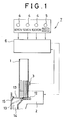
- Fig. 1 is a schematic view of a controller in communication with other components of a coin processor according to the invention.
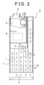
- Fig. 2 is a front view of the coin processor of Fig. 1.
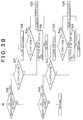
- Fig. 3 is a flowchart for a "key input" sub-routine executed by the controller of the coin processor of Fig. 1.
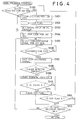
- Figs. 4 through 6 all together show a flowchart for a "coin discharge process" sub-routine executed by the controller of the coin processor of Fig. 1.
- a coin processor 7 of the invention comprising a multiplicity of coin storage cylinders 1 for storing coins which were deposited by customers and classified by values as stated below; coin discharging mechanisms 2 for discharging coins from the respective coin storage cylinders 1; change detection sensors 3 for sensing if coins remain in the cylinders more than a predetermined amount; coin recovery switches 4 for initiating a coin recovery operation for a designated type of coins from a corresponding one of the coin storage cylinders 1; an entire coin recovery switch 5 for recovering all types of coins stored in the coin storage cylinders 1; a controller 6 including a microprocessor (CPU), ROM, and RAM for controlling the operations of the coin storage cylinders 1, coin discharging mechanisms 2, change detection sensors 3, coin recovery switches 4, and the entire coin recovery switch 5.
- CPU microprocessor
- ROM read only memory
- RAM random access memory
- Coins deposited in an automatic vending machine through a coin slot 8 of the coin processor 7 will drop into a coin classifying mechanism 9 where coins are tested for their genuineness and values. The coins are classified by values and then stored in respective coin storage cylinders 1 according to their values.
- the controller 6 receives a signal indicative of genuineness and values of the deposited coins, signals from the change detection sensors 3 indicative of whether or not a number of coins exceeding a preset number of coins is present in each coin storage cylinder, and signals from merchandise buttons mounted on a control panel provided on the vending machine, indicative of the prices of the merchandise selected.
- the controller 6 calculates the amount of change, determines on the basis of these signals if there is enough change, and, if it is, determines if the merchandise can be vendable, and executes a change refund operation following the vending.
- the change refund operation includes activation of levers 12 provided in respective coin discharging mechanisms 2 in response to the instruction given by the controller 6.
- the lever when activated, forces the lowest coin 13 in the coin storage cylinder 1 into a coin discharge path 14.
- the coin 13 forced into the coin discharge path 14 is first pushed in a horizontal direction, abuts on a slanted portion 15 of the discharge path 14, and drops downward.
- the CPU of controller 6 executes various sub-routines shown by a flowchart in Figs. 3 - 6. After executing any one of the sub -routines, the CPU returns to a main process (not shown) related to other portions of a vending operation. For example, when the CPU enters a "key input" sub-routine shown in Fig. 3 from the main routine, it returns once to the main routine after the completion of the sub -routine, and then enters another sub -routine such as "coin discharge process" sub-routine as shown in Figs. 4-6. It should be noted that, although not shown in the flowchart, there are many flags involved in the sub-routines, which are all set to 0 (i.e. cleared) at the time of initialization.
- the controller 6 When the controller 6 is in its standby condition, it repeats a process to enter from the main routine to the sub-routine "key input" as shown in Fig. 3, undergoes steps S10, S20,S30, and S40 and then returns to the main routine. Under this condition, if the entire coin recovery switch 5 is pressed, the CPU recognize the operation of the switch 5 in the step S10, proceeds to step S11 where a determination is made whether a flag indicative if the controller 6 is currently in coin recovery operation and denoted by CCR flag (implying Current Coin Recovery flag) in the Figure, is set or cleared (to be 1 or 0, respectively).
- CCR flag implying Current Coin Recovery flag
- step S12 all the "coin type selection" flags, denoted by CTS flag (for 10, 50, and 100 yen) are set to 1, and returns to the main routine.
- Step S100 a determination is made in the Step S100 as to the condition of the CTS flag for 100 yen. If the flag is set, the CPU proceeds to the step S101 to execute automatic coin recovery operation for 100 yen coins.
- step S101 the CPU clears the 100 yen selection flag and proceeds to step S102 to set the CCR flag indicating that the 100 yen coin recovery operation is undergoing.
- the processor takes into account the precision of the change detection sensors. The actual number of coins that can be counted correctly by the change detection sensor ranges from 13 to 19, inclusive for 100 yen coins. Therefore, in the step S103, a maximum countable number for the change detection sensor, which is 20 in the example described herein, is set in a null change counter (referred to NC counter) associated with the change detection sensor for 100 yen coins.
- NC counter null change counter
- the CPU instructs the controller 6 to generate a signal indicative of discharging 100 yen coins to the coin corresponding discharging mechanism 2 so that the lever 12 of the coin storage cylinder 1 for 100 yen coins.
- the CPU confirms the end of the coin discharge process in step S106, and proceeds to step S107 where the coin discharging signal generated from the controller 6 to the coin discharging mechanism 2 is stopped.
- the CPU checks the state of the signal received from the change detection sensor 3.
- step S112 a determination is made if the CCR flag is set. Since the flag has been now set in the step S102, the CPU proceeds to step S113, where a determination is made if either another coin selection switch 4 or the entire coin recovery switch 5 is operated during the current coin recovery operation. If not, the CPU returns again to the step S105 to continue the current coin recovery operation for 100 yen coins.
- the CPU branches from the step S113 back to the main routine once, and then enter the "key in" sub-routine shown in Fig. 3.
- the CPU goes to the step S11 via the step S10.
- the CCR flag indicating that the coin recovery process is undergoing, is found to be set, since the coin recovery operation is undergoing.
- the CPU therefore proceeds to the step S13 where the CCR flag is cleared.
- the step S14 all the flags are cleared.
- the CPU then returns to the main routine.
- the CPU returns from the main routine to the " coin discharge process" of Fig. 4, it finds in the step S100 that the coin type selection flag, CTS flag, for 100 yen coins is cleared, so that the CPU will not proceed to the subsequent steps that follow S105, but stop the coin discharge process and return to the standby condition.
- step S108 the signal outputted from the change detection sensor 3 for the 100 yen coins eventually changes from "YES" to "NONE", which causes the CPU to proceed to step S109.
- the actual number of coins is between 13 and 19.
- the NC counter counts down its count (referred to as NC count) by one from the value "20" set in the null change counter in the step S103.
- step S110 the NC count of the NC counter is judged if it is 0.
- step S112 the CPU proceeds to step S112, S113, and exits to the step S105.
- This sequence of the steps constitutes a loop involving S105 through S113.
- the CPU will repeat this loop until all the 100 yen coins are discharged from the 100 yen cylinder completely.
- the initial count of the NC counter is 20 which is greater than actual number of coins in the cylinder, i.e. a number between 13 and 19, the loop is further repeated until the NC count is decreased to 0.
- the steps S105 through S107 are repeated for the empty cylinder.
- step S110 When the NC counter is counted down to 0, it is determined in the step S110 that the coin recovery process is completed. The CPU then proceeds to step S111 to clear the CCR flag and returns to step S100. Since the coin selection flag has been cleared for 100 yen coins, the CPU proceeds from step S100 to step S200 shown in Fig. 5, and further to steps S201 through S213 on account of the fact that the coin selection flag is set in the step S200. Execution of the steps S201 to S213 are similar to the corresponding steps S100 through S113 for 100 yen coins except that the relevant coin storage cylinder is now the one for 50 yen coins so that 50 yen coins are now discharged.
- coin recovery operations for 100 yen, 50 yen, and 10 yen are performed in this order, reflecting the order of priority for higher values of coins.
- a particular one of interest is operated by the operator. For example, suppose that only 10 yen coins are to be recovered.
- the CPU enters from the main routine to the "key input" sub-routine, and jumps from the step S10 to the step S20, from where it proceeds to the step S21 since the switch for the 10 yen coins has been operated. Since the CCR flag is not set, the CPU proceeds to the step S22 and sets CTS flag for the 10 yen coins, and returns to the main routine.
- step S300 where the CPU finds that the CTS flag is set for 10 yen coins, so that it proceeds to step S301 and instructs a coin recovery operation for 10 yen coins, in just the same manner as for previously described coin recovery operation for 100 yen coins.
- Any current coin coin discharge process may be interrupted by pressing another coin recovery switch 4 during the operation.
- the CPU will then jump from the current operation to a newly commanded operation. For example, if the coin recovery button 4 for 10 yen coins is pressed during the coin recovery operation for 100 yen coins, the operation of the switch for 10 yen coins is recognized in the step S113 during the coin recovery operation for 100 yen coins, as seen in Fig. 4. Thus, the discharge process for the 100 yen coins will be stopped then and the CPU returns to the main routine.
- the CPU then enters from the main routine the "key input" sub-routine, proceeds to step S21 via steps S10, S20, and finds that the CCR flag F is set due to the fact that coin recovery operation for 100 yen had been in process.
- step S24 it determines whether the coin code set in the RAM is for 10 yen. Since the operation had been for 100 yen, the coin code set in the RAM is for 100 yen. Thus, the CPU, now in step S22, sets a CTS flag for 10 yen and returns to main routine.
- the process enters from the main routine the "coin discharge process" shown in Fig. 4. The process jumps from step S100 to step S200 of Fig. 5, and further to step S300, where CTS flag for 10 yen is found to be set, so that a coin recovery operation is executed for 10 yen coins. This operation consists of steps S301 through S313. It would be understood that this operation is similar to the foregoing coin recovery operations for 100 yen and 50 yen.
Landscapes
- Physics & Mathematics (AREA)
- General Physics & Mathematics (AREA)
- Control Of Vending Devices And Auxiliary Devices For Vending Devices (AREA)
Applications Claiming Priority (2)
| Application Number | Priority Date | Filing Date | Title |
|---|---|---|---|
| JP04043192A JP3133456B2 (ja) | 1992-02-28 | 1992-02-28 | 自動販売機の硬貨処理装置 |
| JP43192/92 | 1992-02-28 |
Publications (3)
| Publication Number | Publication Date |
|---|---|
| EP0557960A2 true EP0557960A2 (fr) | 1993-09-01 |
| EP0557960A3 EP0557960A3 (en) | 1994-08-17 |
| EP0557960B1 EP0557960B1 (fr) | 1996-10-16 |
Family
ID=12657063
Family Applications (1)
| Application Number | Title | Priority Date | Filing Date |
|---|---|---|---|
| EP93102863A Expired - Lifetime EP0557960B1 (fr) | 1992-02-28 | 1993-02-24 | Dispositif de traitement de pièces de monnaie pour machines de vente automatiques |
Country Status (5)
| Country | Link |
|---|---|
| US (1) | US5380242A (fr) |
| EP (1) | EP0557960B1 (fr) |
| JP (1) | JP3133456B2 (fr) |
| KR (1) | KR960001454B1 (fr) |
| DE (1) | DE69305387T2 (fr) |
Cited By (1)
| Publication number | Priority date | Publication date | Assignee | Title |
|---|---|---|---|---|
| EP0689171A3 (fr) * | 1994-06-03 | 1996-03-13 | Nat Rejectors Gmbh | Dispositif d'examen de pièces de monnaie |
Families Citing this family (4)
| Publication number | Priority date | Publication date | Assignee | Title |
|---|---|---|---|---|
| DE19518172A1 (de) * | 1995-05-19 | 1996-11-21 | Wurster Gerd | Spritzkabine |
| JP3766200B2 (ja) * | 1998-02-18 | 2006-04-12 | 株式会社日本コンラックス | 貨幣処理方法および装置 |
| US6508700B2 (en) * | 2000-01-14 | 2003-01-21 | Kabushiki Kaisha Nippon Conlux | Coin processing device |
| EP1180747B1 (fr) * | 2000-08-10 | 2004-11-17 | Mars Incorporated | Dipositif de manipulation d'argent |
Family Cites Families (10)
| Publication number | Priority date | Publication date | Assignee | Title |
|---|---|---|---|---|
| US4364404A (en) * | 1980-10-15 | 1982-12-21 | Kabushiki Kaisha Nippon Coicno | Inventory device in automatic vending machine |
| EP0167181B2 (fr) * | 1981-09-29 | 1995-02-01 | Mars Incorporated | Dispositif pour le traitement de pièces de monnaie |
| GB2137793B (en) * | 1983-02-08 | 1986-06-04 | Mars Inc | Coin handling apparatus |
| US4558711A (en) * | 1983-07-08 | 1985-12-17 | Glory Kogyo Kabushiki Kaisha | Coin processing apparatus |
| IT1179554B (it) * | 1984-01-13 | 1987-09-16 | Urmet Spa | Gettoniera elettronica funzionante con monete di diverse pezzature e con gettoni particolarmente per uso telefonico pubblico |
| EP0287049B1 (fr) * | 1987-04-13 | 1993-12-22 | Th. Bergmann GmbH & Co. | Procédé de liquidation et d'encaissement de machines automatiques actionnées par pièces de monnaie et installation pour la réalisation de ce procédé |
| JPS6429665A (en) * | 1987-07-21 | 1989-01-31 | Mazda Motor | Fuel feed device for alcohol fuel engine |
| FR2619943B1 (fr) * | 1987-08-26 | 1990-01-19 | Crouzet Sa | Procede et dispositif d'encaissement |
| DE3882706D1 (de) * | 1988-08-25 | 1993-09-02 | Scheidt & Bachmann Gmbh | Anlage mit einer mehrzahl von selbstkassierenden warenverkaufs- oder dienstleistungsautomaten. |
| JPS6479172A (en) * | 1988-08-30 | 1989-03-24 | Seiko Epson Corp | Liquid crystal compound |
-
1992
- 1992-02-28 JP JP04043192A patent/JP3133456B2/ja not_active Expired - Fee Related
-
1993
- 1993-02-23 US US08/021,458 patent/US5380242A/en not_active Expired - Fee Related
- 1993-02-24 DE DE69305387T patent/DE69305387T2/de not_active Expired - Fee Related
- 1993-02-24 EP EP93102863A patent/EP0557960B1/fr not_active Expired - Lifetime
- 1993-02-26 KR KR1019930002719A patent/KR960001454B1/ko not_active Expired - Fee Related
Cited By (1)
| Publication number | Priority date | Publication date | Assignee | Title |
|---|---|---|---|---|
| EP0689171A3 (fr) * | 1994-06-03 | 1996-03-13 | Nat Rejectors Gmbh | Dispositif d'examen de pièces de monnaie |
Also Published As
| Publication number | Publication date |
|---|---|
| JP3133456B2 (ja) | 2001-02-05 |
| DE69305387T2 (de) | 1997-04-03 |
| KR960001454B1 (ko) | 1996-01-30 |
| EP0557960B1 (fr) | 1996-10-16 |
| EP0557960A3 (en) | 1994-08-17 |
| KR930018431A (ko) | 1993-09-21 |
| DE69305387D1 (de) | 1996-11-21 |
| JPH05242329A (ja) | 1993-09-21 |
| US5380242A (en) | 1995-01-10 |
Similar Documents
| Publication | Publication Date | Title |
|---|---|---|
| US4636963A (en) | Control system for an automatic vending machine | |
| US4679150A (en) | Automatic vending machine with discount function | |
| US4150740A (en) | Money exchanging system | |
| US5380242A (en) | Coin processor for use with automatic vending machines | |
| US4347925A (en) | Malfunction indication device for a vending machine | |
| US6536577B2 (en) | Coin handling method and device | |
| EP0569956B1 (fr) | Dispositif de traitement de pièces de monnaie | |
| US6918826B2 (en) | Coin treating device | |
| JPS6343793B2 (fr) | ||
| JP4375229B2 (ja) | 硬貨処理装置 | |
| EP0484824A2 (fr) | Mécanisme de traitement de pièces de monnaie pour machines de vente | |
| JP4333504B2 (ja) | 自動販売機の硬貨処理装置およびつり銭回収処理プログラム | |
| JPS6245255Y2 (fr) | ||
| JPH0331986A (ja) | 自動販売機の釣銭制御装置 | |
| JP4333493B2 (ja) | 硬貨識別装置 | |
| KR0133649B1 (ko) | 자동판매기의 잔돈반환 제어방법 | |
| JP3018855B2 (ja) | 台間玉貸機 | |
| JPH0129665Y2 (fr) | ||
| JPH05143835A (ja) | 自動販売機 | |
| JPH087493Y2 (ja) | 自動販売機の硬貨回収装置 | |
| KR0127887B1 (ko) | 자동판매기의 경화처리장치 | |
| JPS6127025Y2 (fr) | ||
| JPH0319015Y2 (fr) | ||
| JPS6213182Y2 (fr) | ||
| JPH0525159B2 (fr) |
Legal Events
| Date | Code | Title | Description |
|---|---|---|---|
| PUAI | Public reference made under article 153(3) epc to a published international application that has entered the european phase |
Free format text: ORIGINAL CODE: 0009012 |
|
| AK | Designated contracting states |
Kind code of ref document: A2 Designated state(s): DE FR GB |
|
| PUAL | Search report despatched |
Free format text: ORIGINAL CODE: 0009013 |
|
| AK | Designated contracting states |
Kind code of ref document: A3 Designated state(s): DE FR GB |
|
| 17P | Request for examination filed |
Effective date: 19940923 |
|
| GRAG | Despatch of communication of intention to grant |
Free format text: ORIGINAL CODE: EPIDOS AGRA |
|
| 17Q | First examination report despatched |
Effective date: 19960117 |
|
| GRAH | Despatch of communication of intention to grant a patent |
Free format text: ORIGINAL CODE: EPIDOS IGRA |
|
| GRAH | Despatch of communication of intention to grant a patent |
Free format text: ORIGINAL CODE: EPIDOS IGRA |
|
| GRAA | (expected) grant |
Free format text: ORIGINAL CODE: 0009210 |
|
| AK | Designated contracting states |
Kind code of ref document: B1 Designated state(s): DE FR GB |
|
| PG25 | Lapsed in a contracting state [announced via postgrant information from national office to epo] |
Ref country code: FR Effective date: 19961016 |
|
| REF | Corresponds to: |
Ref document number: 69305387 Country of ref document: DE Date of ref document: 19961121 |
|
| EN | Fr: translation not filed | ||
| EN | Fr: translation not filed |
Free format text: CORRECTIONS |
|
| PLBE | No opposition filed within time limit |
Free format text: ORIGINAL CODE: 0009261 |
|
| STAA | Information on the status of an ep patent application or granted ep patent |
Free format text: STATUS: NO OPPOSITION FILED WITHIN TIME LIMIT |
|
| 26N | No opposition filed | ||
| REG | Reference to a national code |
Ref country code: GB Ref legal event code: IF02 |
|
| PGFP | Annual fee paid to national office [announced via postgrant information from national office to epo] |
Ref country code: GB Payment date: 20020227 Year of fee payment: 10 |
|
| PGFP | Annual fee paid to national office [announced via postgrant information from national office to epo] |
Ref country code: DE Payment date: 20020314 Year of fee payment: 10 |
|
| PG25 | Lapsed in a contracting state [announced via postgrant information from national office to epo] |
Ref country code: GB Free format text: LAPSE BECAUSE OF NON-PAYMENT OF DUE FEES Effective date: 20030224 |
|
| PG25 | Lapsed in a contracting state [announced via postgrant information from national office to epo] |
Ref country code: DE Free format text: LAPSE BECAUSE OF NON-PAYMENT OF DUE FEES Effective date: 20030902 |
|
| GBPC | Gb: european patent ceased through non-payment of renewal fee |