EP0558095A2 - Dispositif pour la commande d'un réfrigérateur à deux évaporateurs et à deux ventilateurs munis de commandes indépendantes de température - Google Patents
Dispositif pour la commande d'un réfrigérateur à deux évaporateurs et à deux ventilateurs munis de commandes indépendantes de température Download PDFInfo
- Publication number
- EP0558095A2 EP0558095A2 EP93104589A EP93104589A EP0558095A2 EP 0558095 A2 EP0558095 A2 EP 0558095A2 EP 93104589 A EP93104589 A EP 93104589A EP 93104589 A EP93104589 A EP 93104589A EP 0558095 A2 EP0558095 A2 EP 0558095A2
- Authority
- EP
- European Patent Office
- Prior art keywords
- evaporator
- fresh food
- compartment
- situated
- fan
- Prior art date
- Legal status (The legal status is an assumption and is not a legal conclusion. Google has not performed a legal analysis and makes no representation as to the accuracy of the status listed.)
- Granted
Links
Images




Classifications
-
- F—MECHANICAL ENGINEERING; LIGHTING; HEATING; WEAPONS; BLASTING
- F25—REFRIGERATION OR COOLING; COMBINED HEATING AND REFRIGERATION SYSTEMS; HEAT PUMP SYSTEMS; MANUFACTURE OR STORAGE OF ICE; LIQUEFACTION SOLIDIFICATION OF GASES
- F25D—REFRIGERATORS; COLD ROOMS; ICE-BOXES; COOLING OR FREEZING APPARATUS NOT OTHERWISE PROVIDED FOR
- F25D29/00—Arrangement or mounting of control or safety devices
-
- F—MECHANICAL ENGINEERING; LIGHTING; HEATING; WEAPONS; BLASTING
- F25—REFRIGERATION OR COOLING; COMBINED HEATING AND REFRIGERATION SYSTEMS; HEAT PUMP SYSTEMS; MANUFACTURE OR STORAGE OF ICE; LIQUEFACTION SOLIDIFICATION OF GASES
- F25B—REFRIGERATION MACHINES, PLANTS OR SYSTEMS; COMBINED HEATING AND REFRIGERATION SYSTEMS; HEAT PUMP SYSTEMS
- F25B1/00—Compression machines, plants or systems with non-reversible cycle
- F25B1/10—Compression machines, plants or systems with non-reversible cycle with multi-stage compression
-
- F—MECHANICAL ENGINEERING; LIGHTING; HEATING; WEAPONS; BLASTING
- F25—REFRIGERATION OR COOLING; COMBINED HEATING AND REFRIGERATION SYSTEMS; HEAT PUMP SYSTEMS; MANUFACTURE OR STORAGE OF ICE; LIQUEFACTION SOLIDIFICATION OF GASES
- F25B—REFRIGERATION MACHINES, PLANTS OR SYSTEMS; COMBINED HEATING AND REFRIGERATION SYSTEMS; HEAT PUMP SYSTEMS
- F25B5/00—Compression machines, plants or systems, with several evaporator circuits, e.g. for varying refrigerating capacity
- F25B5/04—Compression machines, plants or systems, with several evaporator circuits, e.g. for varying refrigerating capacity arranged in series
-
- F—MECHANICAL ENGINEERING; LIGHTING; HEATING; WEAPONS; BLASTING
- F25—REFRIGERATION OR COOLING; COMBINED HEATING AND REFRIGERATION SYSTEMS; HEAT PUMP SYSTEMS; MANUFACTURE OR STORAGE OF ICE; LIQUEFACTION SOLIDIFICATION OF GASES
- F25D—REFRIGERATORS; COLD ROOMS; ICE-BOXES; COOLING OR FREEZING APPARATUS NOT OTHERWISE PROVIDED FOR
- F25D17/00—Arrangements for circulating cooling fluids; Arrangements for circulating gas, e.g. air, within refrigerated spaces
- F25D17/04—Arrangements for circulating cooling fluids; Arrangements for circulating gas, e.g. air, within refrigerated spaces for circulating air, e.g. by convection
- F25D17/06—Arrangements for circulating cooling fluids; Arrangements for circulating gas, e.g. air, within refrigerated spaces for circulating air, e.g. by convection by forced circulation
- F25D17/062—Arrangements for circulating cooling fluids; Arrangements for circulating gas, e.g. air, within refrigerated spaces for circulating air, e.g. by convection by forced circulation in household refrigerators
- F25D17/065—Arrangements for circulating cooling fluids; Arrangements for circulating gas, e.g. air, within refrigerated spaces for circulating air, e.g. by convection by forced circulation in household refrigerators with compartments at different temperatures
-
- F—MECHANICAL ENGINEERING; LIGHTING; HEATING; WEAPONS; BLASTING
- F25—REFRIGERATION OR COOLING; COMBINED HEATING AND REFRIGERATION SYSTEMS; HEAT PUMP SYSTEMS; MANUFACTURE OR STORAGE OF ICE; LIQUEFACTION SOLIDIFICATION OF GASES
- F25B—REFRIGERATION MACHINES, PLANTS OR SYSTEMS; COMBINED HEATING AND REFRIGERATION SYSTEMS; HEAT PUMP SYSTEMS
- F25B2400/00—Component parts or details not otherwise provided for in this subclass
- F25B2400/13—Economisers
-
- F—MECHANICAL ENGINEERING; LIGHTING; HEATING; WEAPONS; BLASTING
- F25—REFRIGERATION OR COOLING; COMBINED HEATING AND REFRIGERATION SYSTEMS; HEAT PUMP SYSTEMS; MANUFACTURE OR STORAGE OF ICE; LIQUEFACTION SOLIDIFICATION OF GASES
- F25B—REFRIGERATION MACHINES, PLANTS OR SYSTEMS; COMBINED HEATING AND REFRIGERATION SYSTEMS; HEAT PUMP SYSTEMS
- F25B2400/00—Component parts or details not otherwise provided for in this subclass
- F25B2400/23—Separators
-
- F—MECHANICAL ENGINEERING; LIGHTING; HEATING; WEAPONS; BLASTING
- F25—REFRIGERATION OR COOLING; COMBINED HEATING AND REFRIGERATION SYSTEMS; HEAT PUMP SYSTEMS; MANUFACTURE OR STORAGE OF ICE; LIQUEFACTION SOLIDIFICATION OF GASES
- F25B—REFRIGERATION MACHINES, PLANTS OR SYSTEMS; COMBINED HEATING AND REFRIGERATION SYSTEMS; HEAT PUMP SYSTEMS
- F25B2600/00—Control issues
- F25B2600/02—Compressor control
- F25B2600/025—Compressor control by controlling speed
- F25B2600/0251—Compressor control by controlling speed with on-off operation
-
- F—MECHANICAL ENGINEERING; LIGHTING; HEATING; WEAPONS; BLASTING
- F25—REFRIGERATION OR COOLING; COMBINED HEATING AND REFRIGERATION SYSTEMS; HEAT PUMP SYSTEMS; MANUFACTURE OR STORAGE OF ICE; LIQUEFACTION SOLIDIFICATION OF GASES
- F25D—REFRIGERATORS; COLD ROOMS; ICE-BOXES; COOLING OR FREEZING APPARATUS NOT OTHERWISE PROVIDED FOR
- F25D2317/00—Details or arrangements for circulating cooling fluids; Details or arrangements for circulating gas, e.g. air, within refrigerated spaces, not provided for in other groups of this subclass
- F25D2317/06—Details or arrangements for circulating cooling fluids; Details or arrangements for circulating gas, e.g. air, within refrigerated spaces, not provided for in other groups of this subclass with forced air circulation
- F25D2317/068—Details or arrangements for circulating cooling fluids; Details or arrangements for circulating gas, e.g. air, within refrigerated spaces, not provided for in other groups of this subclass with forced air circulation characterised by the fans
- F25D2317/0682—Two or more fans
-
- F—MECHANICAL ENGINEERING; LIGHTING; HEATING; WEAPONS; BLASTING
- F25—REFRIGERATION OR COOLING; COMBINED HEATING AND REFRIGERATION SYSTEMS; HEAT PUMP SYSTEMS; MANUFACTURE OR STORAGE OF ICE; LIQUEFACTION SOLIDIFICATION OF GASES
- F25D—REFRIGERATORS; COLD ROOMS; ICE-BOXES; COOLING OR FREEZING APPARATUS NOT OTHERWISE PROVIDED FOR
- F25D2400/00—General features of, or devices for refrigerators, cold rooms, ice-boxes, or for cooling or freezing apparatus not covered by any other subclass
- F25D2400/04—Refrigerators with a horizontal mullion
-
- F—MECHANICAL ENGINEERING; LIGHTING; HEATING; WEAPONS; BLASTING
- F25—REFRIGERATION OR COOLING; COMBINED HEATING AND REFRIGERATION SYSTEMS; HEAT PUMP SYSTEMS; MANUFACTURE OR STORAGE OF ICE; LIQUEFACTION SOLIDIFICATION OF GASES
- F25D—REFRIGERATORS; COLD ROOMS; ICE-BOXES; COOLING OR FREEZING APPARATUS NOT OTHERWISE PROVIDED FOR
- F25D2700/00—Means for sensing or measuring; Sensors therefor
- F25D2700/12—Sensors measuring the inside temperature
-
- F—MECHANICAL ENGINEERING; LIGHTING; HEATING; WEAPONS; BLASTING
- F25—REFRIGERATION OR COOLING; COMBINED HEATING AND REFRIGERATION SYSTEMS; HEAT PUMP SYSTEMS; MANUFACTURE OR STORAGE OF ICE; LIQUEFACTION SOLIDIFICATION OF GASES
- F25D—REFRIGERATORS; COLD ROOMS; ICE-BOXES; COOLING OR FREEZING APPARATUS NOT OTHERWISE PROVIDED FOR
- F25D2700/00—Means for sensing or measuring; Sensors therefor
- F25D2700/12—Sensors measuring the inside temperature
- F25D2700/122—Sensors measuring the inside temperature of freezer compartments
Definitions
- the present invention relates to controls for independently adjusting the temperatures in the freezer and fresh food compartments in a refrigerator having an evaporator in the freezer compartment and an evaporator in the fresh food compartment.
- the presently used refrigeration cycle in household refrigerators is the simple vapor compression type using a single evaporator.
- Relative cooling rates for the freezer and the fresh food compartments are controlled by the user.
- a user adjusted control sets the fixed fraction of the total cold air flow provided by the single evaporator and fan which is to reach the two refrigerator compartments.
- the compressor operates allowing the evaporator to supply cold air. Since the fraction of cold air provided to the fresh food and freezer compartments does not vary once set, control of freezer temperature is imperfect and freezer air temperatures vary considerably. Changes in the ambient temperature, time defrosts of the freezer compartment, and changes of incidental thermal loads (door opening frequency and duration) requires time varying changes in the fraction of cold air delivered to both compartments to properly control the temperature in both compartments.
- each evaporator operates at a temperature of approximately -20 °C (-10°F) and the other at approximately - 4 ° C (25 ° F) to provide cold air to the freezer and fresh food compartments, respectively.
- the cooling rates of the two evaporators depend entirely on heat exchanger and compressor designs, choice of refrigerant, ambient temperature, refrigerator cabinet thermal conductance and thermal loads other than conduction to the ambient. To provide separate and distinct narrow temperature ranges of operation in each of a refrigerators two compartments, provisions must be made to adjust the relative cooling rates of the two evaporators in response to changing ambient temperatures and incidental thermal loads.
- a refrigerator apparatus having a cabinet with a freezer compartment and a fresh food compartment.
- the compartments define two passageways allowing air circulation therebetween.
- a refrigerator system is included having a compressor, a condenser, an expansion valve, an evaporator situated in the freezer compartment.
- the refrigerator system elements are connected in series in a closed loop, in a refrigerant flow relationship.
- a first fan is situated in the freezer compartment for providing air flow over the evaporator.
- a second fan is situated in one of the two passageways for providing air circulation between the two compartments.
- a first thermostatic controller situated in the freezer compartment for maintaining a desired temperature in the freezer compartment by causing the compressor and the first fan to operate.
- a second thermostatic controller situated in the fresh food compartment for maintaining a desired temperature in the fresh food compartment by causing operation of the second fan circulating air between the compartments thereby cooling the fresh food compartment.
- a refrigerator apparatus having a freezer compartment, a fresh food compartment, and a refrigerator system.
- the refrigerator system includes a first expansion valve, a first evaporator situated in the freezer compartment, a first and second compressor, a condenser, a second expansion valve, and a second evaporator situated in the fresh food compartment. All of the elements of the refrigerator system are connected in series, in the order listed in a refrigerant flow relationship.
- a phase separator connects the second evaporator to the first expansion valve in a refrigerant flow relationship. The phase separator provides intercooling between the first and second compressors.
- a first fan is situated in the freezer compartment for providing air flow over the first evaporator.
- a second fan is situated in the fresh food compartment for providing air flow over the second evaporator.
- a servovalve connected to the input of the first compressor reduces the refrigerant mass flow rate through the first evaporator when the servovalve is activated.
- a first thermostatic controller is situated in the freezer compartment for maintaining a desired temperature in the freezer compartment by causing operation of the compressor and the fans.
- a second thermostatic controller is situated in the fresh food compartment for maintaining a desired temperature in the fresh food compartment by causing operation of the servovalve reducing the mass flow rate in the first evaporator.
- a refrigerator apparatus including a freezer compartment, a fresh food compartment and a refrigerator system.
- the refrigerator system has a compressor, a condenser, a first expansion valve, a first evaporator situated in the freezer compartment, a second expansion valve, a second evaporator situated in the fresh food compartment.
- the refrigerator system elements are connected in series in a closed loop in a refrigerant flow relationship.
- a first fan is situated in the freezer compartment for providing air flow over the first evaporator.
- a second fan is situated in the fresh food compartment for providing air flow over the second evaporator.
- a first thermostatic controller is situated in the freezer compartment for maintaining a desired temperature in the freezer compartment by causing operation of the compressor and the first fan.
- a second thermostatic controller is situated in the fresh food compartment for maintaining a desired temperature in the fresh food compartment by causing the second second fan to operate as necessary when the compressor is operating.
- a dual evaporator two stage cycle with a control is shown.
- the dual evaporator two stage system comprises a first expansion valve 11, a first evaporator 13, a first and second hermetically sealed compressor and motor 15 and 17, respectively, a condenser 21, a second expansion valve 23, and a second evaporator 25, connected together in that order, in series, in a refrigerant flow relationship by conduit 26.
- a phase separator 27 provides intercooling between the two compressors and comprises a closed receptacle having at the upper portion an inlet for admitting liquid and gaseous phase refrigerant and having two outlets.
- the first outlet is located at the bottom the receptacle and provides liquid refrigerant.
- the second outlet is provided by a conduit 29 which extends from the interior of the upper portion of the receptacle to the exterior.
- the conduit is in flow communication with the upper portion and is arranged so that liquid refrigerant entering the upper portion of the receptacle cannot enter the open end of the conduit 29.
- Two phase refrigerant from the outlet of the second evaporator 25 is connected to the inlet of the phase separator 27.
- the phase separator provides liquid refrigerant to the first expansion valve 11.
- the phase separator also provides saturated refrigerant vapor which combines with vapor output by the first hermetically sealed compressor and motor 15 and together are connected to the inlet of the second hermetically sealed compressor and motor 17.
- the first evaporator 13 contains refrigerant at a temperature of approximately -20 ° C (-10 ° F) during operation for cooling a freezer compartment 31.
- the evaporator 13 is situated in an evaporator chamber defined by walls 33 of the freezer and a barrier 35.
- a fan 37 situated between the evaporator chamber and the rest of the freezer compartment, when operating, draws air from the freezer into the evaporator chamber over the evaporator 13 and back into the freezer compartment 31.
- the second evaporator 25 contains refrigerant at a temperature of approximately -4 ° C (25 ° F) during operation for cooling the fresh food compartment 41.
- the evaporator 25 is situated in an evaporator chamber in the fresh food compartment 25 defined by walls 43 of the refrigerator compartment and a barrier 45.
- a fan 47 situated between the evaporator chamber and the rest of the fresh food compartment 41, when operating, draws air from the rest of the compartment across the evaporator and back to the compartment.
- a thermostatic control 51 is situated in the freezer compartment 31 and another thermostatic control 53 in the fresh food compartment 41. Both thermostatic controls are adjustable by the user.
- a servovalve 55 which is electrically actuated is situated in the conduit 26 between the evaporator 13 of the freezer compartment 31 and the hermetically sealed compressor and motor. The servovalve 55 upon actuation restricts the flow of refrigerant to approximately half the inlet pressure.
- Thermostatic control 51 in the freezer compartment is coupled to both hermetically sealed motors 57 and 59 through motor controllers 61 and 63 and to the fans 37 and 47 in both compartments 31 and 41.
- both compressors 65 and 67 are operated by sending a signal from the thermostatic controllers to the motor controllers 61 and 63 as well as both fans 37 and 47 which also have motor controllers. All the motor controllers are connected to external power supplies (not shown).
- the thermostatic control 53 in the fresh food compartment 41 rises above a preselected set point, the servovalve 55 is actuated reducing the inlet pressure in the suction line leading to compressor 65.
- throttling the nominal 13,5 bar (19 psia) inlet pressure to 6,5 bar (9,5 psia) causes the mass flow through the evaporator 13 in the freezer compartment to decrease by more than 50%, thereby decreasing evaporator 13 cooling rate by more than 50%.
- This throttling is an irreversible process and is accompanied by a decrease of cooling efficiency.
- the mechanical energy to compress the gas remains the same, while the cooling rate decreases by more than 50%.
- the throttled compressor 65 only uses approximately 12% of the system's mechanical energy while providing approximately 50% of its cooling. Therefore, a decrease in the efficiency of the compressor 65 and evaporator 13 does not have a substantial effect on overall system efficiency.
- a servovalve 71 is positioned to provide a bypass across hermetically sealed compressor and motor 15.
- Servovalve 71 provides an open and closed position. The open position recirculates some already compressed gas to the compressor 65 inlet.
- the thermostatic control in the freezer 51 still operates both compressors 15 and 17 and fans 37 and 47 when it detects a temperature above its predetermined set point.
- the servovalve 71 when actuated by the thermostatic control 53 in the fresh food compartment 41 rising above its preset point causes the servovalve 71 to open reducing the mass flow rate through the evaporator 13 by approximately 50%.
- An advantage to the control scheme of Figure 2 as compared to Figure 1 is that since full flow occurs through the compressor 65 inlet section, the amount of lubricating oil entrained within the refrigerant vapor is not effected. The reduction in efficiency of the system of Figure 1 and Figure 2 when the servovalves are operating are approximately the same.
- the compressors 65 and 67 are operated based on freezer temperature and the cooling rate in the freezer compartment can be decreased when the temperature is above a predetermined amount in the fresh food compartment.
- the thermostatic control 53 of the fresh food compartment is connected to one input of a logical AND gate 73 and the other input is provided from the other thermostatic control 51.
- the output of the AND gate 73 is connected to the fan 47.
- the thermostatic control 51 in the freezer compartment when above a preset temperature activates both compressors 65 and 67 and the fan 37 in the freezer compartment 31.
- the thermostatic control 53 in the fresh food compartment activates the fresh food fan when the temperature rises above its set point and the compressors are operating.
- the fan 47 in the fresh food compartment 41 is shut off because AND gate 73 is not enabled and cooling of the fresh food compartment 41 is stopped.
- the cooling rate produced by the evaporator 13 in the freezer compartment 31 is only minimally affected. System efficiency will decrease somewhat while the fresh food compartment fan 47 does not operate.
- the thermostatic control of the fresh food compartment 41 is connected to both motor controllers 61 and 63 and to fan 47 and causes both compressors 65 and 67 to operate as well as the fresh food fan 47 when the temperature of the fresh food compartment goes above a preset point.
- the thermostatic control 51 in the freezer compartment 31 is connected to one input of a logical AND gate 75 and the output of the fresh food thermostatic control 53 is connected to the other.
- the output of the AND gate is connected to fan 37.
- thermostatic controller 53 in the fresh food compartment 41 is connected to the compressor motor controller 63 and fan 47 and controls the operation of the compressor 67 and the fan 47.
- the thermostatic controller 53 also provides one input to AND gate 77, with the output of the AND gate connected to motor controller 61 of compressor 65.
- the output of the AND gate 77 also controls the freezer fan 37.
- the thermostatic controller 51 of the freezer 31 when it rises above a preset temperature provides a logical "1" " or high state to an inverting input of an AND gate 81.
- the output of AND gate 81 is connected to a timer 83 which when receiving a transitioning from the low to high state outputs a high signal for a predetermined length of time.
- the output of timer 83 is also connected to the input of timer 85 which also provides a high output for a predetermined duration when triggered by receiving a signal transitioning from a low to a high state.
- the output of timer 85 is connected to an inverting input of AND gate 77.
- An inverting input changes the logical state of the input signal before it is supplied to the AND gate.
- An inverting input acts as if a separate inverter receives the signal and then provides it to the AND gate.
- the fresh food thermostat 53 controls compressor 67 and fan 47.
- a logical one signal is provided by the thermostat to the inverting input of AND gate 81.
- the output of timer 83 when not operating, is at a low state which is connected to the inverting input of AND gate 77.
- the fresh food thermostat is also above its set point compressor 65 and fan 37 operate.
- a logical "0" signal is provided to one inverting input of AND gate 81.
- timer 85 when not operating has its output at a low state connected to the other inverting terminal of AND gate 81 enabling AND gate 81 and starting timer 83 which provides a high signal to one inverting input of AND gate 77 disabling AND gate 77 and compressor 65 and fan 37 do not operate.
- Timer 85 is triggered by timer 83 and disables AND gate 81 until timer 85 times out thereby controlling the time between subsequent shut downs of compressor 65 when compressor 67 is operating.
- timer 83 determines how long single compressor operation occurs and timer 85 determines how long after timer 83 was first triggered it can be triggered again to allow single compressor operation to again occur.
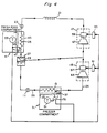
- FIG. 6 a refrigerator having separate evaporator 25 in the fresh food compartment 31 and a separate evaporator 13 in the freezer compartment 31 is shown.
- the thermostatic controller 51 in the freezer compartment is connected to the motor controllers of the hermetically sealed compressors (not shown) and to fans 37 and 47 in the freezer and fresh food compartments, respectively.
- the thermostatic controller 53 is connected to a fan 87 located in one of the two passageways interconnecting the fresh food and freezer compartments.
- Fan 87 can comprise a low energy consumption fan such as a piezoelectric fan.
- thermostatic controller 51 In operation, when thermostatic controller 51 detects the temperature in the freezer has risen above the user selected set point, the compressors (not shown) operate, providing cooled refrigerant in the two evaporators 13 and 25. Fans 37 and 47 circulate air over the evaporators 13 and 25.
- Fan 87 When the fresh food compartment thermostatic controller detects that the temperature in the fresh food compartment is above the desired user selected temperature fan 87 operates circulating air between the compartments cooling the fresh food compartment while warming the freezer compartment. Fan 87 operates whenever the fresh food compartment is above a preselected temperature, whether or not the compressors are operating.
- the compressors shown do not have to be intercooled in order for the controls provided to regulate freezer and fresh food compartment temperature.
- Other intercooling techniques such as shown in copending application EP 89122896.7 can alternatively be used.
- the control shown in Figures 3 and 4 do not require a two stage compressor only two evaporators one operating at temperature to cool the freezer compartment and one operating to cool the fresh food compartment.
- the control of Figure 6 does not require two compressors or two evaporators. A single evaporator located in the freezer compartment with the freezer thermostat controlling the single compressor operation is sufficient. The thermostatic control in the fresh food compartment would still be used to operate the fan controlling airflow between the compartments.
- Figures 1, 2 and 3 can be combined with the control strategy of Figure 6 which provides for air circulation between the fresh food and freezer compartments when the fresh food compartment temperature is above a predetermined set point.
- the combination of the air circulation controls with the controls of Figures 1, 2, and 3 would provide improved fresh food compartment temperature regulation.
Landscapes
- Engineering & Computer Science (AREA)
- Physics & Mathematics (AREA)
- Mechanical Engineering (AREA)
- Thermal Sciences (AREA)
- General Engineering & Computer Science (AREA)
- Chemical & Material Sciences (AREA)
- Combustion & Propulsion (AREA)
- Devices That Are Associated With Refrigeration Equipment (AREA)
- Cold Air Circulating Systems And Constructional Details In Refrigerators (AREA)
Applications Claiming Priority (3)
| Application Number | Priority Date | Filing Date | Title |
|---|---|---|---|
| US07/293,034 US4966010A (en) | 1989-01-03 | 1989-01-03 | Apparatus for controlling a dual evaporator, dual fan refrigerator with independent temperature controls |
| US293034 | 1989-01-03 | ||
| EP89123251A EP0377158B1 (fr) | 1989-01-03 | 1989-12-15 | Réfrigérateur à deux évaporateurs et à deux ventilateurs muni de commandes indépendantes de température |
Related Parent Applications (2)
| Application Number | Title | Priority Date | Filing Date |
|---|---|---|---|
| EP89123251A Division EP0377158B1 (fr) | 1989-01-03 | 1989-12-15 | Réfrigérateur à deux évaporateurs et à deux ventilateurs muni de commandes indépendantes de température |
| EP89123251.4 Division | 1989-12-15 |
Publications (3)
| Publication Number | Publication Date |
|---|---|
| EP0558095A2 true EP0558095A2 (fr) | 1993-09-01 |
| EP0558095A3 EP0558095A3 (en) | 1993-10-13 |
| EP0558095B1 EP0558095B1 (fr) | 1996-04-24 |
Family
ID=23127347
Family Applications (3)
| Application Number | Title | Priority Date | Filing Date |
|---|---|---|---|
| EP89123251A Expired - Lifetime EP0377158B1 (fr) | 1989-01-03 | 1989-12-15 | Réfrigérateur à deux évaporateurs et à deux ventilateurs muni de commandes indépendantes de température |
| EP93104590A Expired - Lifetime EP0553892B1 (fr) | 1989-01-03 | 1989-12-15 | Réfrigérateur à deux évaporateurs et à deux ventilateurs muni de commandes indépendantes de température |
| EP93104589A Expired - Lifetime EP0558095B1 (fr) | 1989-01-03 | 1989-12-15 | Dispositif pour la commande d'un réfrigérateur à deux évaporateurs et à deux ventilateurs munis de commandes indépendantes de température |
Family Applications Before (2)
| Application Number | Title | Priority Date | Filing Date |
|---|---|---|---|
| EP89123251A Expired - Lifetime EP0377158B1 (fr) | 1989-01-03 | 1989-12-15 | Réfrigérateur à deux évaporateurs et à deux ventilateurs muni de commandes indépendantes de température |
| EP93104590A Expired - Lifetime EP0553892B1 (fr) | 1989-01-03 | 1989-12-15 | Réfrigérateur à deux évaporateurs et à deux ventilateurs muni de commandes indépendantes de température |
Country Status (4)
| Country | Link |
|---|---|
| US (1) | US4966010A (fr) |
| EP (3) | EP0377158B1 (fr) |
| JP (1) | JP3126363B2 (fr) |
| DE (3) | DE68924839T2 (fr) |
Cited By (2)
| Publication number | Priority date | Publication date | Assignee | Title |
|---|---|---|---|---|
| AU739833B2 (en) * | 1999-12-27 | 2001-10-18 | Samsung Electronics Co., Ltd. | Operation control apparatus for a refrigerator |
| EP2546591A1 (fr) | 2011-07-15 | 2013-01-16 | Whirlpool Corporation | Procédé de congélation rapide d'aliments |
Families Citing this family (26)
| Publication number | Priority date | Publication date | Assignee | Title |
|---|---|---|---|---|
| US5228308A (en) * | 1990-11-09 | 1993-07-20 | General Electric Company | Refrigeration system and refrigerant flow control apparatus therefor |
| US5103650A (en) * | 1991-03-29 | 1992-04-14 | General Electric Company | Refrigeration systems with multiple evaporators |
| US5134859A (en) * | 1991-03-29 | 1992-08-04 | General Electric Company | Excess refrigerant accumulator for multievaporator vapor compression refrigeration cycles |
| US5231848A (en) * | 1991-09-05 | 1993-08-03 | Tecumseh Products Company | Refrigerator cold control |
| US5191776A (en) * | 1991-11-04 | 1993-03-09 | General Electric Company | Household refrigerator with improved circuit |
| US5156016A (en) * | 1992-02-03 | 1992-10-20 | General Electric Company | Pressure controlled switching valve for refrigeration system |
| US5184473A (en) * | 1992-02-10 | 1993-02-09 | General Electric Company | Pressure controlled switching valve for refrigeration system |
| US5355686A (en) * | 1993-08-11 | 1994-10-18 | Micro Weiss Electronics, Inc. | Dual temperature control of refrigerator-freezer |
| US5406805A (en) * | 1993-11-12 | 1995-04-18 | University Of Maryland | Tandem refrigeration system |
| US5471849A (en) * | 1994-11-18 | 1995-12-05 | General Electric Company | Independent compartment temperature control in a household refrigerator using fan interlock |
| US5487277A (en) * | 1994-11-18 | 1996-01-30 | General Electric Company | Independent compartment temperature control in a household refrigerator using interlinked thermostats |
| DE69723835T2 (de) * | 1996-04-11 | 2004-04-22 | Chiquita Brands, Inc., Cincinnati | Reifungsverfharen und-vorrichtung für verderbliche waren in einem temperaturgesteurten raum |
| US6370908B1 (en) | 1996-11-05 | 2002-04-16 | Tes Technology, Inc. | Dual evaporator refrigeration unit and thermal energy storage unit therefore |
| US6405548B1 (en) | 2000-08-11 | 2002-06-18 | General Electric Company | Method and apparatus for adjusting temperature using air flow |
| EP1340949A4 (fr) | 2000-12-08 | 2009-08-12 | Daikin Ind Ltd | Refrigerateur |
| US6401469B1 (en) * | 2001-09-14 | 2002-06-11 | Carrier Corporation | Control unit and method for two-stage reciprocating compressor |
| DE10161306A1 (de) * | 2001-12-13 | 2003-06-26 | Bsh Bosch Siemens Hausgeraete | Kältegerät mit regelbarer Entfeuchtung |
| JP2003207248A (ja) * | 2002-01-15 | 2003-07-25 | Toshiba Corp | 冷蔵庫 |
| US20060016202A1 (en) * | 2004-07-23 | 2006-01-26 | Daniel Lyvers | Refrigerator with system for controlling drawer temperatures |
| CN101124438B (zh) * | 2005-02-18 | 2010-08-04 | 卡里尔公司 | 具有热回收的co2制冷设备 |
| JP2010525294A (ja) * | 2007-04-24 | 2010-07-22 | キャリア コーポレイション | 2系統エコノマイザ回路を備えた冷媒蒸気圧縮システム |
| US8266917B2 (en) * | 2008-08-01 | 2012-09-18 | Thermo King Corporation | Multi temperature control system |
| JP5334554B2 (ja) * | 2008-12-15 | 2013-11-06 | 三菱電機株式会社 | 空気調和装置 |
| KR102034582B1 (ko) * | 2012-07-24 | 2019-11-08 | 엘지전자 주식회사 | 냉동 사이클 및 냉동 사이클을 포함하는 냉장고 |
| US10352308B2 (en) | 2012-12-18 | 2019-07-16 | Emerson Climate Technologies, Inc. | Reciprocating compressor with vapor injection system |
| TR202013573A2 (tr) | 2020-08-27 | 2022-03-21 | Arçeli̇k Anoni̇m Şi̇rketi̇ | Kombi̇ne kondenser i̇çeren soğutucu ci̇haz |
Family Cites Families (20)
| Publication number | Priority date | Publication date | Assignee | Title |
|---|---|---|---|---|
| FR431893A (fr) * | 1911-07-04 | 1911-11-22 | Linde Eismasch Ag | Procédé de régulation de machines frigorifiques à trois ou plusieurs évaporateurs, pour basses températures |
| US2500688A (en) * | 1948-08-24 | 1950-03-14 | Edward P Kellie | Refrigerating apparatus |
| US2672018A (en) * | 1950-11-03 | 1954-03-16 | Gen Motors Corp | Two-temperature refrigerating apparatus |
| US3005321A (en) * | 1959-08-25 | 1961-10-24 | Philco Corp | Multiple temperature refrigerator |
| US3026688A (en) * | 1961-01-23 | 1962-03-27 | Gen Motors Corp | Controls for two-compartment refrigerator |
| US3107502A (en) * | 1961-04-24 | 1963-10-22 | Whirlpool Co | Air circuit means for combined freezer and refrigerator apparatus |
| US3119240A (en) * | 1962-06-19 | 1964-01-28 | Philco Corp | Refrigeration apparatus with defrost means |
| US3360958A (en) * | 1966-01-21 | 1968-01-02 | Trane Co | Multiple compressor lubrication apparatus |
| US3359751A (en) * | 1966-10-14 | 1967-12-26 | Admiral Corp | Two temperature refrigerator |
| US3455119A (en) * | 1968-02-16 | 1969-07-15 | Gen Motors Corp | Plural compartment high humidity domestic refrigerator |
| US3848422A (en) * | 1972-04-27 | 1974-11-19 | Svenska Rotor Maskiner Ab | Refrigeration plants |
| JPS5410557B2 (fr) * | 1972-08-21 | 1979-05-08 | ||
| US4009591A (en) * | 1976-01-02 | 1977-03-01 | General Electric Company | Single evaporator, single fan combination refrigerator with independent temperature controls |
| JPS5710063A (en) * | 1980-06-20 | 1982-01-19 | Hitachi Ltd | Refrigerating plant |
| US4439998A (en) * | 1980-09-04 | 1984-04-03 | General Electric Company | Apparatus and method of controlling air temperature of a two-evaporator refrigeration system |
| JPS58155582U (ja) * | 1982-04-09 | 1983-10-18 | 株式会社東光冷熱エンジニアリング | 検体輸送のための恒温装置 |
| SU1134858A1 (ru) * | 1983-01-24 | 1985-01-15 | Ленинградский Ордена Ленина Политехнический Институт Им.М.И.Калинина | Холодильна установка |
| US4553584A (en) * | 1983-12-07 | 1985-11-19 | Red Owl Stores, Inc. | Refrigeration/air exchanger system maintaining two different temperature compartments |
| GB8511729D0 (en) * | 1985-05-09 | 1985-06-19 | Svenska Rotor Maskiner Ab | Screw rotor compressor |
| JPS62233645A (ja) * | 1986-03-31 | 1987-10-14 | 三菱電機株式会社 | 冷凍サイクル |
-
1989
- 1989-01-03 US US07/293,034 patent/US4966010A/en not_active Expired - Fee Related
- 1989-12-15 EP EP89123251A patent/EP0377158B1/fr not_active Expired - Lifetime
- 1989-12-15 DE DE68924839T patent/DE68924839T2/de not_active Expired - Fee Related
- 1989-12-15 EP EP93104590A patent/EP0553892B1/fr not_active Expired - Lifetime
- 1989-12-15 DE DE68926353T patent/DE68926353T2/de not_active Expired - Fee Related
- 1989-12-15 EP EP93104589A patent/EP0558095B1/fr not_active Expired - Lifetime
- 1989-12-15 DE DE68924857T patent/DE68924857T2/de not_active Expired - Fee Related
-
1990
- 1990-01-04 JP JP02000027A patent/JP3126363B2/ja not_active Expired - Fee Related
Cited By (2)
| Publication number | Priority date | Publication date | Assignee | Title |
|---|---|---|---|---|
| AU739833B2 (en) * | 1999-12-27 | 2001-10-18 | Samsung Electronics Co., Ltd. | Operation control apparatus for a refrigerator |
| EP2546591A1 (fr) | 2011-07-15 | 2013-01-16 | Whirlpool Corporation | Procédé de congélation rapide d'aliments |
Also Published As
| Publication number | Publication date |
|---|---|
| EP0558095B1 (fr) | 1996-04-24 |
| EP0553892A3 (en) | 1993-10-13 |
| JPH0317484A (ja) | 1991-01-25 |
| EP0553892B1 (fr) | 1995-11-15 |
| EP0558095A3 (en) | 1993-10-13 |
| DE68926353D1 (de) | 1996-05-30 |
| DE68924857D1 (de) | 1995-12-21 |
| EP0377158A3 (fr) | 1991-07-24 |
| EP0553892A2 (fr) | 1993-08-04 |
| JP3126363B2 (ja) | 2001-01-22 |
| US4966010A (en) | 1990-10-30 |
| DE68924839D1 (de) | 1995-12-21 |
| DE68926353T2 (de) | 1996-12-12 |
| EP0377158B1 (fr) | 1995-11-15 |
| DE68924839T2 (de) | 1996-07-18 |
| EP0377158A2 (fr) | 1990-07-11 |
| DE68924857T2 (de) | 1996-07-18 |
Similar Documents
| Publication | Publication Date | Title |
|---|---|---|
| US4966010A (en) | Apparatus for controlling a dual evaporator, dual fan refrigerator with independent temperature controls | |
| US5220806A (en) | Apparatus for controlling a dual evaporator, dual fan refrigerator with independent temperature controls | |
| US5056328A (en) | Apparatus for controlling a dual evaporator, dual fan refrigerator with independent temperature controls | |
| US9714786B2 (en) | Cooling system with increased efficiency | |
| KR0160436B1 (ko) | 고효율 독립냉각 싸이클을 가지는 냉장고 및 그 제어방법 | |
| US5150583A (en) | Apparatus for controlling a dual evaporator, dual fan refrigerator with independent temperature controls | |
| CN106482441B (zh) | 制冷设备工作方法以及制冷设备 | |
| US20150276306A1 (en) | Synchronous temperature rate control and apparatus for refrigeration with reduced energy consumption | |
| US9140477B2 (en) | Synchronous compartment temperature control and apparatus for refrigeration with reduced energy consumption | |
| CA2409539A1 (fr) | Methodes et dispositif de commande de la vitesse de rotation d'un compresseur | |
| CN106524647B (zh) | 一种冰箱的控制方法 | |
| JP2000230766A (ja) | 冷却サイクル及び冷蔵庫 | |
| US5109678A (en) | Apparatus for controlling a dual evaporator, dual fan refrigerator with independent temperature controls | |
| JPH08210753A (ja) | 高効率独立冷却サイクル(High efficiency Multi−evaporatorcycle:H.M.CYCLE)を持つ冷蔵庫の運転制御回路及びその運転制御方法 | |
| WO2021223530A1 (fr) | Procédé de commande pour climatiseur à onduleur | |
| KR100189100B1 (ko) | 고효율 독립냉각 싸이클을 가지는 냉장고의 제어방법 | |
| JPH11148761A (ja) | 冷蔵庫 | |
| WO1999042772A1 (fr) | Circuit de regulation de mode thermique pour differentes temperatures | |
| KR100772233B1 (ko) | 냉장고 및 냉장고의 제어 방법 | |
| JP3710353B2 (ja) | 冷蔵庫 | |
| CN119164147B (zh) | 一种冰箱及控制方法 | |
| JPH0989435A (ja) | 冷凍冷蔵庫 | |
| CN109883104A (zh) | 冰箱及其控制方法 | |
| JP2002286347A (ja) | 冷却貯蔵庫 | |
| JPS63243671A (ja) | 冷凍装置 |
Legal Events
| Date | Code | Title | Description |
|---|---|---|---|
| PUAI | Public reference made under article 153(3) epc to a published international application that has entered the european phase |
Free format text: ORIGINAL CODE: 0009012 |
|
| PUAL | Search report despatched |
Free format text: ORIGINAL CODE: 0009013 |
|
| 17P | Request for examination filed |
Effective date: 19930320 |
|
| AC | Divisional application: reference to earlier application |
Ref document number: 377158 Country of ref document: EP |
|
| AK | Designated contracting states |
Kind code of ref document: A2 Designated state(s): DE FR GB IT |
|
| AK | Designated contracting states |
Kind code of ref document: A3 Designated state(s): DE FR GB IT |
|
| 17Q | First examination report despatched |
Effective date: 19940620 |
|
| GRAH | Despatch of communication of intention to grant a patent |
Free format text: ORIGINAL CODE: EPIDOS IGRA |
|
| GRAA | (expected) grant |
Free format text: ORIGINAL CODE: 0009210 |
|
| AC | Divisional application: reference to earlier application |
Ref document number: 377158 Country of ref document: EP |
|
| AK | Designated contracting states |
Kind code of ref document: B1 Designated state(s): DE FR GB IT |
|
| ET | Fr: translation filed | ||
| REF | Corresponds to: |
Ref document number: 68926353 Country of ref document: DE Date of ref document: 19960530 |
|
| ITF | It: translation for a ep patent filed | ||
| PLBE | No opposition filed within time limit |
Free format text: ORIGINAL CODE: 0009261 |
|
| 26N | No opposition filed | ||
| PGFP | Annual fee paid to national office [announced via postgrant information from national office to epo] |
Ref country code: FR Payment date: 20011120 Year of fee payment: 13 |
|
| PGFP | Annual fee paid to national office [announced via postgrant information from national office to epo] |
Ref country code: GB Payment date: 20011122 Year of fee payment: 13 |
|
| PGFP | Annual fee paid to national office [announced via postgrant information from national office to epo] |
Ref country code: DE Payment date: 20011123 Year of fee payment: 13 |
|
| REG | Reference to a national code |
Ref country code: GB Ref legal event code: IF02 |
|
| PG25 | Lapsed in a contracting state [announced via postgrant information from national office to epo] |
Ref country code: GB Free format text: LAPSE BECAUSE OF NON-PAYMENT OF DUE FEES Effective date: 20021215 |
|
| PG25 | Lapsed in a contracting state [announced via postgrant information from national office to epo] |
Ref country code: DE Free format text: LAPSE BECAUSE OF NON-PAYMENT OF DUE FEES Effective date: 20030701 |
|
| GBPC | Gb: european patent ceased through non-payment of renewal fee |
Effective date: 20021215 |
|
| PG25 | Lapsed in a contracting state [announced via postgrant information from national office to epo] |
Ref country code: FR Free format text: LAPSE BECAUSE OF NON-PAYMENT OF DUE FEES Effective date: 20030901 |
|
| REG | Reference to a national code |
Ref country code: FR Ref legal event code: ST |
|
| PG25 | Lapsed in a contracting state [announced via postgrant information from national office to epo] |
Ref country code: IT Free format text: LAPSE BECAUSE OF NON-PAYMENT OF DUE FEES;WARNING: LAPSES OF ITALIAN PATENTS WITH EFFECTIVE DATE BEFORE 2007 MAY HAVE OCCURRED AT ANY TIME BEFORE 2007. THE CORRECT EFFECTIVE DATE MAY BE DIFFERENT FROM THE ONE RECORDED. Effective date: 20051215 |