EP0558353A2 - Commande d'énergie optimale pour défibrillateurs implantables - Google Patents
Commande d'énergie optimale pour défibrillateurs implantables Download PDFInfo
- Publication number
- EP0558353A2 EP0558353A2 EP93301513A EP93301513A EP0558353A2 EP 0558353 A2 EP0558353 A2 EP 0558353A2 EP 93301513 A EP93301513 A EP 93301513A EP 93301513 A EP93301513 A EP 93301513A EP 0558353 A2 EP0558353 A2 EP 0558353A2
- Authority
- EP
- European Patent Office
- Prior art keywords
- current
- pulse
- defibrillation
- voltage
- electrode
- Prior art date
- Legal status (The legal status is an assumption and is not a legal conclusion. Google has not performed a legal analysis and makes no representation as to the accuracy of the status listed.)
- Granted
Links
Images



Classifications
-
- A—HUMAN NECESSITIES
- A61—MEDICAL OR VETERINARY SCIENCE; HYGIENE
- A61N—ELECTROTHERAPY; MAGNETOTHERAPY; RADIATION THERAPY; ULTRASOUND THERAPY
- A61N1/00—Electrotherapy; Circuits therefor
- A61N1/18—Applying electric currents by contact electrodes
- A61N1/32—Applying electric currents by contact electrodes alternating or intermittent currents
- A61N1/38—Applying electric currents by contact electrodes alternating or intermittent currents for producing shock effects
- A61N1/39—Heart defibrillators
- A61N1/3925—Monitoring; Protecting
-
- A—HUMAN NECESSITIES
- A61—MEDICAL OR VETERINARY SCIENCE; HYGIENE
- A61N—ELECTROTHERAPY; MAGNETOTHERAPY; RADIATION THERAPY; ULTRASOUND THERAPY
- A61N1/00—Electrotherapy; Circuits therefor
- A61N1/18—Applying electric currents by contact electrodes
- A61N1/32—Applying electric currents by contact electrodes alternating or intermittent currents
- A61N1/38—Applying electric currents by contact electrodes alternating or intermittent currents for producing shock effects
- A61N1/39—Heart defibrillators
- A61N1/3956—Implantable devices for applying electric shocks to the heart, e.g. for cardioversion
-
- A—HUMAN NECESSITIES
- A61—MEDICAL OR VETERINARY SCIENCE; HYGIENE
- A61N—ELECTROTHERAPY; MAGNETOTHERAPY; RADIATION THERAPY; ULTRASOUND THERAPY
- A61N1/00—Electrotherapy; Circuits therefor
- A61N1/18—Applying electric currents by contact electrodes
- A61N1/32—Applying electric currents by contact electrodes alternating or intermittent currents
- A61N1/38—Applying electric currents by contact electrodes alternating or intermittent currents for producing shock effects
- A61N1/39—Heart defibrillators
- A61N1/3906—Heart defibrillators characterised by the form of the shockwave
-
- A—HUMAN NECESSITIES
- A61—MEDICAL OR VETERINARY SCIENCE; HYGIENE
- A61N—ELECTROTHERAPY; MAGNETOTHERAPY; RADIATION THERAPY; ULTRASOUND THERAPY
- A61N1/00—Electrotherapy; Circuits therefor
- A61N1/18—Applying electric currents by contact electrodes
- A61N1/32—Applying electric currents by contact electrodes alternating or intermittent currents
- A61N1/38—Applying electric currents by contact electrodes alternating or intermittent currents for producing shock effects
- A61N1/39—Heart defibrillators
- A61N1/3906—Heart defibrillators characterised by the form of the shockwave
- A61N1/3912—Output circuitry therefor, e.g. switches
Definitions
- the present invention relates generally to defibrillation methods, and more particularly, to implantable defibrillation systems for optimizing the efficiency thereof by steering energy and current.
- the high values of current that are employed generally in defibrillation procedures and the compactness that is essential in implantable systems are conflicting requirements. For this reason, a huge premium is placed on optimal delivery of the current and energy necessary for successful defibrillation. But, with the kinds of defibrillation electrodes that are most conveniently employed, the energy distribution or "steering that occurs naturally departs significantly from the optimum.
- the present invention provides steering methods that improve the pattern of energy delivery when the simplest and least costly electrode systems are used.
- capacitor-discharge systems are almost universally used in defibrillation. Achieving the requisite electric field needed to depolarize most of the myocardial cells requires current density above a certain threshold value, and via Ohm's law, this means the process is favored by achieving sufficiently low electrical resistance in the discharge path. For this reason, the use of electrodes of relatively large surface area has for a long time been the norm. [A. C. Guyton and J. Satterfield, "Factors Concerned in Defibrillation of the Heart, Particularly through the Unopened Chest", Am. J. of Physiology , Vol. 167, p.
- FIG. 1B J.C. Schuder, et al., "Transthoracic Ventricular Defibrillation in the Dog with truncated and Untruncated Exponential Stimuli", IEEE Trans Biom. Eng. , Vol. BME-18, p. 410, November, 1971.] That is, the capacitor discharge is simply interrupted by opening a switch at some middle point, typically, approximately at the time that the characteristic RC time" has been reached. The advent of compact solidstate switches has made such pulse tailoring a straightforward matter.
- the truncated capacitance discharge pulse shown in FIG.1 is known as the monophasic waveform of the prior art.
- An important variation on the pulse shape is the biphasic waveform of FIG. 1C, wherein the pulse is extended, but with reversed polarity, again through a switching technique.
- epicardial-patch electrodes 46 and 47 which are relatively large-area flexible conductive elements that are stitched directly to the epicardium, or exterior of the heart 49, as illustrated in FIG. 2.
- epicardial-patch electrodes 46 and 47 are relatively large-area flexible conductive elements that are stitched directly to the epicardium, or exterior of the heart 49, as illustrated in FIG. 2.
- the obvious shortcoming of this method is, of course, that it requires major surgery and invokes the hazards of opening the chest cavity for attachment of the patches.
- An appreciably simpler option positions an endocardial coil electrode 62 at the right ventricular apex (RVA) 64, or the lowest point inside the right ventricle 66.
- RVA right ventricular apex
- This option usually takes the form of a helix or coil, fabricated from metal, ribbon or wire, wound on the exterior of a cardiac catheter 60 that is introduced intravenously.
- This option is illustrated in the lower-left hand portion of FIG. 3. Since the catheter can be used for other purposes, such as pacing, as well, the simple addition of an electrode to it is an attractive feature of this option. Even more important, the surgery needed for the use of epicardial patches is avoided. And since it is ventricular tissue that requires electrical treatment for successful defibrillation, such an RVA electrode 62 is quite strategically positioned for the purpose.
- a second electrode is also needed, of course, to accompany the RVA electrode.
- An option that is often used is the subcutaneous patch 54 (hereinafter abbreviated as (“SUB"). It is a relatively large-area element, illustrated schematically in the lower-right portion of FIG. 3 (where distances are not represented to scale), that is positioned under the skin of the left chest. Thus, current passed from SUB 54 to RVA 62 intersects virtually all of the ventricular tissue, as desired.
- the SUB 54 option has the shortcoming that the patch, as a shallow implant, is vulnerable to damage from bumps and other mishaps, and even from normal bodily motion, but it has the major advantage that open-chest surgery is again avoided.
- a promising alternative (for augmentation) to the SUB electrode is using the metal housing or CAN 52 (as hereinafter designated) of the defibrillation pulse-generator module 57 as an electrode, an option that is the subject of a co-pending application.
- CAN 52 is mechanically stronger than SUB 54, and hence is not liable to breakage, and also because CAN 52 must be implanted in any case.
- the CAN option is illustrated schematically in the upper-right portion of FIG. 3.
- a fourth electrode option that is comparatively easy to realize is simply a second endocardial coil added to a catheter that already carries the RVA electrode.
- SVC superior vena cava 70
- the right atrium itself is sometimes chosen as the location, and an appreciably more difficult-to-reach location, the coronary sinus, is also sometimes chosen. But since these three sites are proximate, we shall simplify the following descriptions by using the SVC designation only to stand for any electrode in this region of the heart.
- FIG. 3 shows the relationships of all four of these electrodes that are comparatively easy to implant. It is evident, now, that several choices of electrode interconnections and polarities exist for applying the defibrillation waveform.
- the top-down current is not as effective as an equal "horizontal" current would be, one passing through much of the ventricular myocardium.
- the SVC electrode typically makes a small-area contact with the cardiac tissue, and the resulting locally high value of current density can cause tissue damage.
- Evidence of the first assertion is the observation that the three-electrode option is at best marginally more effective for defibrillation than the two-electrode option, RVA and SUB only.
- a CAN electrode of the co-pending application may be used in lieu of SUB, and that this would yield a comparable physical and electrical situation. Note, however, that combining CAN and SUB in parallel will produce an improvement by reducing resistance in the "horizontal " pathway, thereby rendering the vertical and horizontal currents more nearly equal. But it is still desirable, whether one or two left-chest electrodes are used, to diminish the wasted current and energy in the SVC-RVA pathway, to reduce tissue damage at the same time, and still to retain whatever defibrillation benefit can be derived from the diminished current in this path, since the SVC electrode is available at small incremental cost.
- the duration of the SVC waveform might be 40% to 60% that of the SUB waveform.
- This arrangement will cause a major fraction of the discharge energy to flow from SUB to RVA, and an example of the resulting monophasic waveform is illustrated in FIG. 5A.
- the characteristic time (RC time) of the system is cut in half by placing SUB and SVC in parallel, with the resulting factor-of-two change of slope in the waveform that is displayed in FIG. 5A.
- this arrangement automatically reduces peak voltage, and hence peak current and peak field in the tissue, in the path of the briefer pulse, which is displayed in FIG. 5B.
- the smaller-duration waveform could be shifted to an earlier time, in the limit having the same peak voltage as the waveform applied to SUB.
- Such variations are produced by altering the operation timing of switches 96 and 100 in FIG. 4.
- the duration of a defibrillating pulse is another variable that is not related linearly to pulse effectiveness, with pulses of 2 to 3 milliseconds having been shown to be useful. This relates to a characteristic time of the heart known as chronaxie.
- chronaxie a characteristic time of the heart known as chronaxie.
- pulse duration is only one of several methods for altering energy distribution between two discharge paths, or among more than two. It is also possible to reduce the voltage delivered to one electrode as compared to another. (Let us adhere to the case of three electrodes, RVA 62, SVC 68, and SUB 54, since this case fully illustrates the principles.) A simple way to achieve this result is by placing a lossy element in series in the path where lower voltage and current are desired.
- the voltage amplitude is 0.707 of the initial value, so that the energy remains in the capacitor is half that initially stored.
- Each resistor dissipates one-quarter of the initial energy, which is to say that 6.125J is delivered to the defibrillation path.
- Another lossy-device option is the "current limiter”.
- This term usually identifies a two-terminal current-regulating device of a kind that has been known in the semiconductor art since the latter 1950s. From the early 1950s it has been possible to accomplish a similar result by using three-terminal devices, and hence somewhat more complicated circuitry.
- the simplest realization of a two-terminal current limiter is a depletion-mode field-effect transistor, either JFET or MOSFET, with source and drain being the two relevant terminals.
- Field-effect transistors with characteristic currents above an ampere have been fabricated since the 1960s, and are useful as switches in the defibrillation art.
- FIG. 7A The current-voltage characteristic of a current limiter is shown in FIG. 7A.
- FIG. 7B the current-limiter I-V characteristic is idealized somewhat and superimposed on that of the defibrillation path, taken to be the 70-ohm fixed resistor R. Placing the defibrillation path and current limiter in series yields the composite I-V characteristic presented in FIG. 7C.
- the accompanying voltage waveform is shown as the lower trace in FIG. 7E, while the voltage waveform on R and cement limiter in series is the upper trace.
- the current-limiter method delivers 65% as much energy to the defibrillation path as does a conventional monophasic waveform generated without lossy elements.
- the reason for this good performance is that the grossly nonlinear current limiter "looks like" a small and declining resistance to the capacitor, with an effective value for the case of the idealized current limiter that goes from 48 ohms to zero during the course of the particular pulse of the example.
- the resistor R3 matching defibrillation-path resistance R permits 33% as much energy to be delivered to the defibrillation path as does the monophasic pulse of equal duration.
- the capacitance-switching method delivers 25% of the energy delivered by the monophasic pulse.
- the current-limiter method is applicable to the biphasic option as well as the monophasic.
- a JFET with floating gate displays the I-V characteristic shown in FIG. 7F, and hence constitutes a bilaterally symmetric current limiter.
- One significant aspect and feature of the present invention is the full use of electrodes that can be implanted by means of comparatively low-cost and low-risk methods, with examples being RVA, SVC, SUB, and CAN electrodes.
- Another significant aspect and feature of the present invention is the steering of the energy of a defibrillation pulse to achieve a more favorable energy distribution than occurs naturally when such convenient electrodes are used.
- Still another significant aspect and feature of the present invention is the steering of the current of a defibrillation pulse to achieve a more favorable current distribution than occurs naturally when such convenient electrodes are used.
- Yet another significant aspect and feature of the present invention is the use of SUB and CAN electrodes in common to reduce the resistance in the resulting defibrillation pathway as compared to just one of the pathways.
- Another significant aspect and feature of the present invention is the use of a lossy device in the SVC-RVA pathway to reduce current and energy therein.
- Still another significant aspect and feature of the present invention is the use of a resistor in the SVC-RVA pathway to reduce current and energy therein.
- Yet another significant aspect and feature of the present invention is the use of a current limiter in the SVC-RVA pathway to reduce current and energy therein.
- Another significant aspect and feature of the present invention is the use of a smaller-duration pulse in the SVC-RVA pathway than in the SUB-RVA pathway or the CAN-RVA pathway, to reduce current and energy in the first pathway.
- Still another significant aspect and feature of the present invention is using one or more current limiters in one or more defibrillation pathways to derive from a capacitor discharge rectangular current and voltage pulses in thorn pathways.
- a further object of the present invention is the steering of the energy of a defibrillation pulse to achieve a more favorable energy distribution than occurs naturally when the most convenient electrodes are used.
- a still further object of the present invention is the steering of the current of a defibrillation pulse to achieve a more favorable current distribution than occurs naturally when the most convenient electrodes are used.
- Still another object of the present invention is to use the SUB and CAN electrodes in common to reduce the resistance in the resulting defibrillation pathway as compared to just one of the pathways.
- a further object of the present invention is to reduce current and energy in the SVC-RVA pathway as compared to those values in other pathways.
- a still further object of the present invention is to diminish tissue damage in the SVC-RVA pathway.
- Yet a further object of the present invention is to derive from a capacitor discharge rectangular current and voltage pulses in one or more defibrillation pathways.
- a still further object of the present invention is to improve the efficiency of an implantable defibrillation system.
- Yet a further object of the present invention is to diminish the size of the pulse generator for an implantable defibrillation system having a given degree of defibrillation effectiveness.
- a further object of the present invention is facilitating the pectoral implantation of the pulse generator for an implantable defibrillation system having a given degree of defibrillation effectiveness, in turn to permit taking advantage of the CAN electrode.
- FIG. 1A illustrates the voltage-time waveform 10 of a capacitor discharged through a resistor, and waveform displaying the characteristic time 12 known as the RC time.
- FIG. 1B illustrates the voltage-time waveform 20 of a monophasic pulse of the prior art, produced by discharging a capacitor through a resistor and terminating the pulse after a time 22 by switching.
- FIG. 1C illustrates the voltage-time waveform 30 of a biphasic pulse of the prior art, produced by discharging a capacitor through a resistor, reversing the polarity by switching after a time interval 32, and terminating the pulse after a further time interval 34 by further switching.
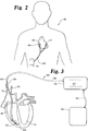
- FIG. 2 illustrates schematically a patient 40 fitted with a defibrillation system comprising an abdominally implanted pulse generator 42, connected by means of electrical harness 44 to two epicardial-patch electrodes 46 and 47, which are attached to the heart 49 of the patient 40.
- FIG. 3 illustrates schematically and for purposes of illustration a defibrillation system 50 including a pectorally implanted pulse generator 57 serving as a CAN electrode 52, the pulse generator 57 attached to a subcutaneously implanted SUB electrode 54 by interconnection 56, and by interconnection 58 to a cardiac catheter 60 that includes a first endocardial-coil electrode 62 positioned at the apex 64 of the right ventricle 66, the coil being the RVA electrode 62, and a second endocardial-coil electrode 68 positioned in the superior vena cava 70, which is above the right atrium 72, the second coil being the SVC electrode 68, a configuration that causes defibrillation current coming from the CAN electrode 52 and coming from the SUB electrode 54 substantially to intersect the left ventricle 74, as well as the right ventricle 66.
- the methods of the present invention reduce defibrillation current and energy delivered to the path from the SVC electrode 68 to the RVA electrode 62
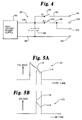
- FIG. 4 illustrates schematically a pulse-generator configuration 80 for an implantable defibrillation system, the configuration comprising a high-voltage power supply 82, having first and second output leads 84 and 86 for charging a capacitor 88, the capacitor to be discharged through at least one of two paths, where the first path 90 is completed through chest tissue form an SVC electrode 68 that is connected to a first terminal 92, to an RVA electrode 62 that is connected to a second terminal 94 that is in turn connected to the second output lead 86, the first path 90 being under the control of a first single-pole, single-throw switch 96, and where the second path 98 is under the control of a second single-pole, single-throw switch 100, and where said second path 98 is completed through chest tissue from electrically common SUB and CAN electrodes 54 and 52 that are respectively connected to a third terminal 102 and a fourth terminal 104, again to the RVA electrode 62 that is connected to the second terminal 94 with the present invention adjusting the current
- FIG. 5A illustrates the voltage-time waveform 110 of a monophasic pulse produced by discharging a capacitor through one or more paths initially, and placing an additional path in parallel therewith during the course of the pulse at the time 112, and terminating current through all paths simultaneously by switching at the time 114.
- FIG. 5B illustrates the voltage-time waveform 120 received by the additional path in the description of FIG. 5A, a waveform that results from closing the switches in the additional path at the time 112, and terminating current through the path at the time 114 where all numerals correspond to those elements previously described.
- FIG. 5C illustrates the voltage-time waveform 130 of a biphasic pulse, produced by the method in the description of FIG. 5A, but with the addition of polarity reversal by switching at the time 114 in lieu of pulse termination, of again placing the additional path in parallel with the primary path at the time 136 during the cows of the reversed-polarity pulse, and then terminating current through all paths simultaneously by switching at time 138 where all numerals correspond to those elements previously described.
- FIG. 5D illustrates the voltage-time waveform received by the additional path in the description of FIG. 5C, wherein the additional path is placed in parallel with the primary path at the time 136 during the course of the reversed-polarity pulse, and then current through all paths is terminated simultaneously by switching at time 138 where all numerals correspond to those elements previously described.
- FIG. 6A illustrates the voltage-time waveform 150 of a particular monophasic pulse for analytic comparison, comprising an initial voltage 152, a final voltage 154, and a pulse duration 156 where all numerals correspond to those elements previously described.
- FIG. 6B illustrates the voltage-time waveform 160 of a monophasic pulse produced by capacitor switching, comprising an initial voltage 162, a final voltage 164, and a pulse duration 166 where all numerals correspond to those elements previously described.
- FIG. 6C illustrates the voltage-time waveform 170 produced by doubling the resistance used in the case of FIG. 6A, the waveform 170 having a pulse duration 172, and comprising an upper trace 174 representing voltage on the two resistors in series, and having an initial voltage 176, a final voltage 178, and having a lower trace 180 representing voltage on the tissue resistor, and having an initial voltage 182, a final voltage 184 where all numerals correspond to those elements previously described.
- FIG. 7A illustrates the current-voltage characteristic of a current limiter, having a characteristic current 192.
- FIG. 7B illustrates a comparison 200 of an idealized current-voltage characteristic 202 for a particular current limiter with a characteristic current 204 superimposed upon current-voltage characteristic 206 of a resistor of 70 ohms where all numerals correspond to those elements previously described.
- FIG. 7C illustrates the composite current-voltage characteristic 210 of the particular idealized current limiter 202 of FIG. 7B placed in series with the particular 70-ohm resistor 206 of FIG. 7B, displaying a "knee" 212 with coordinates 5.91A and 413.6V where all numerals correspond to those elements previously described.
- FIG.7D illustrates the rectangular current-time waveform 220 of a particular monophasic pulse having an amplitude 222 and a pulse duration 224, achieved by using a current limiter, where all numerals correspond to those elements previously described.
- FIG. 7E illustrates a voltage-time waveform 230 of a particular monophasic pulse achieved by using a current limiter, with the lower trace 232 representing the rectangular voltage-time waveform delivered to the defibrillation path, having an amplitude 234 and a pulse duration 235, and having an upper trace 236 with an initial amplitude 238 where all numerals correspond to those elements previously described.
- FIG.7F illustrates the current-voltage characteristic 240 of a bilaterally symmetric current limiters, specifically a floating-gate JFET, having a characteristic-current magnitude 242 in either polarity where all numerals correspond to those elements previously described.
- the defibrillation electrodes whose implantation is least costly and risky to a patient are somewhat less efficient than those attached directly to the heart exterior.
- Examples in the former category are endocardial coils, positioned on the exterior of a cardiac catheter that is introduced transvenously into the interior of the heart.
- RVA right-ventricular-apex
- other positional options for an endocardial coil are inside the right atrium, or inside the coronary sinus, or inside the superior vena cava (SVC). These last three positions are comparatively close together in the heart, and are for convenience here lumped and labeled "SVC".
- the present invention improves the performance of these easier-to-implant electrodes by modifying the pattern of energy and current delivery that occurs naturally when two or more defibrillation-current pathways are created by means of these four or six electrode options.
- the natural pattern is determined by the respective path resistances.
- Modifications of the pattern not only yields more efficient defibrillation, but also diminishes tissue damage resulting from excessive current in low-resistance paths.
- the modification is achieved in the invention by, for example, assigning to a lower-resistance path a (1) smaller pulse duration, or (2) a lower-voltage capacitor discharge.
- the second method comprises the options of capacitor switching or of introducing a lossy element in series in such a path or paths. Particularly advantageous is the use of a current limiter as the lossy element, because it is capable of generating a pulse of rectangular waveform, a technique useful for both single-path and multiple-path situations.
- Such a pulse delivers a maximum of energy for a given peak-field value with a particular electrode combination and pulse duration. Peak field is a measure of the tissue-damage potentiality of a particular discharge.
Landscapes
- Health & Medical Sciences (AREA)
- Cardiology (AREA)
- Heart & Thoracic Surgery (AREA)
- Engineering & Computer Science (AREA)
- Biomedical Technology (AREA)
- Nuclear Medicine, Radiotherapy & Molecular Imaging (AREA)
- Radiology & Medical Imaging (AREA)
- Life Sciences & Earth Sciences (AREA)
- Animal Behavior & Ethology (AREA)
- General Health & Medical Sciences (AREA)
- Public Health (AREA)
- Veterinary Medicine (AREA)
- Electrotherapy Devices (AREA)
Applications Claiming Priority (2)
| Application Number | Priority Date | Filing Date | Title |
|---|---|---|---|
| US07/841,544 US5306291A (en) | 1992-02-26 | 1992-02-26 | Optimal energy steering for an implantable defibrillator |
| US841544 | 1997-04-23 |
Publications (3)
| Publication Number | Publication Date |
|---|---|
| EP0558353A2 true EP0558353A2 (fr) | 1993-09-01 |
| EP0558353A3 EP0558353A3 (en) | 1995-02-22 |
| EP0558353B1 EP0558353B1 (fr) | 1998-10-21 |
Family
ID=25285146
Family Applications (1)
| Application Number | Title | Priority Date | Filing Date |
|---|---|---|---|
| EP93301513A Expired - Lifetime EP0558353B1 (fr) | 1992-02-26 | 1993-02-26 | Commande d'énergie optimale pour défibrillateurs implantables |
Country Status (3)
| Country | Link |
|---|---|
| US (4) | US5306291A (fr) |
| EP (1) | EP0558353B1 (fr) |
| DE (1) | DE69321629T2 (fr) |
Cited By (11)
| Publication number | Priority date | Publication date | Assignee | Title |
|---|---|---|---|---|
| EP0739224A4 (fr) * | 1993-12-13 | 1998-02-25 | Angeion Corp | Defibrillateur implantable a condensateurs a couches polymeres minces |
| US5824018A (en) * | 1992-09-25 | 1998-10-20 | Cardiac Pacemakers, Inc. | Fibrillation induction method and system for implantable devices |
| US6016442A (en) * | 1998-03-25 | 2000-01-18 | Cardiac Pacemakers, Inc. | System for displaying cardiac arrhythmia data |
| US6453201B1 (en) | 1999-10-20 | 2002-09-17 | Cardiac Pacemakers, Inc. | Implantable medical device with voice responding and recording capacity |
| EP1535645A1 (fr) * | 1996-12-18 | 2005-06-01 | Zmd Corporation | Forme de courant pour électrothérapie |
| WO2005092437A1 (fr) * | 2004-03-19 | 2005-10-06 | Medtronic, Inc. | Procede et appareil destines a administrer des formes d'ondes de defibrillation multidirectionnelles |
| US6983185B2 (en) | 1998-07-22 | 2006-01-03 | Cardiac Pacemakers, Inc. | Lead with terminal connector assembly |
| US6987998B2 (en) | 2001-02-28 | 2006-01-17 | Cardiac Pacemakers, Inc. | Cardiac rhythm management patient report |
| US7047065B2 (en) | 2000-12-15 | 2006-05-16 | Cardiac Pacemakers, Inc. | System and method for correlation of patient health information and implant device data |
| US7751892B2 (en) | 2003-05-07 | 2010-07-06 | Cardiac Pacemakers, Inc. | Implantable medical device programming apparatus having a graphical user interface |
| US9949687B2 (en) | 2000-12-15 | 2018-04-24 | Cardiac Pacemakers, Inc. | System and method for correlation of patient health information and device data |
Families Citing this family (154)
| Publication number | Priority date | Publication date | Assignee | Title |
|---|---|---|---|---|
| US5713926A (en) | 1990-04-25 | 1998-02-03 | Cardiac Pacemakers, Inc. | Implantable intravenous cardiac stimulation system with pulse generator housing serving as optional additional electrode |
| US5306291A (en) * | 1992-02-26 | 1994-04-26 | Angeion Corporation | Optimal energy steering for an implantable defibrillator |
| US5470346A (en) * | 1992-03-18 | 1995-11-28 | Angeion Corporation | Connector ports for an implantable defibrillator |
| US5522853A (en) * | 1992-10-27 | 1996-06-04 | Angeion Corporation | Method and apparatus for progressive recruitment of cardiac fibrillation |
| US5441518A (en) * | 1993-07-22 | 1995-08-15 | Angeion Corporation | Implantable cardioverter defibrillator system having independently controllable electrode discharge pathway |
| US5674248A (en) * | 1995-01-23 | 1997-10-07 | Angeion Corporation | Staged energy concentration for an implantable biomedical device |
| US5620464A (en) * | 1992-12-18 | 1997-04-15 | Angeion Corporation | System and method for delivering multiple closely spaced defibrillation pulses |
| US5601612A (en) * | 1993-08-06 | 1997-02-11 | Heartstream, Inc. | Method for applying a multiphasic waveform |
| US5607454A (en) * | 1993-08-06 | 1997-03-04 | Heartstream, Inc. | Electrotherapy method and apparatus |
| US5620465A (en) * | 1995-06-08 | 1997-04-15 | Survivalink Corporation | External defibrillator for producing and testing biphasic waveforms |
| US5620467A (en) * | 1995-10-10 | 1997-04-15 | Incontrol, Inc. | Implantable atrial defibrillator having cardioverting output voltage limiting for simulating larger storage capacitors |
| US5645572A (en) * | 1996-03-12 | 1997-07-08 | Angeion Corporation | Implantable cardioverter defibrillator with slew rate limiting |
| US5690686A (en) * | 1996-04-30 | 1997-11-25 | Medtronic, Inc. | Atrial defibrillation method |
| US5733309A (en) * | 1996-05-13 | 1998-03-31 | Kroll; Mark W. | Method and apparatus for capacitive switching output for implantable cardioverter defibrillator |
| US5800465A (en) * | 1996-06-18 | 1998-09-01 | Medtronic, Inc. | System and method for multisite steering of cardiac stimuli |
| US5968080A (en) * | 1996-07-01 | 1999-10-19 | Survivalink Corporation | Method for determining the second phase of external defibrillator devices |
| US6411846B1 (en) | 1999-08-26 | 2002-06-25 | Survivalink Corporation | Method and apparatus for delivering a biphasic defibrillation pulse with variable energy |
| US6263239B1 (en) | 1996-07-01 | 2001-07-17 | Survivalink Corporation | Method and apparatus for determining the second phase of defibrillator devices |
| US5733310A (en) * | 1996-12-18 | 1998-03-31 | Zmd Corporation | Electrotherapy circuit and method for producing therapeutic discharge waveform immediately following sensing pulse |
| US5797968A (en) * | 1996-12-18 | 1998-08-25 | Zmd Corporation | Electrotherapy circuit for producing current waveform with sawtooth ripple |
| US5800463A (en) * | 1996-12-18 | 1998-09-01 | Zmd Corporation | Electrotherapy circuit having controlled peak current |
| US6096063A (en) * | 1996-12-18 | 2000-08-01 | Zmd Corporation | Electrotherapy circuit having controlled current discharge based on patient-dependent electrical parameter |
| US5769872A (en) * | 1996-12-18 | 1998-06-23 | Zmd Corporation | Electrotherapy circuit and method for shaping current waveforms |
| US5800462A (en) * | 1996-12-18 | 1998-09-01 | Zmd Corporation | Electrotherapy circuit for producing therapeutic discharge waveform based on high-current sensing pulse |
| US5904706A (en) * | 1996-12-18 | 1999-05-18 | Zmd Corporation | Method and apparatus for producing electrotherapy current waveform with ripple |
| US6963773B2 (en) * | 1997-03-05 | 2005-11-08 | Medtronic Physio-Control Manufacturing Corp. | H-bridge circuit for generating a high-energy biphasic waveform in an external defibrillator using single SCR and IGBT switches in an integrated package |
| US5792189A (en) * | 1997-04-04 | 1998-08-11 | The Research Foundation Of State University Of New York | Defibrillation utilizing the dominant frequency of fibrillation |
| US6067471A (en) | 1998-08-07 | 2000-05-23 | Cardiac Pacemakers, Inc. | Atrial and ventricular implantable cardioverter-defibrillator and lead system |
| US5849031A (en) * | 1997-12-16 | 1998-12-15 | Medtronic, Inc. | Method and apparatus for termination of tachyarrhythmias |
| US6173204B1 (en) | 1998-10-13 | 2001-01-09 | Physio-Control Manufacturing Corporation | Semiconductor assisted relay in a biphasic defibrillator |
| US6208895B1 (en) * | 1998-10-13 | 2001-03-27 | Physio-Control Manufacturing Corporation | Circuit for performing external pacing and biphasic defibrillation |
| US8244370B2 (en) * | 2001-04-13 | 2012-08-14 | Greatbatch Ltd. | Band stop filter employing a capacitor and an inductor tank circuit to enhance MRI compatibility of active medical devices |
| US6208896B1 (en) | 1998-11-13 | 2001-03-27 | Agilent Technologies, Inc. | Method and apparatus for providing variable defibrillation waveforms using switch-mode amplification |
| US6241751B1 (en) | 1999-04-22 | 2001-06-05 | Agilent Technologies, Inc. | Defibrillator with impedance-compensated energy delivery |
| US6405081B1 (en) * | 1999-04-22 | 2002-06-11 | Koninklijke Philips Electronics N.V. | Damped biphasic energy delivery circuit for a defibrillator |
| US6418340B1 (en) | 1999-08-20 | 2002-07-09 | Cardiac Pacemakers, Inc. | Method and system for identifying and displaying groups of cardiac arrhythmic episodes |
| US6721594B2 (en) | 1999-08-24 | 2004-04-13 | Cardiac Pacemakers, Inc. | Arrythmia display |
| DE19945179C2 (de) * | 1999-09-21 | 2001-11-15 | Siemens Ag | Verfahren zur Vorgabe einer Rampe durch eine getaktete Größe |
| US7346392B2 (en) * | 2000-09-12 | 2008-03-18 | Uab Research Foundation | Method and apparatus for the monitoring and treatment of spontaneous cardiac arrhythmias |
| US6988003B2 (en) * | 2000-09-18 | 2006-01-17 | Cameron Health, Inc. | Implantable cardioverter-defibrillator having two spaced apart shocking electrodes on housing |
| US7751885B2 (en) * | 2000-09-18 | 2010-07-06 | Cameron Health, Inc. | Bradycardia pacing in a subcutaneous device |
| US7039465B2 (en) * | 2000-09-18 | 2006-05-02 | Cameron Health, Inc. | Ceramics and/or other material insulated shell for active and non-active S-ICD can |
| US6937907B2 (en) * | 2000-09-18 | 2005-08-30 | Cameron Health, Inc. | Subcutaneous electrode for transthoracic conduction with low-profile installation appendage and method of doing same |
| US7146212B2 (en) * | 2000-09-18 | 2006-12-05 | Cameron Health, Inc. | Anti-bradycardia pacing for a subcutaneous implantable cardioverter-defibrillator |
| US20020035381A1 (en) * | 2000-09-18 | 2002-03-21 | Cameron Health, Inc. | Subcutaneous electrode with improved contact shape for transthoracic conduction |
| US6927721B2 (en) * | 2001-11-05 | 2005-08-09 | Cameron Health, Inc. | Low power A/D converter |
| US7092754B2 (en) * | 2000-09-18 | 2006-08-15 | Cameron Health, Inc. | Monophasic waveform for anti-bradycardia pacing for a subcutaneous implantable cardioverter-defibrillator |
| US7194302B2 (en) * | 2000-09-18 | 2007-03-20 | Cameron Health, Inc. | Subcutaneous cardiac stimulator with small contact surface electrodes |
| US6952608B2 (en) * | 2001-11-05 | 2005-10-04 | Cameron Health, Inc. | Defibrillation pacing circuitry |
| US7076296B2 (en) * | 2000-09-18 | 2006-07-11 | Cameron Health, Inc. | Method of supplying energy to subcutaneous cardioverter-defibrillator and pacer |
| US7043299B2 (en) * | 2000-09-18 | 2006-05-09 | Cameron Health, Inc. | Subcutaneous implantable cardioverter-defibrillator employing a telescoping lead |
| US6834204B2 (en) | 2001-11-05 | 2004-12-21 | Cameron Health, Inc. | Method and apparatus for inducing defibrillation in a patient using a T-shock waveform |
| US7194309B2 (en) * | 2000-09-18 | 2007-03-20 | Cameron Health, Inc. | Packaging technology for non-transvenous cardioverter/defibrillator devices |
| US6856835B2 (en) * | 2000-09-18 | 2005-02-15 | Cameron Health, Inc. | Biphasic waveform for anti-tachycardia pacing for a subcutaneous implantable cardioverter-defibrillator |
| US7090682B2 (en) | 2000-09-18 | 2006-08-15 | Cameron Health, Inc. | Method and apparatus for extraction of a subcutaneous electrode |
| US6754528B2 (en) * | 2001-11-21 | 2004-06-22 | Cameraon Health, Inc. | Apparatus and method of arrhythmia detection in a subcutaneous implantable cardioverter/defibrillator |
| US20020035378A1 (en) * | 2000-09-18 | 2002-03-21 | Cameron Health, Inc. | Subcutaneous electrode for transthoracic conduction with highly maneuverable insertion tool |
| US6866044B2 (en) | 2000-09-18 | 2005-03-15 | Cameron Health, Inc. | Method of insertion and implantation of implantable cardioverter-defibrillator canisters |
| US7069080B2 (en) * | 2000-09-18 | 2006-06-27 | Cameron Health, Inc. | Active housing and subcutaneous electrode cardioversion/defibrillating system |
| US7120495B2 (en) * | 2000-09-18 | 2006-10-10 | Cameron Health, Inc. | Flexible subcutaneous implantable cardioverter-defibrillator |
| US6788974B2 (en) * | 2000-09-18 | 2004-09-07 | Cameron Health, Inc. | Radian curve shaped implantable cardioverter-defibrillator canister |
| US6952610B2 (en) * | 2000-09-18 | 2005-10-04 | Cameron Health, Inc. | Current waveforms for anti-tachycardia pacing for a subcutaneous implantable cardioverter- defibrillator |
| US20020035379A1 (en) | 2000-09-18 | 2002-03-21 | Bardy Gust H. | Subcutaneous electrode for transthoracic conduction with improved installation characteristics |
| US6950705B2 (en) | 2000-09-18 | 2005-09-27 | Cameron Health, Inc. | Canister designs for implantable cardioverter-defibrillators |
| US7149575B2 (en) * | 2000-09-18 | 2006-12-12 | Cameron Health, Inc. | Subcutaneous cardiac stimulator device having an anteriorly positioned electrode |
| US6778860B2 (en) | 2001-11-05 | 2004-08-17 | Cameron Health, Inc. | Switched capacitor defibrillation circuit |
| US20020107544A1 (en) * | 2000-09-18 | 2002-08-08 | Cameron Health, Inc. | Current waveform for anti-bradycardia pacing for a subcutaneous implantable cardioverter-defibrillator |
| US6865417B2 (en) * | 2001-11-05 | 2005-03-08 | Cameron Health, Inc. | H-bridge with sensing circuit |
| US6954670B2 (en) * | 2001-11-05 | 2005-10-11 | Cameron Health, Inc. | Simplified defibrillator output circuit |
| US6721597B1 (en) | 2000-09-18 | 2004-04-13 | Cameron Health, Inc. | Subcutaneous only implantable cardioverter defibrillator and optional pacer |
| US20020035377A1 (en) * | 2000-09-18 | 2002-03-21 | Cameron Health, Inc. | Subcutaneous electrode for transthoracic conduction with insertion tool |
| WO2002083016A1 (fr) | 2001-04-13 | 2002-10-24 | Surgi-Vision, Inc. | Systemes et procedes d'interventions guidees par resonance magnetique |
| US9295828B2 (en) | 2001-04-13 | 2016-03-29 | Greatbatch Ltd. | Self-resonant inductor wound portion of an implantable lead for enhanced MRI compatibility of active implantable medical devices |
| US6567698B2 (en) | 2001-07-17 | 2003-05-20 | Koninklijke Philips Electronics N.V. | System and method for applying sequential low energy defibrillation pulses |
| CA2459049A1 (fr) * | 2001-08-31 | 2003-03-13 | Access Cardiosystems, Inc. | Systeme de defibrillateur externe automatique (dea) |
| US7248921B2 (en) | 2003-06-02 | 2007-07-24 | Cameron Health, Inc. | Method and devices for performing cardiac waveform appraisal |
| US7330757B2 (en) * | 2001-11-21 | 2008-02-12 | Cameron Health, Inc. | Method for discriminating between ventricular and supraventricular arrhythmias |
| US7392085B2 (en) * | 2001-11-21 | 2008-06-24 | Cameron Health, Inc. | Multiple electrode vectors for implantable cardiac treatment devices |
| US6965796B2 (en) * | 2002-03-11 | 2005-11-15 | Medtronic Physio-Control Manufacturing Corp. | Method and apparatus for self-test of defibrillation and pacing circuits including a patient isolation switch |
| US7096062B2 (en) * | 2002-03-11 | 2006-08-22 | Medtronic Physio-Control Manufacturing Corp. | Method for self-test of defibrillation and pacing circuits including a patient isolation switch |
| US20050038474A1 (en) * | 2002-04-30 | 2005-02-17 | Wool Thomas J. | Implantable automatic defibrillator with subcutaneous electrodes |
| US6968230B2 (en) | 2002-06-26 | 2005-11-22 | Medtronic Physio-Control Manufacturing Corp | H-bridge circuit for generating a high-energy biphasic and external pacing waveform in an external defibrillator |
| US20040044371A1 (en) * | 2002-09-04 | 2004-03-04 | Medtronic Physio-Control Manufacturing Corp. | Defibrillator with H-bridge output circuit referenced to common ground |
| US6909915B2 (en) * | 2003-01-24 | 2005-06-21 | Gentcorp Ltd. | Hybrid battery power source for implantable medical use |
| US7136701B2 (en) * | 2003-01-24 | 2006-11-14 | Gentcorp Ltd. | Hybrid battery power source for implantable medical use |
| US7020519B2 (en) * | 2003-01-24 | 2006-03-28 | Gentcorp Ltd | Hybrid battery power source for implantable medical use |
| US20040199082A1 (en) * | 2003-04-03 | 2004-10-07 | Ostroff Alan H. | Selctable notch filter circuits |
| US8239045B2 (en) * | 2003-06-04 | 2012-08-07 | Synecor Llc | Device and method for retaining a medical device within a vessel |
| US7082336B2 (en) | 2003-06-04 | 2006-07-25 | Synecor, Llc | Implantable intravascular device for defibrillation and/or pacing |
| AU2004251673B2 (en) | 2003-06-04 | 2010-01-28 | Synecor Llc | Intravascular electrophysiological system and methods |
| US7617007B2 (en) * | 2003-06-04 | 2009-11-10 | Synecor Llc | Method and apparatus for retaining medical implants within body vessels |
| US20050107833A1 (en) * | 2003-11-13 | 2005-05-19 | Freeman Gary A. | Multi-path transthoracic defibrillation and cardioversion |
| EP1701766A2 (fr) * | 2003-12-12 | 2006-09-20 | Synecor, LLC | Dispositif medical implantable possedant un exosquelette de pre-implantation |
| JP4680939B2 (ja) * | 2004-02-10 | 2011-05-11 | シネコー・エルエルシー | 治療薬用脈管内送達システム |
| KR100601953B1 (ko) * | 2004-05-03 | 2006-07-14 | 삼성전자주식회사 | 메모리 소자의 캐패시터 및 그 제조 방법 |
| US20060089681A1 (en) * | 2004-10-21 | 2006-04-27 | Cameron Health, Inc. | Implantable medical device |
| US8175702B2 (en) | 2004-11-04 | 2012-05-08 | The Washington University | Method for low-voltage termination of cardiac arrhythmias by effectively unpinning anatomical reentries |
| US7477935B2 (en) * | 2004-11-29 | 2009-01-13 | Cameron Health, Inc. | Method and apparatus for beat alignment and comparison |
| US7376458B2 (en) * | 2004-11-29 | 2008-05-20 | Cameron Health, Inc. | Method for defining signal templates in implantable cardiac devices |
| US7655014B2 (en) * | 2004-12-06 | 2010-02-02 | Cameron Health, Inc. | Apparatus and method for subcutaneous electrode insertion |
| US8229563B2 (en) * | 2005-01-25 | 2012-07-24 | Cameron Health, Inc. | Devices for adapting charge initiation for an implantable cardioverter-defibrillator |
| US8160697B2 (en) | 2005-01-25 | 2012-04-17 | Cameron Health, Inc. | Method for adapting charge initiation for an implantable cardioverter-defibrillator |
| US7555338B2 (en) * | 2005-04-26 | 2009-06-30 | Cameron Health, Inc. | Methods and implantable devices for inducing fibrillation by alternating constant current |
| US8116867B2 (en) * | 2005-08-04 | 2012-02-14 | Cameron Health, Inc. | Methods and devices for tachyarrhythmia sensing and high-pass filter bypass |
| US7457662B2 (en) * | 2005-09-09 | 2008-11-25 | Cardiac Science Corporation | Method and apparatus for variable capacitance defibrillation |
| US8046060B2 (en) | 2005-11-14 | 2011-10-25 | Cardiac Pacemakers, Inc. | Differentiating arrhythmic events having different origins |
| US7623909B2 (en) | 2006-05-26 | 2009-11-24 | Cameron Health, Inc. | Implantable medical devices and programmers adapted for sensing vector selection |
| US20070276452A1 (en) * | 2006-05-26 | 2007-11-29 | Cameron Health, Inc. | Implantable medical device systems having initialization functions and methods of operation |
| US7783340B2 (en) | 2007-01-16 | 2010-08-24 | Cameron Health, Inc. | Systems and methods for sensing vector selection in an implantable medical device using a polynomial approach |
| US8200341B2 (en) | 2007-02-07 | 2012-06-12 | Cameron Health, Inc. | Sensing vector selection in a cardiac stimulus device with postural assessment |
| US8788023B2 (en) | 2006-05-26 | 2014-07-22 | Cameron Health, Inc. | Systems and methods for sensing vector selection in an implantable medical device |
| US20080015644A1 (en) * | 2006-07-14 | 2008-01-17 | Cameron Health, Inc. | End of life battery testing in an implantable medical device |
| US8718793B2 (en) | 2006-08-01 | 2014-05-06 | Cameron Health, Inc. | Electrode insertion tools, lead assemblies, kits and methods for placement of cardiac device electrodes |
| US7623913B2 (en) | 2006-08-01 | 2009-11-24 | Cameron Health, Inc. | Implantable medical devices using heuristic filtering in cardiac event detection |
| US8154853B2 (en) * | 2006-08-03 | 2012-04-10 | Cardiac Pacemakers, Inc. | Method and apparatus for partitioned capacitor |
| US8170662B2 (en) * | 2006-08-03 | 2012-05-01 | Cardiac Pacemakers, Inc. | Method and apparatus for charging partitioned capacitors |
| US8761875B2 (en) * | 2006-08-03 | 2014-06-24 | Cardiac Pacemakers, Inc. | Method and apparatus for selectable energy storage partitioned capacitor |
| US7877139B2 (en) | 2006-09-22 | 2011-01-25 | Cameron Health, Inc. | Method and device for implantable cardiac stimulus device lead impedance measurement |
| US8014851B2 (en) * | 2006-09-26 | 2011-09-06 | Cameron Health, Inc. | Signal analysis in implantable cardiac treatment devices |
| CA2673971C (fr) | 2006-11-13 | 2016-07-19 | Washington University Of St. Louis | Stimulation cardiaque utilisant une extension nodale inferieure |
| US7623916B2 (en) | 2006-12-20 | 2009-11-24 | Cameron Health, Inc. | Implantable cardiac stimulus devices and methods with input recharge circuitry |
| US8874208B2 (en) | 2007-12-11 | 2014-10-28 | The Washington University | Methods and devices for three-stage ventricular therapy |
| AU2008335087B2 (en) * | 2007-12-11 | 2013-10-24 | Washington University Of St. Louis | Method and device for low-energy termination of atrial tachyarrhythmias |
| US8560066B2 (en) | 2007-12-11 | 2013-10-15 | Washington University | Method and device for three-stage atrial cardioversion therapy |
| US8244349B2 (en) * | 2008-02-02 | 2012-08-14 | Cameron Health, Inc. | Adaptive shock delivery in an implantable cardiac stimulus device |
| US10080889B2 (en) | 2009-03-19 | 2018-09-25 | Greatbatch Ltd. | Low inductance and low resistance hermetically sealed filtered feedthrough for an AIMD |
| US9108066B2 (en) | 2008-03-20 | 2015-08-18 | Greatbatch Ltd. | Low impedance oxide resistant grounded capacitor for an AIMD |
| US20110015713A1 (en) * | 2008-10-23 | 2011-01-20 | Pacesetter, Inc. | Systems and methods for reducing lead heating and the risks of mri-induced stimulation |
| US20100106227A1 (en) * | 2008-10-23 | 2010-04-29 | Pacesetter, Inc. | Systems and Methods for Disconnecting Electrodes of Leads of Implantable Medical Devices During an MRI to Reduce Lead Heating |
| US8301249B2 (en) * | 2008-10-23 | 2012-10-30 | Pacesetter, Inc. | Systems and methods for exploiting the tip or ring conductor of an implantable medical device lead during an MRI to reduce lead heating and the risks of MRI-induced stimulation |
| US8473051B1 (en) | 2010-12-29 | 2013-06-25 | Cardialen, Inc. | Low-energy atrial cardioversion therapy with controllable pulse-shaped waveforms |
| US9427596B2 (en) | 2013-01-16 | 2016-08-30 | Greatbatch Ltd. | Low impedance oxide resistant grounded capacitor for an AIMD |
| US11198014B2 (en) | 2011-03-01 | 2021-12-14 | Greatbatch Ltd. | Hermetically sealed filtered feedthrough assembly having a capacitor with an oxide resistant electrical connection to an active implantable medical device housing |
| US10350421B2 (en) | 2013-06-30 | 2019-07-16 | Greatbatch Ltd. | Metallurgically bonded gold pocket pad for grounding an EMI filter to a hermetic terminal for an active implantable medical device |
| US9931514B2 (en) | 2013-06-30 | 2018-04-03 | Greatbatch Ltd. | Low impedance oxide resistant grounded capacitor for an AIMD |
| US10272252B2 (en) | 2016-11-08 | 2019-04-30 | Greatbatch Ltd. | Hermetic terminal for an AIMD having a composite brazed conductive lead |
| US10596369B2 (en) | 2011-03-01 | 2020-03-24 | Greatbatch Ltd. | Low equivalent series resistance RF filter for an active implantable medical device |
| US9126055B2 (en) | 2012-04-20 | 2015-09-08 | Cardiac Science Corporation | AED faster time to shock method and device |
| US9295850B2 (en) * | 2012-04-24 | 2016-03-29 | Medtronic, Inc. | Charge-balancing during electrical stimulation |
| US10905884B2 (en) | 2012-07-20 | 2021-02-02 | Cardialen, Inc. | Multi-stage atrial cardioversion therapy leads |
| US8868178B2 (en) | 2012-12-11 | 2014-10-21 | Galvani, Ltd. | Arrhythmia electrotherapy device and method with provisions for mitigating patient discomfort |
| USRE46699E1 (en) | 2013-01-16 | 2018-02-06 | Greatbatch Ltd. | Low impedance oxide resistant grounded capacitor for an AIMD |
| US9149645B2 (en) | 2013-03-11 | 2015-10-06 | Cameron Health, Inc. | Methods and devices implementing dual criteria for arrhythmia detection |
| US9579065B2 (en) | 2013-03-12 | 2017-02-28 | Cameron Health Inc. | Cardiac signal vector selection with monophasic and biphasic shape consideration |
| EP3741424B1 (fr) | 2014-02-24 | 2022-05-04 | Element Science, Inc. | Défibrillateur externe |
| EP4678105A3 (fr) | 2015-08-26 | 2026-04-01 | Element Science, Inc. | Dispositifs de défibrillation portables |
| US11318310B1 (en) | 2015-10-26 | 2022-05-03 | Nevro Corp. | Neuromodulation for altering autonomic functions, and associated systems and methods |
| US10249415B2 (en) | 2017-01-06 | 2019-04-02 | Greatbatch Ltd. | Process for manufacturing a leadless feedthrough for an active implantable medical device |
| US10912945B2 (en) | 2018-03-22 | 2021-02-09 | Greatbatch Ltd. | Hermetic terminal for an active implantable medical device having a feedthrough capacitor partially overhanging a ferrule for high effective capacitance area |
| US10905888B2 (en) | 2018-03-22 | 2021-02-02 | Greatbatch Ltd. | Electrical connection for an AIMD EMI filter utilizing an anisotropic conductive layer |
| CN112839585A (zh) | 2018-10-10 | 2021-05-25 | 元素科学公司 | 具有一次性部件和可重新使用部件的可穿戴式装置 |
| US11590352B2 (en) | 2019-01-29 | 2023-02-28 | Nevro Corp. | Ramped therapeutic signals for modulating inhibitory interneurons, and associated systems and methods |
| EP3772361A1 (fr) * | 2019-08-06 | 2021-02-10 | BIOTRONIK SE & Co. KG | Générateur d'impulsions pouvant être implanté à ondes rectangulaires |
| US12558547B2 (en) | 2021-05-25 | 2026-02-24 | Nevro Corp. | Modified high frequency neuromodulation signals, and associated systems and methods |
Family Cites Families (38)
| Publication number | Priority date | Publication date | Assignee | Title |
|---|---|---|---|---|
| US3236239A (en) * | 1962-07-17 | 1966-02-22 | American Optical Corp | Defibrillator |
| US3389704A (en) * | 1965-12-06 | 1968-06-25 | Zenith Radio Corp | Discharge circuit for a defibrillator |
| US3942536A (en) * | 1971-03-15 | 1976-03-09 | Mieczyslaw Mirowski | Cardioverting device having single intravascular catheter electrode system and method for its use |
| US3886950A (en) * | 1973-10-01 | 1975-06-03 | Spacelabs Inc | Defibrillator |
| US4014347A (en) * | 1975-05-27 | 1977-03-29 | Staodynamics, Inc. | Transcutaneous nerve stimulator device and method |
| US4168711A (en) * | 1978-06-08 | 1979-09-25 | American Optical Corporation | Reversal protection for RLC defibrillator |
| US4708145A (en) * | 1982-06-01 | 1987-11-24 | Medtronic, Inc. | Sequential-pulse, multiple pathway defibrillation method |
| US4548203A (en) * | 1982-06-01 | 1985-10-22 | Purdue Research Foundation | Sequential-pulse, multiple pathway defibrillation method |
| US4499907A (en) * | 1982-11-15 | 1985-02-19 | Medtronic, Inc. | Energy limiting cardioversion lead |
| US4727877A (en) * | 1984-12-18 | 1988-03-01 | Medtronic, Inc. | Method and apparatus for low energy endocardial defibrillation |
| US5111811A (en) * | 1985-06-20 | 1992-05-12 | Medtronic, Inc. | Cardioversion and defibrillation lead system with electrode extension into the coronary sinus and great vein |
| US4662377A (en) * | 1985-11-07 | 1987-05-05 | Mieczyslaw Mirowski | Cardioverting method and apparatus utilizing catheter and patch electrodes |
| US4800883A (en) * | 1986-04-02 | 1989-01-31 | Intermedics, Inc. | Apparatus for generating multiphasic defibrillation pulse waveform |
| US4953551A (en) * | 1987-01-14 | 1990-09-04 | Medtronic, Inc. | Method of defibrillating a heart |
| CA1308170C (fr) * | 1987-01-14 | 1992-09-29 | Rahul Mehra | Appareil de defibrillation cardiaque |
| US4821723A (en) * | 1987-02-27 | 1989-04-18 | Intermedics Inc. | Biphasic waveforms for defibrillation |
| US4944300A (en) * | 1987-04-28 | 1990-07-31 | Sanjeev Saksena | Method for high energy defibrillation of ventricular fibrillation in humans without a thoracotomy |
| US4817608A (en) * | 1987-05-29 | 1989-04-04 | Mieczyslaw Mirowski | Cardioverting transvenous catheter/patch electrode system and method for its use |
| EP0326290B1 (fr) * | 1988-01-19 | 1995-12-27 | Telectronics N.V. | Procédé et appareil d'application de chocs opposés asymétriques biphasés tronqués exponentiels |
| US5083562A (en) * | 1988-01-19 | 1992-01-28 | Telectronics Pacing Systems, Inc. | Method and apparatus for applying asymmetric biphasic truncated exponential countershocks |
| US4811156A (en) * | 1988-02-26 | 1989-03-07 | Cherne Medical, Inc. | Medical current limiter |
| US4964406A (en) * | 1989-05-19 | 1990-10-23 | Ventritex, Inc. | Implantable cardiac defibrillator employing a switched capacitor stage having a non-50/50 duty cycle |
| US4969463A (en) * | 1989-06-06 | 1990-11-13 | Cardiac Pacemakers, Inc. | Defibrillation electrode and method for employing gatling discharge defibrillation |
| US5007422A (en) * | 1989-06-06 | 1991-04-16 | Ventritex, Inc. | Method for combiner cardiac pacing and defibrillation |
| US4998531A (en) * | 1990-03-28 | 1991-03-12 | Cardiac Pacemakers, Inc. | Implantable N-phasic defibrillator output bridge circuit |
| US5133353A (en) * | 1990-04-25 | 1992-07-28 | Cardiac Pacemakers, Inc. | Implantable intravenous cardiac stimulation system with pulse generator housing serving as optional additional electrode |
| US5050601A (en) * | 1990-05-29 | 1991-09-24 | Joel Kupersmith | Cardiac defibrillator electrode arrangement |
| US5163427A (en) * | 1990-11-14 | 1992-11-17 | Medtronic, Inc. | Apparatus for delivering single and multiple cardioversion and defibrillation pulses |
| US5107834A (en) * | 1991-01-30 | 1992-04-28 | Cardiac Pacemakers, Inc. | Low energy multiple shock defibrillation/cardioversion discharge technique and electrode configuration |
| US5131388A (en) * | 1991-03-14 | 1992-07-21 | Ventritex, Inc. | Implantable cardiac defibrillator with improved capacitors |
| US5209229A (en) * | 1991-05-20 | 1993-05-11 | Telectronics Pacing Systems, Inc. | Apparatus and method employing plural electrode configurations for cardioversion of atrial fibrillation in an arrhythmia control system |
| US5199429A (en) * | 1991-05-23 | 1993-04-06 | Angemed, Inc. | Implantable defibrillator system employing capacitor switching networks |
| US5261400A (en) * | 1992-02-12 | 1993-11-16 | Medtronic, Inc. | Defibrillator employing transvenous and subcutaneous electrodes and method of use |
| US5306291A (en) * | 1992-02-26 | 1994-04-26 | Angeion Corporation | Optimal energy steering for an implantable defibrillator |
| US5385575A (en) * | 1992-03-24 | 1995-01-31 | Angeion Corporation | Implantable cardioverter defibrillator having variable output capacitance |
| US5366484A (en) * | 1992-04-09 | 1994-11-22 | Angeion Corporation | Short-pulse cardioversion system for an implantable cardioverter defibrillator |
| EP0574609B1 (fr) * | 1992-06-17 | 1998-12-02 | Pacesetter AB | Defibrillateur/cardioverteur |
| US5324309A (en) * | 1992-09-25 | 1994-06-28 | Medtronic, Inc. | Overlapping pulse cardioversion or defibrillation |
-
1992
- 1992-02-26 US US07/841,544 patent/US5306291A/en not_active Expired - Lifetime
-
1993
- 1993-02-26 EP EP93301513A patent/EP0558353B1/fr not_active Expired - Lifetime
- 1993-02-26 DE DE69321629T patent/DE69321629T2/de not_active Expired - Fee Related
- 1993-07-22 US US08/096,009 patent/US5413591A/en not_active Expired - Fee Related
-
1994
- 1994-04-22 US US08/231,036 patent/US5514160A/en not_active Expired - Lifetime
-
1995
- 1995-12-22 US US08/577,949 patent/US5735878A/en not_active Expired - Fee Related
Cited By (15)
| Publication number | Priority date | Publication date | Assignee | Title |
|---|---|---|---|---|
| US5824018A (en) * | 1992-09-25 | 1998-10-20 | Cardiac Pacemakers, Inc. | Fibrillation induction method and system for implantable devices |
| EP0739224A4 (fr) * | 1993-12-13 | 1998-02-25 | Angeion Corp | Defibrillateur implantable a condensateurs a couches polymeres minces |
| EP1535645A1 (fr) * | 1996-12-18 | 2005-06-01 | Zmd Corporation | Forme de courant pour électrothérapie |
| US6016442A (en) * | 1998-03-25 | 2000-01-18 | Cardiac Pacemakers, Inc. | System for displaying cardiac arrhythmia data |
| US6091990A (en) * | 1998-03-25 | 2000-07-18 | Cardiac Pacemakers, Inc. | System for grouping and displaying cardiac arrhythmia data |
| US6253102B1 (en) | 1998-03-25 | 2001-06-26 | Cardiac Pacemakers, Inc. | System for displaying cardiac arrhythmia data |
| US6301503B1 (en) | 1998-03-25 | 2001-10-09 | Cardiac Pacemakers, Inc. | System for grouping and displaying cardiac arrhythmia data |
| US6983185B2 (en) | 1998-07-22 | 2006-01-03 | Cardiac Pacemakers, Inc. | Lead with terminal connector assembly |
| US6453201B1 (en) | 1999-10-20 | 2002-09-17 | Cardiac Pacemakers, Inc. | Implantable medical device with voice responding and recording capacity |
| US6865424B2 (en) | 1999-10-20 | 2005-03-08 | Cardiac Pacemakers, Inc. | Implantable medical device with voice responding and recording capacity |
| US7047065B2 (en) | 2000-12-15 | 2006-05-16 | Cardiac Pacemakers, Inc. | System and method for correlation of patient health information and implant device data |
| US9949687B2 (en) | 2000-12-15 | 2018-04-24 | Cardiac Pacemakers, Inc. | System and method for correlation of patient health information and device data |
| US6987998B2 (en) | 2001-02-28 | 2006-01-17 | Cardiac Pacemakers, Inc. | Cardiac rhythm management patient report |
| US7751892B2 (en) | 2003-05-07 | 2010-07-06 | Cardiac Pacemakers, Inc. | Implantable medical device programming apparatus having a graphical user interface |
| WO2005092437A1 (fr) * | 2004-03-19 | 2005-10-06 | Medtronic, Inc. | Procede et appareil destines a administrer des formes d'ondes de defibrillation multidirectionnelles |
Also Published As
| Publication number | Publication date |
|---|---|
| US5413591A (en) | 1995-05-09 |
| US5735878A (en) | 1998-04-07 |
| EP0558353B1 (fr) | 1998-10-21 |
| DE69321629D1 (de) | 1998-11-26 |
| US5514160A (en) | 1996-05-07 |
| DE69321629T2 (de) | 1999-06-17 |
| EP0558353A3 (en) | 1995-02-22 |
| US5306291A (en) | 1994-04-26 |
Similar Documents
| Publication | Publication Date | Title |
|---|---|---|
| EP0558353B1 (fr) | Commande d'énergie optimale pour défibrillateurs implantables | |
| US5324309A (en) | Overlapping pulse cardioversion or defibrillation | |
| US4953551A (en) | Method of defibrillating a heart | |
| EP0281219B1 (fr) | Défibrillateur cardiaque | |
| US5545183A (en) | Method and apparatus for delivering defibrillation therapy through a sensing electrode | |
| EP0515059B1 (fr) | Système implantable de défibrillation | |
| EP0540266B1 (fr) | Appareil de traitement préliminaire à une défibrillation cardiaque | |
| US6128531A (en) | Delivery of ICD shock capacitor energy via a controlled current source | |
| EP0757578B1 (fr) | Appareil de production de chocs anti-arythmie equilibres en charge | |
| US5083562A (en) | Method and apparatus for applying asymmetric biphasic truncated exponential countershocks | |
| JP4312830B2 (ja) | 植込形パルス・ジェネレータ及び植込形体組織刺激装置 | |
| US6233483B1 (en) | System and method for generating a high efficiency biphasic defibrillation waveform for use in an implantable cardioverter/defibrillator (ICD). | |
| US5507781A (en) | Implantable defibrillator system with capacitor switching circuitry | |
| US5766226A (en) | Switched discharge pathways for ICD having multiple output capacitors | |
| US6668193B2 (en) | Method and apparatus for cardiac shock therapy | |
| WO2000027465A1 (fr) | Circuit de sortie pour la regulation cardiaque | |
| EP2092953A2 (fr) | Sonde de stimulation implantable à utiliser avec un dispositif ICD disposant de fonctions de stimulation avec capture automatique | |
| US20010031992A1 (en) | System and method of generating a high efficiency biphasic defibrillation waveform for use in an implantable cardioverter/defibrillator (ICD) | |
| WO1997038753A1 (fr) | Ondes pour defibrillation externe | |
| EP0326290A1 (fr) | Procédé et appareil d'application de chocs opposés asymétriques biphasés tronqués exponentiels | |
| JP2025175036A (ja) | 矩形衝撃波形の植込型パルス発生器 | |
| US5411526A (en) | Improved implantable defibrillator system for producing true-voltage-pulse waveforms | |
| SK285835B6 (sk) | Spôsob riadenia činnosti kardiostimulátora na elektrickú stimuláciu srdca | |
| Block et al. | Optimizing defibrillation through improved waveforms | |
| US5733309A (en) | Method and apparatus for capacitive switching output for implantable cardioverter defibrillator |
Legal Events
| Date | Code | Title | Description |
|---|---|---|---|
| PUAI | Public reference made under article 153(3) epc to a published international application that has entered the european phase |
Free format text: ORIGINAL CODE: 0009012 |
|
| AK | Designated contracting states |
Kind code of ref document: A2 Designated state(s): DE GB NL |
|
| PUAL | Search report despatched |
Free format text: ORIGINAL CODE: 0009013 |
|
| AK | Designated contracting states |
Kind code of ref document: A3 Designated state(s): DE GB NL |
|
| 17P | Request for examination filed |
Effective date: 19950605 |
|
| 17Q | First examination report despatched |
Effective date: 19960503 |
|
| RAP1 | Party data changed (applicant data changed or rights of an application transferred) |
Owner name: ANGEION CORPORATION |
|
| GRAG | Despatch of communication of intention to grant |
Free format text: ORIGINAL CODE: EPIDOS AGRA |
|
| GRAG | Despatch of communication of intention to grant |
Free format text: ORIGINAL CODE: EPIDOS AGRA |
|
| GRAH | Despatch of communication of intention to grant a patent |
Free format text: ORIGINAL CODE: EPIDOS IGRA |
|
| GRAH | Despatch of communication of intention to grant a patent |
Free format text: ORIGINAL CODE: EPIDOS IGRA |
|
| GRAA | (expected) grant |
Free format text: ORIGINAL CODE: 0009210 |
|
| AK | Designated contracting states |
Kind code of ref document: B1 Designated state(s): DE GB NL |
|
| PG25 | Lapsed in a contracting state [announced via postgrant information from national office to epo] |
Ref country code: NL Free format text: LAPSE BECAUSE OF FAILURE TO SUBMIT A TRANSLATION OF THE DESCRIPTION OR TO PAY THE FEE WITHIN THE PRESCRIBED TIME-LIMIT Effective date: 19981021 |
|
| REF | Corresponds to: |
Ref document number: 69321629 Country of ref document: DE Date of ref document: 19981126 |
|
| NLV1 | Nl: lapsed or annulled due to failure to fulfill the requirements of art. 29p and 29m of the patents act | ||
| PLBE | No opposition filed within time limit |
Free format text: ORIGINAL CODE: 0009261 |
|
| STAA | Information on the status of an ep patent application or granted ep patent |
Free format text: STATUS: NO OPPOSITION FILED WITHIN TIME LIMIT |
|
| 26N | No opposition filed | ||
| PGFP | Annual fee paid to national office [announced via postgrant information from national office to epo] |
Ref country code: DE Payment date: 19991231 Year of fee payment: 8 |
|
| PGFP | Annual fee paid to national office [announced via postgrant information from national office to epo] |
Ref country code: GB Payment date: 20000223 Year of fee payment: 8 |
|
| PG25 | Lapsed in a contracting state [announced via postgrant information from national office to epo] |
Ref country code: GB Free format text: LAPSE BECAUSE OF NON-PAYMENT OF DUE FEES Effective date: 20010226 |
|
| GBPC | Gb: european patent ceased through non-payment of renewal fee |
Effective date: 20010226 |
|
| PG25 | Lapsed in a contracting state [announced via postgrant information from national office to epo] |
Ref country code: DE Free format text: LAPSE BECAUSE OF NON-PAYMENT OF DUE FEES Effective date: 20011201 |