EP0558355B1 - Kompakter rotierender Hochgeschwindigkeitsantrieb - Google Patents
Kompakter rotierender Hochgeschwindigkeitsantrieb Download PDFInfo
- Publication number
- EP0558355B1 EP0558355B1 EP93301532A EP93301532A EP0558355B1 EP 0558355 B1 EP0558355 B1 EP 0558355B1 EP 93301532 A EP93301532 A EP 93301532A EP 93301532 A EP93301532 A EP 93301532A EP 0558355 B1 EP0558355 B1 EP 0558355B1
- Authority
- EP
- European Patent Office
- Prior art keywords
- winding
- actuator
- axis
- transducer
- actuator structure
- Prior art date
- Legal status (The legal status is an assumption and is not a legal conclusion. Google has not performed a legal analysis and makes no representation as to the accuracy of the status listed.)
- Expired - Lifetime
Links
- 238000004804 winding Methods 0.000 claims abstract description 49
- 238000000034 method Methods 0.000 claims abstract description 12
- 239000004020 conductor Substances 0.000 claims description 29
- 230000000694 effects Effects 0.000 claims description 5
- 230000004907 flux Effects 0.000 claims description 5
- 230000007246 mechanism Effects 0.000 claims description 5
- 238000006243 chemical reaction Methods 0.000 claims description 3
- 230000002452 interceptive effect Effects 0.000 claims description 3
- 239000000470 constituent Substances 0.000 claims 1
- 238000003860 storage Methods 0.000 description 11
- 238000013459 approach Methods 0.000 description 10
- 230000015654 memory Effects 0.000 description 9
- 239000000725 suspension Substances 0.000 description 8
- 230000008901 benefit Effects 0.000 description 6
- 238000013461 design Methods 0.000 description 5
- 238000012546 transfer Methods 0.000 description 5
- 230000000712 assembly Effects 0.000 description 4
- 238000000429 assembly Methods 0.000 description 4
- 238000009826 distribution Methods 0.000 description 3
- 230000006870 function Effects 0.000 description 3
- 230000009467 reduction Effects 0.000 description 3
- 238000010276 construction Methods 0.000 description 2
- 230000007423 decrease Effects 0.000 description 2
- 239000000463 material Substances 0.000 description 2
- 230000002441 reversible effect Effects 0.000 description 2
- 239000004065 semiconductor Substances 0.000 description 2
- OKTJSMMVPCPJKN-UHFFFAOYSA-N Carbon Chemical compound [C] OKTJSMMVPCPJKN-UHFFFAOYSA-N 0.000 description 1
- 239000004593 Epoxy Substances 0.000 description 1
- 230000002411 adverse Effects 0.000 description 1
- 229910052799 carbon Inorganic materials 0.000 description 1
- 230000015556 catabolic process Effects 0.000 description 1
- 239000000356 contaminant Substances 0.000 description 1
- 238000006731 degradation reaction Methods 0.000 description 1
- 238000005516 engineering process Methods 0.000 description 1
- 230000006872 improvement Effects 0.000 description 1
- 239000000314 lubricant Substances 0.000 description 1
- 238000004519 manufacturing process Methods 0.000 description 1
- 238000005259 measurement Methods 0.000 description 1
- 230000008520 organization Effects 0.000 description 1
- 230000035939 shock Effects 0.000 description 1
- 125000006850 spacer group Chemical group 0.000 description 1
- 238000009987 spinning Methods 0.000 description 1
- 230000002459 sustained effect Effects 0.000 description 1
Images


Classifications
-
- G—PHYSICS
- G11—INFORMATION STORAGE
- G11B—INFORMATION STORAGE BASED ON RELATIVE MOVEMENT BETWEEN RECORD CARRIER AND TRANSDUCER
- G11B5/00—Recording by magnetisation or demagnetisation of a record carrier; Reproducing by magnetic means; Record carriers therefor
- G11B5/48—Disposition or mounting of heads or head supports relative to record carriers ; arrangements of heads, e.g. for scanning the record carrier to increase the relative speed
- G11B5/54—Disposition or mounting of heads or head supports relative to record carriers ; arrangements of heads, e.g. for scanning the record carrier to increase the relative speed with provision for moving the head into or out of its operative position or across tracks
- G11B5/55—Track change, selection or acquisition by displacement of the head
- G11B5/5521—Track change, selection or acquisition by displacement of the head across disk tracks
Definitions
- This invention relates generally to actuators for rigid-disk drives, and more particularly to a compact, high-speed, low-mass, rotary actuator (and related structure in an assembly including a read/write transducer) which is especially suited for use in small-form-factor disk-drive systems employing low-mass heads/suspensions.
- the invention is also entirely suitable for use in other than small-form-factor systems.
- the invention also relates to a method for organizing such a structural assembly.
- the invention proposes an organization employing such an actuator which is specially mass-balanced via structure that has a shared/overlapped functional relationship with a rotary drive motor (typically referred to as a voice-coil motor) that forms part of the overall actuator structure.
- Specially organized, non-traditional, non-flex-circuit conductors extend to elements in the assembly (from the "outside world” so-to-speak) generally coincidentally on and along the rotary axis provided for the assembly so as to minimize the torque generated by the mechanical properties of these conductors.
- disk drives digital storage devices using rotating, rigid, magnetic media
- Disk drives typically contain one or more rotating disks which have thin magnetic layers on their planar surfaces.
- Information normally is stored on and retrieved from the magnetic layers by means of a "flying head", which takes the form of an electromagnetic transducer element and an air-bearing slider.
- the slider positions the associated transducer on a pressurized air film at a relatively close and constant distance above the rotating disk surface.
- the pressurized air film is developed by loading a precisely shaped slider against a moving disk surface. A region of the air film moving with the disk is compressed by the slider, thus creating an air pressure that tends to force the slider away from the disk's surface.
- An actuator essentially, is a support structure for the heads, with the actuator also including a motor (typically referred to, as indicated earlier, as a voice-coil motor) assembly that allows the arm in the actuator to move and to position the heads accurately with respect to certain predetermined positions relative to a disk's surface(s).
- the most common actuators are either linear or rotary designs. Linear actuators move and position the associated heads on a radial path with respect to the disk's center, whereas rotary actuators, which consist of a pivoted support beam and motor mechanism, move and position the heads in an arced path typically approximating a radial path with respect to the disk center.
- the heads By positioning the heads selectively at different radii with respect to the axis of rotation of the disk, information can be recorded in discrete, concentric tracks. Since the heads move in unison across the disk's surfaces, all of the heads controlled by a common actuator are maintained in a "cylinder" of tracks. This arrangement permits any track in the "current cylinder” to be accessed within microseconds.
- actuator positioning is performed "open loop", meaning that the actuator's position is determined by a device, such as a stepper motor, with no positional feedback provided from the disk.
- Open-loop methods limit areal density because they can only be used at relatively low track densities (which are measured in tracks per inch or "TPI").
- current high-performance disk drives utilize "closed-loop " servo-positioning techniques to read and follow servo-information which is stored on disks. This approach offers significantly greater accuracy in positioning the actuator relative to the information recorded on a disk.
- the actuator's position is established with respect to a dedicated disk surface on which servo information is recorded, and all of the heads associated with the actuator stack are positioned in a cylinder relative to the position of the servo head on that dedicated surface.
- servo information is embedded within the data tracks, and head positioning is performed relative to the specific track of information being written or read.
- the average actuator access time is defined in terms of the sum of the average seek time plus the so-called settling time.
- This access time can be reduced by improving servo-system performance, by improving the performance of the actuator drive motor, by reducing bearing friction, by reducing the moment of inertia of the actuator/drive-motor/head/flexure assembly, etc., and since the average access times of even the most advanced, rigid-disk drive systems are measured in milliseconds, as opposed to the nanoseconds used to measure CPU and semi-conductor memory cycle times, disk-drive accesses are a significant bottleneck in overall computer-system performance.
- actuator access time operates as an appreciable limit on the achievable, sustained data transfer rate.
- common measures of data transfer rate are typically determined without reference to actuator performance (i.e., peak data rate as determined by the number of bytes in a data track times the angular speed of the disk)
- non-trivial transfers of data typically require that the head(s) be moved during the course of the data transfer, whenever more than a single track of data is requested. Accordingly, actuator performance has a significant impact on the maximum sustainable data rate.
- volumetric efficiency is also affected by actuator design.
- smaller, more compact actuators require less space-"overhead" within a disk-drive housing.
- Space constraints have become particularly problematic in portable, rigid-disk drive applications, where disk diameters are now only about 2-inches, and where the permissible overall drive height is only about 1/2-inch.
- rotary actuators are generally more compact than linear actuators, are usually less complicated in design, and are more easily mass balanced, rotary actuators tend to predominate in this small drive regime. Nonetheless, it remains a significant challenge to design a high-performance rotary actuator within the confines, say, of a 48-millimeter-form-factor disk drive.
- actuators for use in small-form-factor drives are also required to maintain relatively high levels of performance, notwithstanding reductions in available power, and also not-withstanding reduced voice-coil motor dimensions -- thus placing a significant premium on actuator efficiency.
- the extending, connective conductors offer resistance to motion which can cause a number of very undesirable effects, such as, for example, biasing an actuator undesirably toward one of its limits of travel, and adding a force that must be overcome during actuator operation which can slow down actuator positioning performance, and/or require a larger drive motor and/or the application of more drive-motor power.
- a typical, traditional approach is to use flex-circuit conductors which extend in a reverse bend toward connections on an actuator's moving structure, the manipulation of which bend requires continuous, "offsetting" servo power.
- the present invention as defined in the appended claims provides a compact, high-performance rotary actuator (and related structure in an assembly including a read/write transducer) which significantly overcomes the problems inherent in the prior art, and which specifically addresses the important actuator-system structural and performance considerations discussed above. In addition, it involves a structural organizational method which assures successful addressing of such problems and considerations.
- the present invention in its preferred embodiment offers and features a low-mass, journaled actuator frame pivotally mounted through a journal bearing effectively supported on a disk-drive base plate.
- Magnet structure effectively positioned in the associated disk-drive system which forms part of the main frame in the disk-drive system cooperates with a flat coil structure that is formed by winding numerous turns of conductor wire in a rounded-corner, non-apexed pie-, or wedge-, shaped configuration around a portion of the actuator frame, thus to form a voice-coil motor for rotating the actuator frame selectively about the journal (pivot) axis.
- the coil circumscribes the journal axis, with its center of mass offset to one side of this axis.
- a flexure support unit onto which one or more head/suspension structure(s) is (are) mounted, is joined as a unit in the present embodiment to the actuator frame, and extends opposite the center of mass of the coil windings relative to the journal axis.
- the actuator frame, or frame component, proposed in accordance with the present invention has a hollow core which symmetrically surrounds the effective journal axis for the frame, and it is generally coincidentally on and along this journal axis, and extending through the hollow core of the actuator frame, that conductors are extended to those components in the assembly (such as the read/write transducer(s) and the winding in the voice-coil-motor) that require connections to circuitry in the "outside world".
- This unique approach which is so different from traditional, reverse-bend flex-circuit approaches, results in these extending conductors adding almost no appreciable resistance to rotation, and certainly no tendency to bias the actuator frame and its carried components toward one or the other of its limits of rotary travel.
- non-flex as employed herein to distinguish the invention is intended only to set the invention apart from the traditional uses of flex-circuit conductors, as described above.
- the actuator structure and assembly of the present invention offer a large number of significant advantages, and some of these are listed immediately hereinbelow: (1) reduced component count for improved reliability, ease of assembly and low-cost manufacturing; (2) reduced component size and mass, with higher attendant component stiffness which, when coupled with high-bandwidth servo systems, appreciably decreases access times, and allows a drive to tolerate much higher operating shock and vibration without any noticeable degradation of data-handling reliability; (3) reduced moment of inertia about the actuator's axis of rotation resulting from the unique coil configuration, which configuration contributes to a reduction in overall mass for mass-balanced actuator assemblies used in conjunction with low-mass heads/suspensions; (4) improved performance and/or power consumption due to the reduced size, mass and moment of inertia of the moving structures; (5) improved voice-coil motor performance and efficiency due to the near optimal configuration of the coil windings which, for a given actuator size, permit the maximum length of wire to be maintained within the flux gap created by
- the wire within the motor flux gap is configured generally in a radial direction with respect to the pivot axis of the actuator, which configuration maximizes torque at the pivot axis from a given current element in the coil windings within the flux gap.
- conductive connections are proposed to extend to elements carried on the actuator frame coincidentally on and along the rotational axis, thus to minimize, to near insignificance, the resistance to rotary motion, and the undesired offset biasing, which might otherwise be encountered, and which does indeed characterize even the best of the solution approaches offered by the prior art.
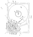
- Fig. 1 is an opened-up, and partially fragmented, plan view illustrating a miniature-format, rigid-magnetic-disk information-storage system embodying a low-mass, low-torque-resistant, combined rotary actuator structure and read/write-transducer substructure assembly constructed in accordance with the special features of the present invention.
- Fig. 2 which is on a slightly larger scale than Fig. 1, is a longitudinal section of the system shown in Fig. 1, taken as if viewed upwardly in Fig. 1.
- Fig. 3 is an enlarged view of components making up the combinational assembly of Figs. 1 and 2, exploded and isolated from other structure to illustrate details of configuration and construction.
- Fig. 4 is a still larger-scale view, taken generally along the line 4-4 in Fig. 3, to illustrate certain features of a read/write-transducer substructure which forms part of the assembly of Figs. 1, 2 and 3.
- Figs. 1 and 2 indicated generally at 10 is an information storage system in the form of a miniature, small-form-factor, rigid-disk drive system for storing digital information.
- Embodied in system 10 is a two-part housing 12 including a base 12 a and sealingly joined thereto in any suitable fashion, a cover 12 b .
- the components that make up housing 12, which are also referred to herein as the main frame in the system, enclose all of the other components which, together with the housing, make up the entirety of system 10.
- the inside of the sealed housing is maintained essentially at nominal atmospheric pressure.
- System 10 has a dimensionality with a footprint having a length of approximately 73-millimeters (the left-to-right dimension in Figs. 1 and 2), and a width of approximately 54-millimeters (the vertical dimension in Fig. 1).
- the dimensionality of system 10 also includes a height of approximately 13-millimeters (the vertical dimension seen in Fig. 2). Given these measurements, the dimensionality of system 10 occupies a volume of only about 50-centimeters 3 .
- This system dimensionality corresponds specifically to a 48-millimeter media form factor (as is defined by the diameter of a single rigid disk, still to be mentioned, which is contained for operation within housing 12 in the system illustrated in Figs. 1 and 2).
- the present invention while having special utility in the setting of a small-form-factor disk-drive system, can be used just as well, and to great advantage in larger-form-factor systems, and in systems which employ read/write heads, and suspensions therefor, which are different from the specific counterparts illustrated herein in system 10.
- the apparatus and method of the invention can be employed in systems employing low-mass flying heads.
- a low-powered, brushless, DC spindle motor 14 (Fig. 2) which includes a coil-carry stator 14 a mounted suitably on the outside of a hollow, cylindrical supporting boss 12 c (Fig. 2) formed in housing base 12 a .
- Motor 14 also includes a permanent-magnet rotor 14 b (also Fig. 2) which is suitably joined, with the disposition shown, to a lightweight rotary spindle 16.
- Spindle 16 is mounted through a journal bearing 20 (Fig. 2) which is seated within the hollow interior of boss 12 c for rotation about an axis shown at 18.
- motor 14 functions to maintain an accurate, constant spindle rotational speed of about 5400-rpm.
- Disk 24 Supported on the upper side of spindle 16 (for rotation as a unit therewith) through a suitable clamp 22 is a rigid magnetic recording disk, or recording medium, 24 which is prepared on its opposite axial sides with magnetic layer structure for two-sided reading and writing of digitized information. These two sides of disk 24 are shown at 24 a , 24 b , and the magnetic recording layer structure (just mentioned) on each of the disk's sides is referred to as a recording surface. Disk 24 has an outer diameter herein of only 48-millimeters, and an overall thickness of only about 0.63-millimeters. It is the outer diameter of disk 24 which gives rise to the identification of system 10 as having a dimensionality corresponding to a 48-millimeter media form factor. The disk's small diameter contributes, inter alia , to low-mass, low-power-requirement spinning operation.
- each recording surface takes the form an underlying magnetic flux-return layer with an in-plane magnetic anisotropy, and an outer, or overlying, hard magnetic recording layer with an out-of-plane magnetic anisotropy.
- the recording surfaces are each protected by a hard, smooth carbon overcoat, and by a lubricant layer, to minimize head and disk wear.
- each of structures 26, 28 includes a read/write head structure, or transducer (which will be pointed out shortly with reference to Fig. 4) carried adjacent the distal end of the structure, which end has a hardened contact pad (not specifically illustrated) that is substantially continuously in contact with the respective associated recording surface in disk 24.
- the distal ends of structures 26, 28 are shown at 26 a , 28 b , respectively.
- each of these elongate flexure structures is mounted with its cantilevered, free end at an angle of about 4-degrees with respect to the associated surface of disk 24, and with such free end contacting the associated disk surface (through the hardened contact pad mentioned above with a force also mentioned above) of about 40-milligrams.
- assembly 30 including a rotary actuator structure 32 and a read/write-transducer substructure 34 which includes previously mentioned flexure structures 26, 28.
- this assembly is referred to as a low-mass, low-torque-resistant assembly.
- Assembly 30 is journaled (as will be explained) on the inside of a hollow, cylindrical boss 12 d (see Fig. 2) formed in housing base 12 a through a journal bearing assembly 36 for reciprocal rotation about a journal axis shown at 38.
- Actuator structure 32 functions, and is thus referred to herein, as a carrier for the transducers which form part of structures 26, 28.
- Actuator structure 32 includes a frame component 40 which has a main body portion 40 a including a hub 40 b which is hollow, as is indicated in Fig. 3, at 40 c .
- a frame component 40 Joined to the main body and hub portion of this frame component, and diverging generally radially with respect to the central axis of the hollow central portion of hub 40 b , are two elongate legs 40 d , 40 e .
- Frame component 40 is fastened to the outside of an elongate, cylindrical, hollow pivot pin 44 which is suitably mounted within the inside of journal bearing assembly 36, generally as is shown in Figs. 2 and 3.
- the actuator frame component is thus mounted on housing base 12 a for turning on previously mentioned journal axis 38.
- actuator structure 32 Also included in actuator structure 32 is an actuator motor, or motor means, 46 which includes, as its rotor (or first interactive reaction element), a winding 48, and as its stator, which is effectively mounted on housing 12, and which is also referred to as a second interactive reaction element, a structure 50 including a pair of oppositely magnetically oriented permanent magnets 50 a , 50 b , and lower and upper, magnetically permeable pole plates 50 c , 50 d , respectively, which are appropriately mounted within housing 12. Magnets 50 a , 50 b are oriented with their poles vertically displaced, as one views them generally in Figs. 2 and 3. A space shown at 50 e in Fig.
- the turns in winding 48 are supported and suitably mounted as shown on actuator frame component 40.
- These turns include legs 48 a , 48 b , which extend along the outside of previously mentioned legs 40 d , 4 e , respectively, a stretch 48 c which extends between the distal ends of legs 40 d , 40 e , and a curvilinear run 48 d which curls about body portion 40 a as illustrated.
- the mass of winding 48 is distributed in such a fashion that portions are on opposite sides of a transverse plane 51 (see Fig. 1) which contains journal axis 38 and which is normal to the plane of Fig. 2 in the drawings.
- winding 48 shown at 48 f and 48 g in Fig. 3 are attached to suitable connector pads provided on circuit board 42 adjacent hub 40 b . According to another important feature of the present invention, these ends communicate with outside circuitry through a slender, nearly zero-torque-generating stretch of conductors, or conductor means, shown at 56 in Figs. 2 and 3 which extend generally on and substantially coincidentally along journal axis 38, through the hollow interiors of hub 40 b and pivot pin 44.
- This slender conductor structure carries, in addition to the two conductors which are necessary for the energizing of winding 48, other conductors, not specifically illustrated, which connect through a junction region, shown generally in dashed lines at 58 in Fig. 3, with signal-carrying structure, such as conductors that extend toward the coils that are associated with the transducers in structures 26, 28. Winding 48 and this signal-carrying structure are referred to herein collectively as electrical current-utilizing structure.
- an end of this "axial" space may be sealed by a suitable material, such as an epoxy material.
- Read/write transducer substructure 34 includes a mounting body 34 a which is suitably joined to frame component 40 for rotation as a unit therewith, from which body project two elongate arms 34 b , 34 c which have the general configurations shown, which arms mount and support previously mentioned head/flexure/conductor structures 26, 28, respectively.
- the long axis of substructure 34 is disposed substantially within the plane of Figs. 1 and 2, and normal to the plane of Fig. 4. Referring to Fig. 4 specifically, this axis can be thought of as extending also in a plane 60 which contains axis 38 and which forms a lateral, medial plane for substructure 34.
- Substructure 34 is symmetrically mass-balanced relative to plane 60.
- transducers (mentioned earlier) which are included within structures 26, 28 are shown at 26 b , 28 b , respectively, in Fig. 4.
- housing base 12 a Appropriately mounted on housing base 12 a is an angular position limiter pin 62 (see Fig. 1) which limits the swing of all of the rotary structure, through engagement with the inner surfaces of the free ends of frame component legs 40 d , 40 e , to an arc of about 30-degrees. This allows transducers 26 b , 28 b to sweep into operative positions over the full recordable expanses of recording surfaces 24 a , 24 b . A further discussion of this sweep capability is found in above-referred to co-pending patent application Serial No. 07/760,586.
- the rotary mechanism portion of the structure that is, all of that structure which rotates under the influence of motor 46 to adjust the positions of the transducers relative to the recording surfaces in disk 24, has an extremely low-mass and mass-balanced status, without the requirement that, in order to counterbalance the weight of the rotor coil in the motor, additional and unnecessary (otherwise nonoperative) mass be specially added to the transducer structure.
- This avoidance has been accomplished by forming the winding in the actuator motor in such a fashion (such as the circumscribing fashion described so far) that it has mass distributed on what might be thought of as the transducer side of the journal axis relative to other portions of the rotor winding.
- novel mass distribution proposed according to this invention for the windings in coil 48 is preferably achieved by forming this winding in a circumscribing fashion relative to journal axis 38.
Landscapes
- Moving Of Heads (AREA)
- Pulleys (AREA)
- Superconductive Dynamoelectric Machines (AREA)
- Auxiliary Devices For And Details Of Packaging Control (AREA)
Claims (17)
- Drehstellantriebskonstruktion zum Positionieren eines Lese-/Schreib-Wandlers relativ zu einer Aufzeichnungsoberfläche eines Aufzeichnungsmediums in einem Plattenlaufwerk-System, wobei die Stellantriebskonstruktion aufweist:dadurch gekennzeichnet,ein Stellantriebsrahmen-Bauteil, das so ausgebildet ist, daß es den Wandler wirksam tragen kann, und das wirksam an dem Hauptrahmen des Systems zur Drehung um eine definierte stellantrieb-Lagerzapfenachse gelagert ist, undeine Stellantrieb-Motoreinrichtung, die antreibend mit dem Bauteil verbunden ist und dieses in eine Drehbewegung um besagte Achse versetzen kann, wobei die Motoreinrichtung erste und zweite relativ zueinander drehbare, aufeinander einwirkende Gegenwirkelemente aufweist, wobei das erste Element mit dem Bauteil verbunden ist, um sich mit diesem als Einheit zu bewegen,
daß das erste Element eine Konfiguration hat, die in einer die Lagerzapfenachse umschließenden Weise verteilt ist, wodurch die Masse des ersten Elements ebenfalls derartig verteilt ist. - Stellantriebskonstruktion nach Anspruch 1, wobei das erste Element der Rotorabschnitt der Motoreinrichtung ist.
- Stellantriebskonstruktion nach Anspruch 1 oder 2, wobei das erste Element die Wicklung in der Motoreinrichtung aufweist.
- Stellantriebskonstruktion nach Anspruch 3, wobei die Wicklung in einer zu der Lagerzapfenachse im wesentlichen senkrechten Ebene liegt und eine mit leicht abgerundeten Kanten versehene keilförmige Konfiguration ohne Spitze aufweist.
- Stellantriebskonstruktion nach Anspruch 4, wobei das zweite Element der Motoreinrichtung ein auf dem Hauptrahmen befestigter Stator ist, der einen Fluß-Spalt aufweist, und wobei die keilförmige Konfiguration ein Paar sich im wesentlichen radial erstreckender Schenkel aufweist, die innerhalb des Spalts angeordnet sind.
- Stellantriebskonstruktion nach einem der Ansprüche 3, 4 oder 5, bei der Zuleitungen mit gegenüberliegenden elektrischen Enden der Wicklung verbunden sind, wobei sich die Zuleitungen im wesentlichen auf und entlang der Lagerzapfenachse von den Enden weg erstrecken.
- Stellantriebskonstruktion nach Anspruch 1, wobei das Rahmenbauteil eine Nabe und ein Paar benachbarter, auseinanderlaufender, und im wesentlichen radial verlaufender Schenkel aufweist, die auf einer Seite der Lagerzapfenachse mit der Nabe verbunden sind.
- Stellantriebskonstruktion nach Anspruch 7, wobei das erste Element die Wicklung der Motoreinrichtung aufweist, wobei die Wicklung die Form mehrerer Windungen annimmt, die auf einer Bahn verlaufen, die um die Nabe verteilt ist und die sich entlang der Schenkel und zwischen deren freien Enden erstreckt.
- Stellantriebskonstruktion nach Anspruch 8, wobei die Nabe entlang der Lagerzapfenachse hohl ausgebildet ist, wobei die Wicklung ein Paar von elektrisch gegenüberliegenden Enden aufweist, die benachbart zu der Nabe in der Nähe der Achse angeordnet sind, wobei an deren Enden zwei langgestreckte elektrische Leitungen vorgesehen sind, welche mit den Enden verbunden sind und sich durch den Hohlraum in der Nabe im wesentlichen auf und entlang der Lagerzapfenachse erstrecken.
- Drehstellantriebskonstruktion nach Anspruch 1, wobei der Wandler bezüglich der Achse auf einer ausgewählten Seite des Bauteils angeordnet ist, wobei das erste Motorelement eine Wicklung aufweist, die die Lagerzapfenachse umgibt und die einen Schwerpunkt hat, der bezüglich der Lagerzapfenachse gegenüber der ausgewählten Seite des Bauteils entgegengesetzt angeordnet ist und wobei die Wicklung einen Abschnitt aufweist, der zu einer Verschiebung ihrer Gesamtmasse in Richtung auf die ausgewählte Seite des Bauteils in Bezug auf die Lagerzapfenachse beiträgt.
- Drehwiderstandsarme Anordnung geringer Masse mit einer Kombination einer Drehstellantriebskonstruktion nach Anspruch 1 und einer Lese-/Schreib-Wandler-Unterkonstruktion, wobei die Wandler-Unterkonstruktion langgestreckt ausgebildet und mit einem Ende mit dem Bauteil verbunden ist, um sich mit ihm als Einheit zu bewegen, und sich von dem Ende entlang seiner Längsachse bis zu einem freien Ende erstreckt, das einen Lese-/Schreib-Wandler aufweist, wobei die Längsachse im wesentlichen senkrecht zu einer die Lagerzapfenachse enthaltenden definierten Ebene angeordnet ist, undwobei das erste Element der Stellantrieb-Motoreinrichtung und dementsprechend auch die Wandler-Unterkonstruktion eine Konfiguration hat, bei der auf beiden gegenüberliegenden Seiten der Ebene Masse angeordnet ist,wobei die jeweiligen kombinierten Massen aller auf den gegenüberliegenden Seiten der Ebene angeordneten Bestandteile der Anordnung im wesentlichen gleich groß sind.
- Anordnung nach Anspruch 11, wobei das erste Element eine Wicklung und darüber hinaus elektrische Leitungsmittel aufweist, die im wesentlichen auf und entlang der Lagerzapfenachse verlaufen und die einzige elektrische Verbindung mit einer externen Struktur darstellen, und die zumindest ein Paar von Leitungen aufweisen, die mit den gegenüberliegenden elektrischen Enden der Wicklung verbunden sind.
- Drehstellantriebskonstruktion zum Positionieren eines Lese-/Schreib-Wandlers relativ zu einer Aufzeichnungsoberfläche eines Aufzeichnungsmediums in einem Plattenlaufwerkssystem, wobei die Stellantriebskonstruktion aufweist:dadurch gekennzeichnet, daßeinen Rotormechanismus, der zur Drehung um eine definierte Lagerzapfenachse wirksam an dem Hauptrahmen des Systems gelagert ist, undeiner Leitungswicklung,
die Wicklung die Lagerzapfenachse umgibt und mit dem Mechanismus verbunden ist, wobei durch die Wicklung Strom fließt, um eine Drehung des Mechanismus zu bewirken und wobei die Wicklung in einer Weise angeordnet ist, daß sie einen Bogen von mindestens 180° um die Achse beschreibt. - Stellantriebskonstruktion nach Anspruch 13, wobei die Wicklung einen 360°-Bogen beschreibt.
- Stellantriebskonstruktion nach Anspruch 13 oder 14, wobei an die gegenüberliegenden elektrischen Enden der Wicklung Leitungen angeschlossen sind, die sich im wesentlichen auf und entlang der Lagerzapfenachse in Richtung von den Enden weg erstrecken.
- Verfahren zum Anordnen von Bestandteilen in einer aus einer Drehstellantriebskonstruktion und einer Lese-/Schreib-Wandler-Unterkonstruktion kombinierten Baugruppe zum Erzielen einer reaktionsschnellen und einen geringen Widerstand bewirkenden Arbeitsweise, wobei die Baugruppe dem Positionieren eines Wandlers in der Baugruppe relativ zu einer Aufzeichnungsoberläche eines Aufzeichnungsmediums in einem Plattenlaufwerksystem dient, und wobei das Verfahren umfaßt:Anordnen einer Drehantriebsmotorwicklung auf einem zum Tragen einer derartigen Wandler-Unterkonstruktion geeigneten Stellantriebs-Rahmen-Bauteil derart, daß dem Bauteil zur Verfügung gestellter Strom in einem eine Lagerzapfenachse umgebenden Pfad geleitet wird und daß die Gesamtmasse der Wicklung um diese Achse verteilt wird,konstruktives Kombinieren der Wandler-Unterkonstruktion mit dem Rahmenbauteil und der Wicklung derart, daß die Kombination von Bauteil, Wicklung und Unterkonstruktion eine im Bezug auf die Achse dynamisch ausbalancierte Anordnung bildet, undVerlegen von die Wicklung versorgenden elektrischen Leitern in einer nicht-flexiblen drehmoment-unabhängigen Weise zu den entgegengesetzten elektrischen Enden der Wicklung im wesentlichen auf und entlang der Lagerzapfenachse.
- Verfahren nach Anspruch 16, wobei auf dem Stellantrieb-Rahmenbauteil, das die sich auf einer ihrer Seiten und von ihr weg erstreckende Wandler-Unterkonstruktion wirksam tragen kann, die drehbare Antriebsmotor-Wicklung so angeordnet wird, daß Strom in einem Pfad geleitet wird, der sowohl auf der Unterkonstruktionsseite des Bauteils als auch auf dessen bezüglich der für das Bauteil vorgesehenen Lagerzapfenachse gegenüberliegenden Seite verteilt ist.
Applications Claiming Priority (2)
| Application Number | Priority Date | Filing Date | Title |
|---|---|---|---|
| US843895 | 1992-02-27 | ||
| US07/843,895 US5396388A (en) | 1992-02-27 | 1992-02-27 | Compact, high-speed, rotary actuator and transducer assembly with reduced moment of inertia and mass-balanced structural overlap with drive motor and organizing method for the same |
Publications (3)
| Publication Number | Publication Date |
|---|---|
| EP0558355A2 EP0558355A2 (de) | 1993-09-01 |
| EP0558355A3 EP0558355A3 (de) | 1993-09-22 |
| EP0558355B1 true EP0558355B1 (de) | 1998-08-19 |
Family
ID=25291271
Family Applications (1)
| Application Number | Title | Priority Date | Filing Date |
|---|---|---|---|
| EP93301532A Expired - Lifetime EP0558355B1 (de) | 1992-02-27 | 1993-03-01 | Kompakter rotierender Hochgeschwindigkeitsantrieb |
Country Status (6)
| Country | Link |
|---|---|
| US (2) | US5396388A (de) |
| EP (1) | EP0558355B1 (de) |
| JP (1) | JPH06168549A (de) |
| AT (1) | ATE170018T1 (de) |
| CA (1) | CA2090543C (de) |
| DE (1) | DE69320387D1 (de) |
Families Citing this family (20)
| Publication number | Priority date | Publication date | Assignee | Title |
|---|---|---|---|---|
| US5557152A (en) * | 1990-06-21 | 1996-09-17 | Seagate Technology, Inc. | 2-Pole single or dual coil moving magnet motor with moving back iron |
| US5717549A (en) * | 1991-05-29 | 1998-02-10 | Hutchinson Technology Incorporated | Low profile head disk assembly in which the actuator member and the disks of the assembly are nonoverlapping |
| US5659215A (en) * | 1994-05-19 | 1997-08-19 | Seagate Technology, Inc. | Small form factor actuator for improved functionality and linearity |
| WO1997017698A1 (en) * | 1995-11-09 | 1997-05-15 | Iomega Corporation | Low inertia flux motor rotary actuator |
| US5831791A (en) * | 1996-03-27 | 1998-11-03 | Headway Technologies, Inc. | Negative Pressure air bearing slider having transition region between positive and negative pressure regions |
| US6201322B1 (en) * | 1997-03-19 | 2001-03-13 | Seagate Technology Llc | Brushless spindle DC motor used as an actuator to create radial force |
| JP4034358B2 (ja) * | 1997-03-19 | 2008-01-16 | シーゲイト テクノロジィ リミテッド ライアビリティ カンパニー | 半径方向の力を発生するdcモータアクチュエータ |
| US5966271A (en) | 1997-04-30 | 1999-10-12 | Seagate Technology, Inc. | Apparatus for assembling a magnet and backiron for a voice coil motor |
| US5883761A (en) * | 1997-07-21 | 1999-03-16 | Quantum Corporation | Magnetic read/write head actuator assembly having asymmetric stator magnets |
| JPH11259967A (ja) * | 1998-03-09 | 1999-09-24 | Alps Electric Co Ltd | ディスクの回転駆動装置およびその製造方法 |
| US6293029B1 (en) * | 1998-08-27 | 2001-09-25 | Seagate Technology Llc | Measurement instrument for components of a voice coil motor |
| US6654208B2 (en) | 2000-08-23 | 2003-11-25 | Seagate Technology Llc | Reduced inertia actuator pivot assembly |
| US9491275B2 (en) * | 2005-09-15 | 2016-11-08 | AT&T Intellectual Property I, L.P., by transfer of ownership from AT&T | Systems, methods and computer program products for aggregating contact information |
| US7576954B2 (en) * | 2006-02-16 | 2009-08-18 | Sae Magnetics H.K. Ltd. | Symmetric voice coil motor design, assembly methods of constructing same, and hard disk micro drive storage systems including same |
| US7839598B2 (en) * | 2008-02-08 | 2010-11-23 | International Business Machines Corporation | Balanced linkage actuation of tape head |
| US8228635B2 (en) | 2008-02-08 | 2012-07-24 | International Business Machines Corporation | Friction engaged tilting roller bearing tape guidance |
| US7649710B2 (en) * | 2008-02-08 | 2010-01-19 | International Business Machines Corporation | Moving magnet actuation of tape head |
| US8270114B2 (en) | 2008-02-08 | 2012-09-18 | International Business Machines Corporation | Magnetically biased tilting roller bearing tape guidance |
| JP2010225207A (ja) * | 2009-03-19 | 2010-10-07 | Alphana Technology Co Ltd | ディスク駆動装置 |
| US9093094B2 (en) * | 2013-12-03 | 2015-07-28 | HGST Netherlands B.V. | Hard disk drive actuator assembly with interleaved voice coil motor |
Family Cites Families (22)
| Publication number | Priority date | Publication date | Assignee | Title |
|---|---|---|---|---|
| US4490635A (en) * | 1980-09-24 | 1984-12-25 | Quantum Corporation | Pure torque, limited displacement transducer |
| US4476404A (en) * | 1983-09-23 | 1984-10-09 | Tandon Corporation | Flexible conductor for supplying current to a pivotally movable electrical element |
| US4707754A (en) * | 1985-08-07 | 1987-11-17 | Apple Computer, Inc. | Voice coil balanced actuator |
| JPS62231476A (ja) * | 1986-04-01 | 1987-10-12 | Hitachi Ltd | 磁気デイスク装置のヘツド位置決め機構 |
| DE3789391T2 (de) * | 1986-06-04 | 1994-06-23 | Fujitsu Ltd | Magnet-Scheibengerät. |
| JPH01130365A (ja) * | 1987-11-17 | 1989-05-23 | Mitsubishi Electric Corp | 磁気デイスク装置の磁気ヘツド位置決め機構 |
| JPH01231649A (ja) * | 1988-03-09 | 1989-09-14 | Hitachi Ltd | 回転駆動装置 |
| US4923406A (en) * | 1988-11-17 | 1990-05-08 | Magnetic Peripherals Inc. | Spindle motor flex cable |
| JP2843039B2 (ja) * | 1988-12-09 | 1999-01-06 | 株式会社日立製作所 | 磁気ディスク装置の組立方法 |
| US5041934A (en) * | 1989-04-24 | 1991-08-20 | Conner Peripherals, Inc. | Actuator for disk drive |
| US5016131A (en) * | 1989-04-26 | 1991-05-14 | Digital Equipment Corporation | Integral balanced-moment head positioner |
| US5025335B1 (en) * | 1989-07-31 | 1995-12-26 | Conner Peripherals Inc | Architecture for 2 1/2 inch diameter single disk drive |
| US5018035A (en) * | 1989-10-30 | 1991-05-21 | Toshiba America Information Systems, Inc. | Disc storage apparatus having an arcuate pivot assembly |
| US5025336A (en) * | 1989-11-06 | 1991-06-18 | Prairietek Corporation | Disk drive apparatus |
| JPH0371457U (de) * | 1989-11-13 | 1991-07-19 | ||
| US5111351A (en) * | 1989-11-27 | 1992-05-05 | Censtor Corp. | Integrated magnetic read/write head/flexure/conductor structure |
| US5073242A (en) * | 1989-11-27 | 1991-12-17 | Censtor Corp. | Method of making integrated magnetic read/write head/flexure/conductor structure |
| US5041932A (en) * | 1989-11-27 | 1991-08-20 | Censtor Corp. | Integrated magnetic read/write head/flexure/conductor structure |
| JPH0453072A (ja) * | 1990-06-19 | 1992-02-20 | Hitachi Ltd | ロータリー型ヘッド位置決め装置 |
| US5172282A (en) * | 1990-06-29 | 1992-12-15 | Seagate Technology, Inc. | Single motor data storage device utilizing centrifugal force and counteracting spring |
| US5218496A (en) * | 1990-12-06 | 1993-06-08 | Kalok Corporation | Magnetic disk drive with reduced disk-to-disk spacing and improved actuator design |
| US5064377A (en) * | 1990-12-28 | 1991-11-12 | Seagate Technology, Inc. | Compression contact electrical connector assembly for a disc drive |
-
1992
- 1992-02-27 US US07/843,895 patent/US5396388A/en not_active Expired - Lifetime
-
1993
- 1993-02-26 CA CA002090543A patent/CA2090543C/en not_active Expired - Fee Related
- 1993-03-01 EP EP93301532A patent/EP0558355B1/de not_active Expired - Lifetime
- 1993-03-01 AT AT93301532T patent/ATE170018T1/de not_active IP Right Cessation
- 1993-03-01 DE DE69320387T patent/DE69320387D1/de not_active Expired - Lifetime
- 1993-03-01 JP JP5066135A patent/JPH06168549A/ja active Pending
-
1995
- 1995-01-20 US US08/389,964 patent/US5625515A/en not_active Expired - Fee Related
Also Published As
| Publication number | Publication date |
|---|---|
| CA2090543C (en) | 1999-03-16 |
| ATE170018T1 (de) | 1998-09-15 |
| DE69320387D1 (de) | 1998-09-24 |
| US5396388A (en) | 1995-03-07 |
| CA2090543A1 (en) | 1993-08-28 |
| US5625515A (en) | 1997-04-29 |
| JPH06168549A (ja) | 1994-06-14 |
| EP0558355A2 (de) | 1993-09-01 |
| EP0558355A3 (de) | 1993-09-22 |
Similar Documents
| Publication | Publication Date | Title |
|---|---|---|
| US5396388A (en) | Compact, high-speed, rotary actuator and transducer assembly with reduced moment of inertia and mass-balanced structural overlap with drive motor and organizing method for the same | |
| CA2081511C (en) | Size-independent, rigid-disk, magnetic, digital-information storage system with localized read/write enhancements | |
| US5956213A (en) | Latch mechanism for disk drive using magnetic field of actuator magnets | |
| EP0921525B1 (de) | Plattenlaufwerk | |
| US5872688A (en) | Miniature hard disk drive having linear loud-beam suspension and thin voice coil motor | |
| US5986852A (en) | High capacity, high performance low profile disk drive | |
| US5914836A (en) | Cantilevered support for the magnetic circuit of a disc drive voice coil motor | |
| US6765759B2 (en) | Resonance four piece suspension | |
| PL179626B1 (pl) | Zespól pamieci dyskowej PL PL PL | |
| US6417992B2 (en) | Head assembly and disk drive | |
| EP0556287A4 (en) | High performance disk drive architecture | |
| KR20000028686A (ko) | 이중 코일 회전식 엑츄에이터 | |
| EP0282995B1 (de) | Elektromagnetische Abschirmstruktur zum Abschirmen eines magnetischen Servokopfes eines Magnetplattenspeichergerätes | |
| JP2001057039A (ja) | ヘッドサスペンション、ヘッド・ジンバル組立体およびアクチュエータ | |
| WO2001026099A1 (en) | Low impedance head/preamplifier chip position in a disk drive | |
| US6621651B1 (en) | Passive actuator for assisting commutational ramp loading | |
| US7038886B1 (en) | Positioner for precisely moving an E-block of a disk drive | |
| JP7631470B2 (ja) | ハードディスクドライブのマルチディスクパック積層構造 | |
| KR20000022669A (ko) | 헤드 어셈블리 및 디스크 드라이브 | |
| WO2000074049A1 (en) | Method and system for providing a disk drive in a compact flash form factor | |
| US20100328821A1 (en) | Hard disk drive | |
| US7564651B2 (en) | Integrated-lead suspension vibration-canceling member | |
| JP3704042B2 (ja) | 可撓支持緩衝装置 | |
| JP2789770B2 (ja) | トランスジューサの位置決め装置 | |
| JPH0696532A (ja) | 磁気ディスク装置 |
Legal Events
| Date | Code | Title | Description |
|---|---|---|---|
| PUAI | Public reference made under article 153(3) epc to a published international application that has entered the european phase |
Free format text: ORIGINAL CODE: 0009012 |
|
| PUAL | Search report despatched |
Free format text: ORIGINAL CODE: 0009013 |
|
| AK | Designated contracting states |
Kind code of ref document: A2 Designated state(s): AT BE CH DE DK ES FR GB GR IE IT LI LU MC NL PT SE |
|
| AK | Designated contracting states |
Kind code of ref document: A3 Designated state(s): AT BE CH DE DK ES FR GB GR IE IT LI LU MC NL PT SE |
|
| 17P | Request for examination filed |
Effective date: 19940303 |
|
| 17Q | First examination report despatched |
Effective date: 19960911 |
|
| GRAG | Despatch of communication of intention to grant |
Free format text: ORIGINAL CODE: EPIDOS AGRA |
|
| GRAG | Despatch of communication of intention to grant |
Free format text: ORIGINAL CODE: EPIDOS AGRA |
|
| GRAH | Despatch of communication of intention to grant a patent |
Free format text: ORIGINAL CODE: EPIDOS IGRA |
|
| GRAH | Despatch of communication of intention to grant a patent |
Free format text: ORIGINAL CODE: EPIDOS IGRA |
|
| GRAA | (expected) grant |
Free format text: ORIGINAL CODE: 0009210 |
|
| AK | Designated contracting states |
Kind code of ref document: B1 Designated state(s): AT BE CH DE DK ES FR GB GR IE IT LI LU MC NL PT SE |
|
| PG25 | Lapsed in a contracting state [announced via postgrant information from national office to epo] |
Ref country code: NL Free format text: LAPSE BECAUSE OF FAILURE TO SUBMIT A TRANSLATION OF THE DESCRIPTION OR TO PAY THE FEE WITHIN THE PRESCRIBED TIME-LIMIT Effective date: 19980819 Ref country code: LI Free format text: LAPSE BECAUSE OF FAILURE TO SUBMIT A TRANSLATION OF THE DESCRIPTION OR TO PAY THE FEE WITHIN THE PRESCRIBED TIME-LIMIT Effective date: 19980819 Ref country code: IT Free format text: LAPSE BECAUSE OF FAILURE TO SUBMIT A TRANSLATION OF THE DESCRIPTION OR TO PAY THE FEE WITHIN THE PRE;WARNING: LAPSES OF ITALIAN PATENTS WITH EFFECTIVE DATE BEFORE 2007 MAY HAVE OCCURRED AT ANY TIME BEFORE 2007. THE CORRECT EFFECTIVE DATE MAY BE DIFFERENT FROM THE ONE RECORDED.SCRIBED TIME-LIMIT Effective date: 19980819 Ref country code: GR Free format text: LAPSE BECAUSE OF NON-PAYMENT OF DUE FEES Effective date: 19980819 Ref country code: FR Free format text: LAPSE BECAUSE OF FAILURE TO SUBMIT A TRANSLATION OF THE DESCRIPTION OR TO PAY THE FEE WITHIN THE PRESCRIBED TIME-LIMIT Effective date: 19980819 Ref country code: ES Free format text: THE PATENT HAS BEEN ANNULLED BY A DECISION OF A NATIONAL AUTHORITY Effective date: 19980819 Ref country code: CH Free format text: LAPSE BECAUSE OF FAILURE TO SUBMIT A TRANSLATION OF THE DESCRIPTION OR TO PAY THE FEE WITHIN THE PRESCRIBED TIME-LIMIT Effective date: 19980819 Ref country code: BE Free format text: LAPSE BECAUSE OF FAILURE TO SUBMIT A TRANSLATION OF THE DESCRIPTION OR TO PAY THE FEE WITHIN THE PRESCRIBED TIME-LIMIT Effective date: 19980819 Ref country code: AT Free format text: LAPSE BECAUSE OF FAILURE TO SUBMIT A TRANSLATION OF THE DESCRIPTION OR TO PAY THE FEE WITHIN THE PRESCRIBED TIME-LIMIT Effective date: 19980819 |
|
| REF | Corresponds to: |
Ref document number: 170018 Country of ref document: AT Date of ref document: 19980915 Kind code of ref document: T |
|
| REG | Reference to a national code |
Ref country code: CH Ref legal event code: EP |
|
| REF | Corresponds to: |
Ref document number: 69320387 Country of ref document: DE Date of ref document: 19980924 |
|
| REG | Reference to a national code |
Ref country code: IE Ref legal event code: FG4D |
|
| PG25 | Lapsed in a contracting state [announced via postgrant information from national office to epo] |
Ref country code: SE Free format text: LAPSE BECAUSE OF FAILURE TO SUBMIT A TRANSLATION OF THE DESCRIPTION OR TO PAY THE FEE WITHIN THE PRESCRIBED TIME-LIMIT Effective date: 19981119 Ref country code: PT Free format text: LAPSE BECAUSE OF FAILURE TO SUBMIT A TRANSLATION OF THE DESCRIPTION OR TO PAY THE FEE WITHIN THE PRESCRIBED TIME-LIMIT Effective date: 19981119 Ref country code: DK Free format text: LAPSE BECAUSE OF FAILURE TO SUBMIT A TRANSLATION OF THE DESCRIPTION OR TO PAY THE FEE WITHIN THE PRESCRIBED TIME-LIMIT Effective date: 19981119 |
|
| PG25 | Lapsed in a contracting state [announced via postgrant information from national office to epo] |
Ref country code: DE Free format text: LAPSE BECAUSE OF FAILURE TO SUBMIT A TRANSLATION OF THE DESCRIPTION OR TO PAY THE FEE WITHIN THE PRESCRIBED TIME-LIMIT Effective date: 19981120 |
|
| EN | Fr: translation not filed | ||
| NLV1 | Nl: lapsed or annulled due to failure to fulfill the requirements of art. 29p and 29m of the patents act | ||
| REG | Reference to a national code |
Ref country code: CH Ref legal event code: PL |
|
| PG25 | Lapsed in a contracting state [announced via postgrant information from national office to epo] |
Ref country code: LU Free format text: LAPSE BECAUSE OF NON-PAYMENT OF DUE FEES Effective date: 19990301 |
|
| PGFP | Annual fee paid to national office [announced via postgrant information from national office to epo] |
Ref country code: IE Payment date: 19990303 Year of fee payment: 7 Ref country code: GB Payment date: 19990303 Year of fee payment: 7 |
|
| PLBE | No opposition filed within time limit |
Free format text: ORIGINAL CODE: 0009261 |
|
| STAA | Information on the status of an ep patent application or granted ep patent |
Free format text: STATUS: NO OPPOSITION FILED WITHIN TIME LIMIT |
|
| 26N | No opposition filed | ||
| PG25 | Lapsed in a contracting state [announced via postgrant information from national office to epo] |
Ref country code: MC Free format text: LAPSE BECAUSE OF NON-PAYMENT OF DUE FEES Effective date: 19990930 |
|
| PG25 | Lapsed in a contracting state [announced via postgrant information from national office to epo] |
Ref country code: IE Free format text: LAPSE BECAUSE OF NON-PAYMENT OF DUE FEES Effective date: 20000301 Ref country code: GB Free format text: LAPSE BECAUSE OF NON-PAYMENT OF DUE FEES Effective date: 20000301 |
|
| GBPC | Gb: european patent ceased through non-payment of renewal fee |
Effective date: 20000301 |
|
| REG | Reference to a national code |
Ref country code: IE Ref legal event code: MM4A |