EP0558593B1 - Hydrozyklonanlage - Google Patents
Hydrozyklonanlage Download PDFInfo
- Publication number
- EP0558593B1 EP0558593B1 EP91920901A EP91920901A EP0558593B1 EP 0558593 B1 EP0558593 B1 EP 0558593B1 EP 91920901 A EP91920901 A EP 91920901A EP 91920901 A EP91920901 A EP 91920901A EP 0558593 B1 EP0558593 B1 EP 0558593B1
- Authority
- EP
- European Patent Office
- Prior art keywords
- hydrocyclones
- hydrocyclone
- space
- heavy fraction
- cylindrical
- Prior art date
- Legal status (The legal status is an assumption and is not a legal conclusion. Google has not performed a legal analysis and makes no representation as to the accuracy of the status listed.)
- Expired - Lifetime
Links
Images
Classifications
-
- B—PERFORMING OPERATIONS; TRANSPORTING
- B04—CENTRIFUGAL APPARATUS OR MACHINES FOR CARRYING-OUT PHYSICAL OR CHEMICAL PROCESSES
- B04C—APPARATUS USING FREE VORTEX FLOW, e.g. CYCLONES
- B04C5/00—Apparatus in which the axial direction of the vortex is reversed
- B04C5/24—Multiple arrangement thereof
- B04C5/28—Multiple arrangement thereof for parallel flow
-
- D—TEXTILES; PAPER
- D21—PAPER-MAKING; PRODUCTION OF CELLULOSE
- D21D—TREATMENT OF THE MATERIALS BEFORE PASSING TO THE PAPER-MAKING MACHINE
- D21D5/00—Purification of the pulp suspension by mechanical means; Apparatus therefor
- D21D5/18—Purification of the pulp suspension by mechanical means; Apparatus therefor with the aid of centrifugal force
- D21D5/24—Purification of the pulp suspension by mechanical means; Apparatus therefor with the aid of centrifugal force in cyclones
Definitions
- the present invention relates to a hydrocyclone plant, comprising a great number of hydrocyclones arranged in groups, each group of hydrocyclones is made in one single piece and each hydrocyclone having an elongated separation chamber with two opposite ends, at least one inlet for a liquid mixture to be separated, a light fraction outlet at one end of the separation chamber for a separated light fraction and a heavy fraction outlet at the other end of the separation chamber for a created heavy fraction.
- An inner wall, intermediate wall and an outer wall are provided, said walls defining a cylindrical heavy fraction space, which communicates with the heavy fraction outlets, an annular inlet space, which extends concentrically around the heavy fraction space and communicates with the inlets of the hydrocyclones, and an annular light fraction space, which extends concentrically around the inlet space and communicates with the light fraction outlets.
- Each hydrocyclone extends substantially radially in said annular inlet space.
- a hydrocyclone plant of this kind is known from US 4 190 523, in which each hydrocyclone group forms a disc having a number of radially oriented hydrocyclones, said disc-shaped hydrocyclone groups being stacked.
- This known plant is not practical to use for applications which require relatively long hydrocyclones, since the discs would be too large and heavy. For instance, when cleaning fibre pulp suspensions by means of the known plant, the required long hydrocyclones would result in discs having a diameter exceeding at least two metres. Such large discs would be difficult to disassemble from the stack of discs for servicing and repairing individual hydrocyclones.
- US 2 956 679 which is acknowledged as prior art in US 4 190 523, relates to a radial multihydrocylone plant, in which individual hydrocyclones are arranged within a casing. US 2 959 679 also provides for the formation of a disc containing a number of radially oriented hydrocyclones.
- the object of the present invention is to provide a hydrocyclone plant of this kind, which is compact, is suited for relatively long hydrocyclones, and enables easy servicing of the individual hydrocyclones.
- hydrocyclone plant of the kind initially stated which is characterised in that each group consists of three hydrocyclones, and the groups of hydrocyclones are distributed around the cylindrical heavy fraction space in the circumferential direction of the latter and are spaced from one another in the inlet space to allow said liquid mixture to flow between adjacent groups of hydrocyclones.
- each group of hydrocyclones is releasably attached to said walls, and each group is accessible and removable through an opening in the outer wall which is normally closed by a cover.
- Each hydrocyclone is suitably designed with a cylindrical chamber, which communicates directly with the inlet and the light fraction outlet, and a tapered chamber, which communicates directly with the heavy fraction outlet, the cylindrical chambers in each group of hydrocyclones extending in parallel with one another, whereas the centre axes of the tapered chambers of the group converge in direction towards the apexes of the tapered chambers. In this manner the hydrocyclones of each group of hydrocyclones can be packed closer to one another.
- each hydrocyclone the centre axis of the cylindrical chamber and the centre axis of the tapered chamber suitably form an angle to one another, such that in an axial section through the hydrocyclone the wall of the chambers coincide with a straight line.
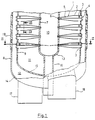
- figure 1 schematically shows a view of a part section of a hydrocyclone plant according to the invention
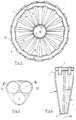
- figure 2 shows a section along the line II-II in figure 1
- figure 3 shows a section along the line III-III in figure 1
- figure 4 shows a section along the line IV-IV in figure 3.
- the hydrocyclone plant shown in the figures comprises a number of elongated hydrocyclones 1 arranged in groups of three hydrocyclones.
- Each hydrocyclone 1 has a separation chamber consisting of a cylindrical chamber 2 and a conical chamber 5.
- the cylindrical chamber 2 has a peripheral inlet 3 for a liquid mixture to be separated and a central light fraction outlet 4 for a created light fraction.
- the conical chamber 5 has a heavy fraction outlet 6 at the apex of the conical chamber 5 for a created heavy fraction.
- Three cylindrical vertical walls, an inner wall 7, an outer wall 8 and an intermediate wall 9 are arranged concentrically with one another and define a cylindrical heavy fraction space 10 in the interior of the inner wall 7, an annular inlet space 11 between the inner wall 7 and the intermediate wall 9, and an annular light fraction space 12 between the intermediate wall 9 and the outer wall 8.
- the walls 7-9 are provided with bottom walls 13-15, which have an outlet member 16 for heavy fraction, and outlet member 17 for light fraction and an inlet member 18 for the liquid mixture to be separated.
- the groups of hydrocyclones 1 extend substantially radially in the annular inlet space 11 and are evenly distributed around the cylindrical heavy fraction space 10 on several levels along the cylindrical walls 7-9.
- the inlet 3, the heavy fraction outlet 6 and the light fraction outlet 4 of the hydrocyclones communicate with the inlet space 11, the heavy fraction space 10 and the light fraction space 12, respectively.
- Each group of hydrocyclones is made in one single piece (fig 3 and 4), which is releasable from the hydrocyclone plant via a hole arranged in the outer wall 8 in front of said piece. Said hole is normally closed by a lid 19.
- each group of hydrocyclones 11 the cylindrical chambers 2 extend in parallel with one another, whereas the centre axes of the conical chambers 5 converge in direction towards the apexes of the conical chambers 5.
- the centre axis of the cylindrical chamber 2 and the centre axis of the conical chamber 5 form an angle ⁇ to one another, such that in an axial section through the hydrocyclone 1 the wall of the chambers 2,5 coincide with a straight line 20 (fig 4).
- the liquid mixture to be separated is pumped to the inlet space 11 via the inlet member 18.
- the liquid mixture flows under a relatively little flow resistance between the groups of hydrocyclones to the individual hydrocyclones 1 and enters these via the inlets 3.
- the liquid mixture is separated into a light fraction and a heavy fraction, which flows through the heavy fraction outlet 6 and which is collected in the heavy fraction space 10, from which the heavy fraction is discharged from the hydrocyclone plant via the outlet member 16.
- the light fraction flows through the light fraction outlet 4 and is collected in the light fraction space 12, from which the light fraction is discharged from the hydrocyclone plant via the outlet member 17.
Landscapes
- Engineering & Computer Science (AREA)
- Mechanical Engineering (AREA)
- Organic Low-Molecular-Weight Compounds And Preparation Thereof (AREA)
- Extraction Or Liquid Replacement (AREA)
- Cyclones (AREA)
- Transition And Organic Metals Composition Catalysts For Addition Polymerization (AREA)
- Materials For Medical Uses (AREA)
- Devices And Processes Conducted In The Presence Of Fluids And Solid Particles (AREA)
- Low-Molecular Organic Synthesis Reactions Using Catalysts (AREA)
- Measuring Volume Flow (AREA)
Claims (4)
- Hydrozyklonanlage, umfassendeine Vielzahl von Hydrozyklonen (1), die in Gruppen angeordnet sind, wobei jede Gruppe von Hydrozyklonen in einem Stück gefertigt ist und jedes Hydrozykloneine verlängerte Trennkammer (2,5) mit zwei gegenüberliegenden Enden aufweist, sowiemindestens einen Einlaß (3) für ein zu trennendes Flüssigkeitsgemisch,einen Auslaß (4) für die leichte Fraktion für eine abgetrennte leichte Fraktion an einem Ende der Trennkammer,einen Auslaß (6) für die schwere Fraktion für eine abgetrennte schwere Fraktion am anderen Ende der Trennkammer,eine Innenwand (7), eine Zwischenwand (9) und eine Außenwand (8), wobei die Wände einen zylindrischen Raum (10) für die schwere Fraktion bilden, der mit dem Auslaß (6) für die schwere Fraktion in Verbindung steht,einen ringförmigen Einlaßraum (11), der sich konzentrisch um den Raum (10) für die schwere Fraktion herum erstreckt und mit den Einlässen (3) der Hydrozklonen verbunden ist, undeinen ringförmigen Raum (12) für die leichte Fraktion, der sich konzentrisch um den Einlaßraum (11) herum erstreckt und mit den Auslässen für die leichte Fraktion in Verbindung steht, wobei sich jeder Hydrozyklon im wesentlichen radial in den ringförmigen Raum hinein erstreckt,
dadurch gekennzeichnet, daßjede Gruppe aus drei Hydrozyklonen besteht unddie Gruppen von Hydrozyklonen um den zylindrischen Raum (10) für die schwere Fraktion in Richtung von dessen Umfang herum verteilt sind und im ringförmigen Einlaßraum (11) einen Abstand voneinander haben, damit das Flüssigkeitsgemisch zwischen benachbarten Gruppen von Hydrozyklonen fließen kann. - Hydrozyklonanlage nach Anspruch 1, dadurch gekennzeichnet, daß jede Gruppe von Hydrozyklonen (1) lösbar mit den Wänden (7-9) verbunden ist und jede Gruppe zugänglich und entfernbar ist durch eine Öffnung in der Außenwand (8), die normalerweise durch eine Abdeckung verschlossen ist.
- Hydrozyklonanlage nach Anspruch 1 oder 2, in der jede Trennkammer eine zylindrische Kammer (2) umfaßt, die in direkter Verbindung mit dem Einlaß (3) und dem Auslaß (4) für die leichte Fraktion steht, und eine verjüngte Kammer (5), die in direkter Verbindung mit dem Auslaß (6) für die schwere Fraktion steht, dadurch gekennzeichnet, daß sich in jeder Gruppe von Hydrozyklonen (1) die zylindrischen Kammern (2) parallel zueinander erstrecken, wobei die Mittelachsen der verjüngten Kammern (5) in Richtung der Scheitelpunkte der verjüngten Kammern (5) zusammenlaufen.
- Hydrozyklonanlage nach Anspruch 3, dadurch gekennzeichnet, daß die Mittelachse der zylindrischen Kammer (2) und die Mittelachse der verjüngten Kammer (5) in jedem Hydrozyklon (1) miteinander einen Winkel (α) bilden, so daß die Wände der Kammern bei einem axialen Schnitt durch den Hydrozyklon mit einer geraden Linie (20) zusammenfallen.
Applications Claiming Priority (3)
| Application Number | Priority Date | Filing Date | Title |
|---|---|---|---|
| SE9003746A SE503593C2 (sv) | 1990-11-26 | 1990-11-26 | Hydrocyklonanläggning |
| SE9003746 | 1990-11-26 | ||
| PCT/SE1991/000803 WO1992009371A1 (en) | 1990-11-26 | 1991-11-26 | Hydrocyclone plant |
Publications (2)
| Publication Number | Publication Date |
|---|---|
| EP0558593A1 EP0558593A1 (de) | 1993-09-08 |
| EP0558593B1 true EP0558593B1 (de) | 1997-08-20 |
Family
ID=20381001
Family Applications (1)
| Application Number | Title | Priority Date | Filing Date |
|---|---|---|---|
| EP91920901A Expired - Lifetime EP0558593B1 (de) | 1990-11-26 | 1991-11-26 | Hydrozyklonanlage |
Country Status (9)
| Country | Link |
|---|---|
| US (1) | US5337899A (de) |
| EP (1) | EP0558593B1 (de) |
| JP (1) | JPH06502799A (de) |
| AT (1) | ATE157026T1 (de) |
| CA (1) | CA2096438C (de) |
| DE (1) | DE69127373T2 (de) |
| FI (1) | FI103768B1 (de) |
| SE (1) | SE503593C2 (de) |
| WO (1) | WO1992009371A1 (de) |
Families Citing this family (9)
| Publication number | Priority date | Publication date | Assignee | Title |
|---|---|---|---|---|
| US5728262A (en) * | 1996-06-21 | 1998-03-17 | Tetra Laval Holdings & Finance, S.A. | Method and apparatus for removing neutral buoyancy contaminants from acellulosic pulp |
| US6517733B1 (en) | 2000-07-11 | 2003-02-11 | Vermeer Manufacturing Company | Continuous flow liquids/solids slurry cleaning, recycling and mixing system |
| MY134342A (en) * | 2001-12-31 | 2007-12-31 | Shell Int Research | Multistage fluid separation assembly and method |
| EP1356867B1 (de) * | 2002-04-23 | 2007-05-30 | Petreco International Limited | Hydrozyklonabscheider-Zusammenbau |
| WO2009016332A1 (en) * | 2007-07-30 | 2009-02-05 | Merpro Tortek Ltd | Cyclone apparatus |
| US9016481B2 (en) | 2009-07-17 | 2015-04-28 | Cameron International Corporation | Compacted hydrocyclone apparatus in vessels |
| US8490798B2 (en) * | 2009-07-17 | 2013-07-23 | Cameron International Corporation | Compacted hydrocyclone apparatus in vessels |
| US8932472B2 (en) | 2011-10-25 | 2015-01-13 | National Oilwell Varco, L.P. | Separator system and related methods |
| CN110064532B (zh) * | 2018-10-25 | 2024-06-28 | 中国石油大学(华东) | 一种复合式动态水力旋流器 |
Family Cites Families (9)
| Publication number | Priority date | Publication date | Assignee | Title |
|---|---|---|---|---|
| US3486618A (en) * | 1966-09-13 | 1969-12-30 | Nils Anders Lennart Wikdahl | Multiple-cyclone separator installation |
| CH509104A (fr) * | 1970-02-25 | 1971-06-30 | Doucet S A | Appareil séparateur de particules dans un liquide |
| NL7701686A (nl) * | 1977-02-17 | 1978-08-21 | Scholten Honig Research Nv | Radiale multihydrocycloon. |
| SE412169B (sv) * | 1977-03-09 | 1980-02-25 | Alfa Laval Ab | Multipelcyklonseparator |
| US4260480A (en) * | 1978-08-16 | 1981-04-07 | Dorr-Oliver Incorporated | Multiple hydrocyclone device |
| US4285706A (en) * | 1979-03-20 | 1981-08-25 | Dehne Manfred F | Particulate filtration device |
| SE420166B (sv) * | 1979-06-01 | 1981-09-21 | Alfa Laval Ab | Multipelhydrocyklonseparator |
| DE3116873A1 (de) * | 1981-04-28 | 1982-11-11 | Alfa-Laval AB, 14700 Tumba | Monohydrozyklon |
| SE8903737L (sv) * | 1989-11-08 | 1991-05-09 | Nils Anders Lennart Wikdahl | Foerfarande vid separering av fibersuspensioner |
-
1990
- 1990-11-26 SE SE9003746A patent/SE503593C2/sv not_active IP Right Cessation
-
1991
- 1991-11-26 AT AT91920901T patent/ATE157026T1/de not_active IP Right Cessation
- 1991-11-26 CA CA002096438A patent/CA2096438C/en not_active Expired - Fee Related
- 1991-11-26 DE DE69127373T patent/DE69127373T2/de not_active Expired - Fee Related
- 1991-11-26 EP EP91920901A patent/EP0558593B1/de not_active Expired - Lifetime
- 1991-11-26 WO PCT/SE1991/000803 patent/WO1992009371A1/en not_active Ceased
- 1991-11-26 JP JP4500586A patent/JPH06502799A/ja active Pending
- 1991-11-26 US US08/050,188 patent/US5337899A/en not_active Expired - Fee Related
-
1993
- 1993-05-25 FI FI932378A patent/FI103768B1/fi not_active IP Right Cessation
Also Published As
| Publication number | Publication date |
|---|---|
| WO1992009371A1 (en) | 1992-06-11 |
| FI932378A0 (fi) | 1993-05-25 |
| CA2096438C (en) | 2001-05-29 |
| SE9003746D0 (sv) | 1990-11-26 |
| FI103768B (fi) | 1999-09-30 |
| SE9003746L (sv) | 1992-05-27 |
| DE69127373D1 (de) | 1997-09-25 |
| SE503593C2 (sv) | 1996-07-15 |
| US5337899A (en) | 1994-08-16 |
| DE69127373T2 (de) | 1997-12-18 |
| CA2096438A1 (en) | 1992-05-27 |
| FI103768B1 (fi) | 1999-09-30 |
| EP0558593A1 (de) | 1993-09-08 |
| ATE157026T1 (de) | 1997-09-15 |
| FI932378A7 (fi) | 1993-05-25 |
| JPH06502799A (ja) | 1994-03-31 |
Similar Documents
| Publication | Publication Date | Title |
|---|---|---|
| US3747306A (en) | Array of cyclonic separators | |
| US3959123A (en) | Hydrocyclone separator unit with downflow distribution of fluid to be fractionated and process | |
| WO1998052673B1 (en) | Cyclone separator | |
| US6183407B1 (en) | Centrifugal separator having axially-extending, angled separation discs | |
| US3984308A (en) | Vortical cyclone cluster apparatus | |
| US3598731A (en) | Multiple hydrocyclone | |
| SE8803686D0 (sv) | Centrifugalseparator | |
| US3858793A (en) | Cartridge centrifuge | |
| CA2096438C (en) | Hydrocyclone plant | |
| EP1068016B1 (de) | Rotor für trennzentrifuge | |
| US2956679A (en) | Centrifugal apparatus for separating solids | |
| JPH07114982B2 (ja) | 遠心分離機 | |
| US3861532A (en) | Vortex separator | |
| US4260480A (en) | Multiple hydrocyclone device | |
| US3387708A (en) | Paper machine screen | |
| SE8703966L (sv) | Centrifugalseparator | |
| EP0541655B1 (de) | Vorrichtung zur trennung von suspensionen vorzugsweise faserbreisuspensionen | |
| US1363699A (en) | Centrifugal separator | |
| SE507905C2 (sv) | Anordning för silning av massasuspensioner | |
| CA2073752C (en) | Pressure sorter | |
| EP0020145B1 (de) | Mehrfach-Hydrozyklonabscheider | |
| SU908241A3 (ru) | Мультигидроциклон | |
| USRE32381E (en) | Cartridge centrifuge | |
| US1905779A (en) | Centrifugal separator | |
| SE9501392D0 (sv) | Centrifugalseparator |
Legal Events
| Date | Code | Title | Description |
|---|---|---|---|
| PUAI | Public reference made under article 153(3) epc to a published international application that has entered the european phase |
Free format text: ORIGINAL CODE: 0009012 |
|
| 17P | Request for examination filed |
Effective date: 19930427 |
|
| AK | Designated contracting states |
Kind code of ref document: A1 Designated state(s): AT DE FR GB IT SE |
|
| 17Q | First examination report despatched |
Effective date: 19940817 |
|
| APAB | Appeal dossier modified |
Free format text: ORIGINAL CODE: EPIDOS NOAPE |
|
| APAD | Appeal reference recorded |
Free format text: ORIGINAL CODE: EPIDOS REFNE |
|
| APAB | Appeal dossier modified |
Free format text: ORIGINAL CODE: EPIDOS NOAPE |
|
| GRAG | Despatch of communication of intention to grant |
Free format text: ORIGINAL CODE: EPIDOS AGRA |
|
| GRAH | Despatch of communication of intention to grant a patent |
Free format text: ORIGINAL CODE: EPIDOS IGRA |
|
| GRAH | Despatch of communication of intention to grant a patent |
Free format text: ORIGINAL CODE: EPIDOS IGRA |
|
| GRAA | (expected) grant |
Free format text: ORIGINAL CODE: 0009210 |
|
| AK | Designated contracting states |
Kind code of ref document: B1 Designated state(s): AT DE FR GB IT SE |
|
| REF | Corresponds to: |
Ref document number: 157026 Country of ref document: AT Date of ref document: 19970915 Kind code of ref document: T |
|
| REF | Corresponds to: |
Ref document number: 69127373 Country of ref document: DE Date of ref document: 19970925 |
|
| PG25 | Lapsed in a contracting state [announced via postgrant information from national office to epo] |
Ref country code: SE Effective date: 19971120 |
|
| ET | Fr: translation filed | ||
| PLBE | No opposition filed within time limit |
Free format text: ORIGINAL CODE: 0009261 |
|
| STAA | Information on the status of an ep patent application or granted ep patent |
Free format text: STATUS: NO OPPOSITION FILED WITHIN TIME LIMIT |
|
| 26N | No opposition filed | ||
| PGFP | Annual fee paid to national office [announced via postgrant information from national office to epo] |
Ref country code: AT Payment date: 19991112 Year of fee payment: 9 |
|
| PGFP | Annual fee paid to national office [announced via postgrant information from national office to epo] |
Ref country code: GB Payment date: 19991124 Year of fee payment: 9 |
|
| PG25 | Lapsed in a contracting state [announced via postgrant information from national office to epo] |
Ref country code: GB Free format text: LAPSE BECAUSE OF NON-PAYMENT OF DUE FEES Effective date: 20001126 Ref country code: AT Free format text: LAPSE BECAUSE OF NON-PAYMENT OF DUE FEES Effective date: 20001126 |
|
| GBPC | Gb: european patent ceased through non-payment of renewal fee |
Effective date: 20001126 |
|
| APAH | Appeal reference modified |
Free format text: ORIGINAL CODE: EPIDOSCREFNO |
|
| PGFP | Annual fee paid to national office [announced via postgrant information from national office to epo] |
Ref country code: FR Payment date: 20051117 Year of fee payment: 15 |
|
| PG25 | Lapsed in a contracting state [announced via postgrant information from national office to epo] |
Ref country code: IT Free format text: LAPSE BECAUSE OF NON-PAYMENT OF DUE FEES;WARNING: LAPSES OF ITALIAN PATENTS WITH EFFECTIVE DATE BEFORE 2007 MAY HAVE OCCURRED AT ANY TIME BEFORE 2007. THE CORRECT EFFECTIVE DATE MAY BE DIFFERENT FROM THE ONE RECORDED. Effective date: 20051126 |
|
| REG | Reference to a national code |
Ref country code: FR Ref legal event code: TP |
|
| PGFP | Annual fee paid to national office [announced via postgrant information from national office to epo] |
Ref country code: DE Payment date: 20060102 Year of fee payment: 15 |
|
| PG25 | Lapsed in a contracting state [announced via postgrant information from national office to epo] |
Ref country code: DE Free format text: LAPSE BECAUSE OF NON-PAYMENT OF DUE FEES Effective date: 20070601 |
|
| REG | Reference to a national code |
Ref country code: FR Ref legal event code: ST Effective date: 20070731 |
|
| PG25 | Lapsed in a contracting state [announced via postgrant information from national office to epo] |
Ref country code: FR Free format text: LAPSE BECAUSE OF NON-PAYMENT OF DUE FEES Effective date: 20061130 |