EP0558821A2 - Enregistreur vidéo - Google Patents
Enregistreur vidéo Download PDFInfo
- Publication number
- EP0558821A2 EP0558821A2 EP92122131A EP92122131A EP0558821A2 EP 0558821 A2 EP0558821 A2 EP 0558821A2 EP 92122131 A EP92122131 A EP 92122131A EP 92122131 A EP92122131 A EP 92122131A EP 0558821 A2 EP0558821 A2 EP 0558821A2
- Authority
- EP
- European Patent Office
- Prior art keywords
- signal
- head
- recorded
- magnetic layer
- recorder according
- Prior art date
- Legal status (The legal status is an assumption and is not a legal conclusion. Google has not performed a legal analysis and makes no representation as to the accuracy of the status listed.)
- Withdrawn
Links
Images

Classifications
-
- G—PHYSICS
- G11—INFORMATION STORAGE
- G11B—INFORMATION STORAGE BASED ON RELATIVE MOVEMENT BETWEEN RECORD CARRIER AND TRANSDUCER
- G11B15/00—Driving, starting or stopping record carriers of filamentary or web form; Driving both such record carriers and heads; Guiding such record carriers or containers therefor; Control thereof; Control of operating function
- G11B15/02—Control of operating function, e.g. switching from recording to reproducing
-
- H—ELECTRICITY
- H04—ELECTRIC COMMUNICATION TECHNIQUE
- H04N—PICTORIAL COMMUNICATION, e.g. TELEVISION
- H04N9/00—Details of colour television systems
- H04N9/79—Processing of colour television signals in connection with recording
- H04N9/80—Transformation of the television signal for recording, e.g. modulation, frequency changing; Inverse transformation for playback
- H04N9/82—Transformation of the television signal for recording, e.g. modulation, frequency changing; Inverse transformation for playback the individual colour picture signal components being recorded simultaneously only
- H04N9/83—Transformation of the television signal for recording, e.g. modulation, frequency changing; Inverse transformation for playback the individual colour picture signal components being recorded simultaneously only the recorded chrominance signal occupying a frequency band under the frequency band of the recorded brightness signal
- H04N9/835—Transformation of the television signal for recording, e.g. modulation, frequency changing; Inverse transformation for playback the individual colour picture signal components being recorded simultaneously only the recorded chrominance signal occupying a frequency band under the frequency band of the recorded brightness signal involving processing of the sound signal
-
- G—PHYSICS
- G11—INFORMATION STORAGE
- G11B—INFORMATION STORAGE BASED ON RELATIVE MOVEMENT BETWEEN RECORD CARRIER AND TRANSDUCER
- G11B5/00—Recording by magnetisation or demagnetisation of a record carrier; Reproducing by magnetic means; Record carriers therefor
- G11B5/02—Recording, reproducing, or erasing methods; Read, write or erase circuits therefor
-
- H—ELECTRICITY
- H04—ELECTRIC COMMUNICATION TECHNIQUE
- H04N—PICTORIAL COMMUNICATION, e.g. TELEVISION
- H04N5/00—Details of television systems
- H04N5/76—Television signal recording
- H04N5/78—Television signal recording using magnetic recording
- H04N5/782—Television signal recording using magnetic recording on tape
- H04N5/78213—Television signal recording using magnetic recording on tape involving recording in different depths of the magnetic tape
Definitions
- the invention is based on a video recorder according to the preamble of claim 1.
- a video recorder is known from DE-OS 40 14 832.
- analog recording is made of an image carrier frequency-modulated with the luminance signal, of a color carrier quadrature-modulated with color difference signals and of LF-tone signals or of tone-frequency-frequency-modulated notes.
- a recording of a digital image signal is not provided with such a recorder and is also not readily possible. It is known to record digital image signals. However, this requires expensive commercial equipment.
- the invention has for its object to design a commercially available VHS recorder so that in addition to the conventional analog VHS recording, the compatible recording of a digital image signal is also possible.
- This object is achieved by the invention specified in claim 1.
- Advantageous developments of the invention are specified in the subclaims.
- the actual VHS signal was always recorded in the upper magnetic layer with the image carrier frequency-modulated by the image signal and the color carrier quadrature-modulated with color difference signals, while additional signals such as sound carriers frequency-modulated with sound signals, one color carrier quadrature-modulated with color difference signals or one with digital audio signals of modulated NICAM carriers with magnetic heads with a larger gap width were recorded in the lower magnetic layer.
- additional signals such as sound carriers frequency-modulated with sound signals, one color carrier quadrature-modulated with color difference signals or one with digital audio signals of modulated NICAM carriers with magnetic heads with a larger gap width were recorded in the lower magnetic layer.
- the solution according to the invention now turns away from this direction.
- the actual VHS signal is not recorded in the upper magnetic layer but instead of the additional signals in the lower magnetic layer, while the digital image signal is now recorded in the upper magnetic layer.
- the additional signals are therefore no longer in the lower magnetic layer, but in the upper one Magnetic layer, while the parameters of the actual VHS signal are unchanged in the lower magnetic layer.
- the invention is based on the following finding:
- the recordable bandwidth that can be achieved in the lower magnetic layer is per se smaller than that in the upper magnetic layer, but by appropriate design and control of the heads it is sufficient to achieve the usual VHS signal with a total bandwidth of record about 6 MHz.
- the upper magnetic layer with the head of a smaller gap width and the larger bandwidth is then available for the recording of a broadband digital signal.
- the recorder according to the invention thus offers the possibility of recording two independent image signals on a tape, for example the same film once in analogue form and once in digital form. Independent films can also be recorded.
- the double recording of an image signal also offers the possibility of recording partial signals or differential signals of an HDTV signal or a stereo image signal in the two magnetic layers.
- the tape consumption is not increased in the recorder according to the invention.
- the invention thus creates a combi recorder, by means of which a compatible recording of a conventional VHS signal and, in addition, a digital image signal is possible without great additional effort.
- This recording corresponds to the usual recording of a VHS recorder.
- the VHS signal thus occupies a track A.
- a digital image signal is recorded, which extends approximately from 2.3 to 12 MHz.
- the digital image signal is compressed, reduced in terms of redundancy and information and corresponds to a suggestion by the MPEG (motion picture expert group) working group.
- MPEG motion picture expert group
- Below this signal which has a recording bandwidth of 9.7 MHz, two sound carriers, frequency-modulated with sound signals, are recorded at 1.4 MHz and T2 at 1.8 MHz.
- This signal is recorded with magnetic heads K2 with a smaller gap width of 0.2 ⁇ m in the upper magnetic layer S1, the recording of the VHS signal according to FIG. 1 being deleted in this magnetic layer. Track A with the VHS signal thus only occupies the lower magnetic layer S2.
- the heads K2 are thus behind the heads K1 in the running direction of the belt.
- the large recording bandwidth of track B in the magnetic layer S1 is thus used for the recording of the broadband digital image signal.
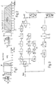
- FIG. 3 shows a block diagram of a recording circuit for the signals shown in FIGS. 1 and 2.
- the CVBS-PAL signal at terminal 1 is split into the luminance signal Y and the modulated color carrier F in the isolating stage 2.
- Y passes via the sub-pre-emphasis stage 3, the main pre-emphasis stage 4 and the amplitude limiter 5 to the FM modulator 6, which delivers the modulated image carrier BT to the adder stage 8 via the amplifier 7.
- the color carrier F with the frequency f1 is fed to the converter 10 via the bandpass 9 with a pass band of 4.43 ⁇ 0.6-0.8 MHz.
- the line synchronizing pulses are separated from Y in the separation stage 11 and converted in the converter 12 to the frequency f3 of the mixed carrier M1.
- the mixed carrier M1 passes through the high-pass filter 13 to the other input of the converter 10.
- the color carrier F is converted to the color carrier Fm with the frequency f2, which passes through the low-pass filter 14 to the other input of the adder 8.
- the adder 8 supplies the signal Fm + BT according to FIG. 1, which is recorded with the heads K1 on the magnetic tape T.
- the CVBS signal at terminal 1 is also fed to the MPEG encoder 15, which generates the digital image signal with 6 Mbit and a bandwidth of 3 MHz at its output.
- the signal can also have a larger bandwidth of, for example, 15 Mbit with an HDTV signal.
- This signal is fed to the channel encoder 16, which effects a modulation which is advantageous for the recording.
- This results in the signal according to FIG. 2 with a total bandwidth of 9.7 MHz. 2 reaches the adder stage 17, in which the two sound carriers T1, T2 frequency-modulated with sound signals are added.
- This combined signal with the frequency spectrum according to Fig. 2 reaches the heads K2 via the amplifier 18 and is thus recorded on the magnetic tape T.
- FIG. 4 shows the corresponding playback circuit for the recording circuit according to FIG. 3.
- the modulated image carrier BT reaches the FM demodulator 26 via the delay stage 24 and the amplitude limiter 25, which provides the luminance signal Y.
- Y reaches the terminal 29 via the low-pass filter 27 with a cut-off frequency of approximately 5 MHz and the deemphasis stage 28.
- the color carrier Fm also reaches the converter 31 via the low-pass filter 30 with a cut-off frequency of approximately 0.7 MHz the isolating stage 32, which supplies line frequency pulses with the frequency fH to the converter 33.
- the converter 33 supplies the mixing carrier M1 with the frequency f3, which passes through the low-pass filter 34 to the other input of the converter 31.
- the converter 31 supplies the color carrier F with the frequency f1, which reaches the terminal 37 via the bandpass 35.
- the composite signal is formed from Y and F, which is available at terminal 39 for image reproduction.
- the signal according to FIG. 2 is scanned with the heads K2. From the output of the switch 40, which switches between the heads K2 in tracks, the two sound carriers T1, T2 are evaluated with the bandpass filter 41 and fed to the FM demodulator 42. The sound signals NF1 and NF2 obtained in this way are available at terminals 50, 51.
- the digital MPEG signal according to FIG. 2 is evaluated frequency-selectively with the low-pass filter 45 and fed to the channel decoder 48. The digital output signal of the decoder 48 reaches the MPEG decoder 43, which again supplies an analog CVBS signal at the terminal 49.
- track A for the VHS signal according to FIG. 1 extends over the entire track width, but only over the lower lying magnetic layer S2.
- Track B for the signal according to FIG. 2 also extends over the entire track width, but only over the upper magnetic layer S1.
- the track B through the heads K2 is narrower than the track A and extends only over the upper magnetic layer S1.
- track A extends over the entire track width and the entire magnetic layer So, while track B also extends over the entire magnetic layer So, but as in FIG. 6 is narrower than track A.
- This solution has the following advantage : On the one hand, track A remains in both the lower magnetic layer S2 and the upper magnetic layer S1, which is advantageous for the signal-to-noise ratio. 2 in track B can, however, be recorded, deleted and re-recorded independently of the signal in track A. This stored position of track B in track A makes it possible to change the signal in track B as often as required without influencing the signal in track A. This is e.g. advantageous for recording a new image signal or for dubbing.
- the analog VHS picture signal in track A according to FIG. 1 and the digital picture signal in track B according to FIG. 2 can represent the same recording, ie the same film. However, they can also be signals independent of one another, represent different recordings or also contain the partial signals or differential signals of an HDTV signal or stereo image signal.
- the digital image signal is preferably a digital signal which is compressed and reduced in redundancy and in information. By pre-processing the signal in this way, the required recording bandwidth can be considerably reduced, in particular to a value of 6 Mbit corresponding to a bandwidth of 3 MHz or 15 Mbit for an HDTV signal corresponding to a bandwidth of 7.5 MHz.
- the digital signal according to FIG. 2 in track B in the upper magnetic layer S1 can also be a PCM audio signal.
- the broadband signal according to FIG. 2 recorded in the upper layer S1 with the magnetic heads K2 can also represent an HDTV signal. Then the signal according to FIG. 2 preferably has the full bandwidth of 2.3-12 MHz and not the reduced bandwidth C described. The signal recorded with K2 according to FIG. 2 preferably has twice the bandwidth of the layer S2 with the heads K1 recorded signal according to FIG. 1.
- the helper signal is completely eliminated when the VHS signal is recorded in the lower magnetic layer by black keying or gray keying.
- the helper signal thus eliminated in the VHS signal is, however, recorded with a second magnetic head in the upper layer of the magnetic tape and is thus available for high-quality PAL Plus playback with 16: 9 picture format and full number of lines.
- the VHS signal is recorded with the first magnetic head in a lower layer of the magnetic tape.
- the azimuth damping caused by the different azimuth angles of the two heads of the lower and upper magnetic layer is effective in this frequency range. For example, if the heads for the recording of the VHS signal in the lower magnetic layer have an azimuth angle of ⁇ 6 ° and the heads for the recording of the helper signal in the upper magnetic layer have an azimuth angle of ⁇ 30 °, crosstalk is also caused by the azimuth damping Signals from the two magnetic layers largely avoided. Below the frequency range of the carrier modulated with the helper signal in the upper magnetic layer, frequency-modulated sound carriers can additionally be recorded with sound signals.
- the recorder thus enables the separate recording and separate evaluation of a total of four signals, namely the image carrier frequency-modulated with the luminance signal and the frequency-reduced color under color carrier in the lower magnetic layer and the additional carrier modulated with the helper signal as well as further sound carriers in the upper magnetic layer .
- a particularly high signal-to-noise ratio is achieved for the helper signal. This is due to the fact that on the one hand a large frequency range is available for the helper signal and thus a large frequency deviation is possible and on the other hand the recording can be carried out with full amplitude. Compared to previous recordings of the helper signal, the signal-to-noise ratio can be increased by a factor of about 4.
- the CVBS signal at terminal 1 is separated with the comb filter 2 into the luminance signal Y and the color carrier F.
- Y is modulated in the FM modulator 6 on an image carrier BT in frequency modulation, which reaches the adder 8.
- the color carrier F with the frequency f1 of 4.43 MHz is converted in the frequency converter 10 to a lower frequency f2 of 626 kHz.
- the resulting modified color carrier Fm also called color under carrier, also arrives at the adder stage 8.
- the output signal of the adder stage 8, ie BT + Fm arrives via the switch 60 in the position shown on the first magnetic head K1 with a gap width of 0.9 ⁇ m and is recorded there on the magnetic tape T.
- two magnetic heads K1 are arranged on a rotating head drum.
- the color carrier F also reaches the FM modulator 62, which generates a carrier THS frequency-modulated with F.
- This carrier is evaluated with the bandpass 63 and fed to the switch 64.
- the output of the switch 64 is connected to the input of the adder 65, to which two sound carriers T1, T2 frequency-modulated with sound signals are also fed.
- the output signal of the adder 65 reaches the second magnetic head K2 with a gap width of 0.2 ⁇ m and is recorded on the same tracks as the signal of the magnetic head K1 on the magnetic tape T.
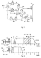
- FIG. 9 explains how the actual VHS signal and the helper signal are recorded.
- the switches 60, 64 are in the upper position during the duration of the actual VHS signal without a helper signal, that is to say during approximately 432 lines of an image.
- the VHS signal of these 432 lines is then recorded in a known manner with K1.
- the input of the adder 65 is grounded to the switch 64 since there is no helper signal during these lines.
- the sound carriers T1, T2 are recorded with K2.
- the recording with K1 takes place with an azimuth angle A1 of ⁇ 6 °.
- the color carrier F modulated onto the carrier THS and in turn modulated with the helper signal has a frequency swing H1 of ⁇ 1.2 MHz, while the carrier THS modulated with the color carrier has a frequency swing H2 of 3.6 MHz (6.4 MHz - 10.0 MHz ) having.
- the entire frequency spectrum of the carrier THS modulated with the helper signal extends from 2.3 to 12 MHz.
- the recording with K2 takes place with an azimuth angle A2 of ⁇ 30 °.
- the signals recorded in this way can be separated and recovered without mutual interference.
- the head K1 then supplies the signal BT + Fm for a pure VHS playback with 432 lines, e.g. for a 16: 9 picture on a 4: 3 screen.
- the helper signal also recorded does not cause any interference in the black bars, because this signal is recorded with K2 only in the upper magnetic layer S1 and is not read by the head K1 with the larger gap width of 0.9 ⁇ m.
- the two sound carriers T1, T2 are read with K2 from the upper magnetic layer S1 and are available for sound reproduction.
- the carrier THS can be scanned from the tape T with K2.
- the color carrier F modulated with the helper signal is then recovered by demodulation adapted to the modulator 62.
- the helper signal can be recovered to produce a high-quality 16: 9 image with a full number of lines.
Landscapes
- Engineering & Computer Science (AREA)
- Multimedia (AREA)
- Signal Processing (AREA)
- Recording Or Reproducing By Magnetic Means (AREA)
- Television Signal Processing For Recording (AREA)
- Signal Processing For Digital Recording And Reproducing (AREA)
Applications Claiming Priority (4)
| Application Number | Priority Date | Filing Date | Title |
|---|---|---|---|
| DE4200222 | 1992-01-08 | ||
| DE19924200222 DE4200222A1 (de) | 1992-01-08 | 1992-01-08 | Videorecorder |
| DE19924200434 DE4200434A1 (de) | 1992-01-10 | 1992-01-10 | Videorecorder fuer ein pal-plus-signal |
| DE4200434 | 1992-01-10 |
Publications (2)
| Publication Number | Publication Date |
|---|---|
| EP0558821A2 true EP0558821A2 (fr) | 1993-09-08 |
| EP0558821A3 EP0558821A3 (en) | 1993-09-29 |
Family
ID=25910834
Family Applications (1)
| Application Number | Title | Priority Date | Filing Date |
|---|---|---|---|
| EP19920122131 Withdrawn EP0558821A3 (en) | 1992-01-08 | 1992-12-30 | Videorecorder |
Country Status (4)
| Country | Link |
|---|---|
| EP (1) | EP0558821A3 (fr) |
| JP (1) | JPH0614343A (fr) |
| KR (1) | KR930016946A (fr) |
| CA (1) | CA2086734A1 (fr) |
Cited By (3)
| Publication number | Priority date | Publication date | Assignee | Title |
|---|---|---|---|---|
| EP0573246A3 (en) * | 1992-06-05 | 1994-09-14 | Matsushita Electric Industrial Co Ltd | A magnetic recording/reproducing apparatus for recording and reproducing a video signal added with a helper signal |
| EP0896323A3 (fr) * | 1997-08-06 | 1999-08-11 | Victor Company Of Japan, Limited | Appareil et méthode d'enregistrement magnétique et milieu d'enregistrement magnétique |
| WO2003039144A3 (fr) * | 2001-11-01 | 2003-08-14 | A4S Technologies Inc | Systeme de surveillance a distance |
Families Citing this family (1)
| Publication number | Priority date | Publication date | Assignee | Title |
|---|---|---|---|---|
| US6104862A (en) * | 1994-12-19 | 2000-08-15 | Hitachi, Ltd. | Video signal recording and reproducing apparatus compatible with analog and digital video signal recording and reproducing |
Family Cites Families (4)
| Publication number | Priority date | Publication date | Assignee | Title |
|---|---|---|---|---|
| US4679097A (en) * | 1983-11-30 | 1987-07-07 | Matsushita Electric Industrial Co., Ltd. | Method of recording and reproducing video and audio signals on a magnetic tape |
| JPS6113364U (ja) * | 1984-06-22 | 1986-01-25 | 株式会社日立製作所 | 磁気記録再生装置 |
| US4758903A (en) * | 1984-11-22 | 1988-07-19 | Hitachi, Ltd. | Apparatus for recording and reproducing video signal and digital signal other than video signal |
| DE4014832A1 (de) * | 1990-05-09 | 1991-11-14 | Thomson Brandt Gmbh | Videorecorder mit verbesserter tonaufzeichnung |
-
1992
- 1992-12-30 EP EP19920122131 patent/EP0558821A3/en not_active Withdrawn
-
1993
- 1993-01-05 CA CA002086734A patent/CA2086734A1/fr not_active Abandoned
- 1993-01-07 JP JP5001056A patent/JPH0614343A/ja active Pending
- 1993-01-08 KR KR1019930000161A patent/KR930016946A/ko not_active Withdrawn
Cited By (4)
| Publication number | Priority date | Publication date | Assignee | Title |
|---|---|---|---|---|
| EP0573246A3 (en) * | 1992-06-05 | 1994-09-14 | Matsushita Electric Industrial Co Ltd | A magnetic recording/reproducing apparatus for recording and reproducing a video signal added with a helper signal |
| EP0896323A3 (fr) * | 1997-08-06 | 1999-08-11 | Victor Company Of Japan, Limited | Appareil et méthode d'enregistrement magnétique et milieu d'enregistrement magnétique |
| WO2003039144A3 (fr) * | 2001-11-01 | 2003-08-14 | A4S Technologies Inc | Systeme de surveillance a distance |
| US7272179B2 (en) | 2001-11-01 | 2007-09-18 | Security With Advanced Technology, Inc. | Remote surveillance system |
Also Published As
| Publication number | Publication date |
|---|---|
| JPH0614343A (ja) | 1994-01-21 |
| CA2086734A1 (fr) | 1993-07-09 |
| EP0558821A3 (en) | 1993-09-29 |
| KR930016946A (ko) | 1993-08-30 |
Similar Documents
| Publication | Publication Date | Title |
|---|---|---|
| DE2917022C2 (fr) | ||
| DE68923518T2 (de) | Farbvideosignalverarbeitungsvorrichtung. | |
| DE68927796T2 (de) | Verfahren und Gerät zur Übertragung von Videosignalen | |
| DE68916295T2 (de) | Vorrichtung zur magnetischen Aufzeichnung und Wiedergabe. | |
| DE3642217C2 (fr) | ||
| WO1991016790A1 (fr) | Magnetoscope avec enregistrement ameliore des couleurs | |
| EP0558821A2 (fr) | Enregistreur vidéo | |
| DE3201451C2 (de) | "Informationswiedergabevorrichtung" | |
| DE3314782C2 (fr) | ||
| DE69027473T2 (de) | Vorrichtung zum Verarbeiten eins Video-Komponentensignals mit breitbandiger Luminanzkomponente | |
| DE2636571A1 (de) | Geraet zum aufzeichnen eines farb- videosignals | |
| DE4027388A1 (de) | Videorecorder fuer ein fernsehsignal mit einem zusatzsignal | |
| DE4134536C2 (de) | Verfahren und Vorrichtung zum Aufzeichnen von Videosignalen | |
| DE69521259T2 (de) | Vorrichtung zur magnetischen Aufnahme und Wiedergabe vom Typ mit spiralenförmiger Abtastung | |
| DE4127541C2 (de) | Schaltung und Verfahren zum Aufzeichnen eines Luminanzsignals | |
| DE3730135A1 (de) | Bandaufzeichnungssystem | |
| DE4012963A1 (de) | Videorecorder mit verbesserter farbaufzeichnung | |
| EP0587631B1 (fr) | Magnetoscope | |
| DE4200222A1 (de) | Videorecorder | |
| DE4233356A1 (de) | Videorecorder für ein PAL-Plus-System | |
| DE4200434A1 (de) | Videorecorder fuer ein pal-plus-signal | |
| WO1991016792A1 (fr) | Magnetoscope avec enregistrement ameliore des couleurs | |
| AT399070B (de) | Einrichtung zum wiedergeben und verarbeiten eines videosignales und schaltungsausbildung für eine solche einrichtung | |
| DE2342167A1 (de) | Schaltungsanordnung zur ableitung von farbfernsehsignalen und geraet zur aufzeichnung und/oder wiedergabe der signale | |
| DE69228437T2 (de) | Vorrichtung zum Verarbeiten eines Videosignals |
Legal Events
| Date | Code | Title | Description |
|---|---|---|---|
| PUAI | Public reference made under article 153(3) epc to a published international application that has entered the european phase |
Free format text: ORIGINAL CODE: 0009012 |
|
| PUAL | Search report despatched |
Free format text: ORIGINAL CODE: 0009013 |
|
| AK | Designated contracting states |
Kind code of ref document: A2 Designated state(s): DE ES FR GB IT |
|
| AK | Designated contracting states |
Kind code of ref document: A3 Designated state(s): DE ES FR GB IT |
|
| STAA | Information on the status of an ep patent application or granted ep patent |
Free format text: STATUS: THE APPLICATION IS DEEMED TO BE WITHDRAWN |
|
| 18D | Application deemed to be withdrawn |
Effective date: 19940330 |