EP0558826A1 - Verfahren zur Herstellung eines Deckenelementes oder einer Rippedecken und Wärmedämmplatte für Deckenelementen - Google Patents
Verfahren zur Herstellung eines Deckenelementes oder einer Rippedecken und Wärmedämmplatte für Deckenelementen Download PDFInfo
- Publication number
- EP0558826A1 EP0558826A1 EP92200613A EP92200613A EP0558826A1 EP 0558826 A1 EP0558826 A1 EP 0558826A1 EP 92200613 A EP92200613 A EP 92200613A EP 92200613 A EP92200613 A EP 92200613A EP 0558826 A1 EP0558826 A1 EP 0558826A1
- Authority
- EP
- European Patent Office
- Prior art keywords
- sheet
- shaped
- floor
- concrete
- leg
- Prior art date
- Legal status (The legal status is an assumption and is not a legal conclusion. Google has not performed a legal analysis and makes no representation as to the accuracy of the status listed.)
- Granted
Links
- 239000011810 insulating material Substances 0.000 title claims abstract description 26
- 238000004519 manufacturing process Methods 0.000 title claims abstract description 9
- 238000009416 shuttering Methods 0.000 claims abstract description 24
- 238000000034 method Methods 0.000 claims abstract description 14
- 230000000284 resting effect Effects 0.000 claims description 4
- 239000006260 foam Substances 0.000 claims 1
- 239000012774 insulation material Substances 0.000 claims 1
- 238000009413 insulation Methods 0.000 description 13
- 239000004793 Polystyrene Substances 0.000 description 7
- 229920002223 polystyrene Polymers 0.000 description 7
- 238000005520 cutting process Methods 0.000 description 4
- 238000009415 formwork Methods 0.000 description 3
- 238000010276 construction Methods 0.000 description 2
- 230000015572 biosynthetic process Effects 0.000 description 1
- 238000011161 development Methods 0.000 description 1
- 230000018109 developmental process Effects 0.000 description 1
- 239000011796 hollow space material Substances 0.000 description 1
- 239000003562 lightweight material Substances 0.000 description 1
- 239000000463 material Substances 0.000 description 1
- 239000004570 mortar (masonry) Substances 0.000 description 1
- 230000000717 retained effect Effects 0.000 description 1
- 239000002699 waste material Substances 0.000 description 1
Images
Classifications
-
- E—FIXED CONSTRUCTIONS
- E04—BUILDING
- E04B—GENERAL BUILDING CONSTRUCTIONS; WALLS, e.g. PARTITIONS; ROOFS; FLOORS; CEILINGS; INSULATION OR OTHER PROTECTION OF BUILDINGS
- E04B5/00—Floors; Floor construction with regard to insulation; Connections specially adapted therefor
- E04B5/16—Load-carrying floor structures wholly or partly cast or similarly formed in situ
- E04B5/32—Floor structures wholly cast in situ with or without form units or reinforcements
- E04B5/36—Floor structures wholly cast in situ with or without form units or reinforcements with form units as part of the floor
Definitions
- the invention relates to a method for producing a floor part which is used to be combined with several floor parts to form a concrete floor, which floor is provided on the downward facing surfaces with thermally insulating material as an encasing covering, and which concrete floor comprises a concrete slab which is provided on the underside with concrete ribs at regular intervals, and also a sheet of a thermally insulating material for use in one of the methods for producing a floor part or a concrete floor.
- a concrete floor comprising a concrete slab provided at regular intervals on the underside with concrete ribs which can assume all kinds of shapes, which floor is provided on the underside with a layer of thermally insulating material, is generally known.
- the most commonly used concrete rib has been one in which the cross-section corresponds to an inverted T-shape.
- Developments in building methods have led to more and more concrete ribs now being used with other cross-sections, depending on the spans and weights of floors.
- These floors are used as ground floors, also provided with a so-called encasing covering, and made of a thermally insulating material.
- Such ribbed floors can be assembled on the building structure from a number of concrete ribs and parts of a thermally insulating material placed between said ribs, following which concrete is poured on the ribs and the parts placed there, said parts also serving as formwork.
- the ribs are preferably also encased with thermally insulating material.
- the essentially sheet-type parts are generally provided on one side of each part with a flange-shaped extension which is pushed around the adjacent concrete rib during the placing of a sheet-type part.
- Another known system is that in which concrete ribs with an inverted T-shaped cross-section are placed in the building structure at a certain distance from each other; C-shaped polystyrene sections abutting each other near the underside are then pushed around the flanges of the ribs projecting on either side of the ribs, following which the sheet-type elements to be placed between the ribs are laid on said sections.
- Such a system is known, for example from Dutch Patent Application 7,907,756 and Dutch Patent Application 8,006,287.
- Another known design for producing ribbed floors is that in which the ribs, at least the bottom parts of the ribs, are poured into a U-shaped polystyrene casing in the concrete factory.
- the good adhesion of polystyrene to the concrete produces a concrete rib in the case of which the sheet-type parts to be inserted in the building structure between the regularly spaced ribs can fully or partially find their bearing on the legs of the U-shaped casing of a concrete rib without said casing becoming detached.
- floor parts are prefabricated as completely as possible in the concrete factory and then combined in the building structure.
- the parts are composed of a concrete slab which near the underside is provided with one or more concrete ribs at certain intervals lying parallel to each other and forming a homogeneous unit with the slab.
- the parts are also already provided on all bottom faces with a thermally insulating material.
- Floor parts of inverted U-shaped cross-section are generally used, so that two legs of floor parts placed next to each other go against each other and are fixed to each other. This produces ribs made up of two legs of two successive U-shapes, in which the join takes place over a large vertical surface and this fixing is very strong.
- the seams which then have to be sealed between the ribs in the sheet-type part are smaller and consequently not so strong.
- a disadvantage in the case of all these known ribbed floors and methods for producing ribbed floors and floor parts is the great degree of dependence on the cross-sections of the concrete ribs and the great degree of dependence on insulation thicknesses, and thus insulation values. These limitations are caused by the usual uniformity of the cross-sections of the insulating casings of the concrete ribs. It has been found that, as soon as there is any departure from the usual cross-sections of these insulation forms, obtaining suitable forms becomes difficult because of the investment and labour-intensiveness, and it also usually leads to material loss.
- the object of the invention is a method for producing concrete ribbed floors or floor parts in which a ribbed floor of any desired shape or any desired cross-section can be assembled from several floor parts, while these floors or elements are provided with a thermal insulation layer of any desired thickness on the underside.
- Another object of the invention is to produce component parts of the thermal insulation layer so economically that as little waste as possible is also produced and transportation from the place of production to the destination can take place as economically as possible.
- a method for producing floor parts with which concrete ribbed floors can be assembled characterised in that an element is cut out of a flat or curved sheet of thermally insulating material of which the cross-section in the horizontal plane is essentially rectangular, and in which an element is first cut out from a side of the sheet in the lengthwise direction, which element is L-shaped when viewed in cross-section at right angles to the lengthwise direction, one leg of the L-shaped element being formed from a part of the height of the side of the sheet, in such a way that the end of the short leg coincides with the underside of the sheet, and the long leg of the L-shaped element being cut out of the inside of the sheet, with the result that a stop or recess remains near the top side of the sheet; in that the element cut in an L-shape is then taken out of the sheet, in that an element cut in an L-shape is then placed in such a way that one leg points upwards and the other leg outwards, and in that the reces
- U-shaped floor parts can also be produced by cutting out of each of the two opposite sides of the sheet in the lengthwise direction an element which, viewed in cross-section, is L-shaped at right angles to the lengthwise direction and then placing an L-shaped element on each side of the sheet under each of the recesses produced, one of the legs pointing upwards and the other leg downwards, and each of the recesses resting on one of the ends of one of the legs of one of the L-shaped insulating elements in such a way that the two L-shaped elements and the sheet form a part of a shuttering which together with remaining shuttering parts forms a shuttering, which shuttering is finally filled with concrete, so that after the concrete sets a floor element with a permanent casing of thermally insulating material is produced, so that what could be described as a U-shaped floor part is produced.
- the L-shaped insulating sections are set up in pairs in a U-formation, in such a way that concrete ribs are formed therein, at least the bottom part of said ribs being encased.
- the concrete is poured partially on the building structure and the concrete ribs are prefabricated
- the ribs are encased with the L-shaped insulating sections, in such a way that the latter abut each other in a U-shaped formation under and around the rib.
- a preferred embodiment here is a flange-shaped provision in the cross-section of the L-shapes on the inside of the end of the vertically disposed leg, as a result of which a good fixing of the L-shapes in the structure is obtained.
- the sheets can also be produced in a factory, after which the sheets with cut-out L-shaped elements are taken to the production place, where the floor parts or floors are produced. Due to the fact that the L-shaped parts fit in the sheets, the space during transportation can be used very economically. After the sheets have been used for producing floor parts or floors, in which case the L-shaped parts are taken out of the sheets and then processed in the desired structure, hollow spaces are left in the insulating covering. These spaces enclosed by insulating material will, however, also provide good thermal insulation. These spaces can be shut off or filled up with insulating material if desired. A good possibility is also to use these channels for cables or pipes and thermal insulation of said cables or pipes.
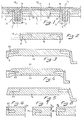
- Figure 1 shows a part of a concrete ribbed floor 1, comprising a concrete slab 2 and two ribs 3.
- the underside of the floor is provided with a thermally insulating casing, of which three sheets 4 of a thermally insulating material can be seen here.
- L-shaped elements 5 are cut out of each sheet 4 in the lengthwise direction of the sheet 4.
- the L-shaped element is L-shaped when viewed in cross-section at right angles to the lengthwise direction.
- One leg 7, generally the short leg, of the L-shaped element 5 is formed from a part of the height of the side 6 of the sheet 4, in such a way that the end of one leg 7 coincides with the underside 8 near the side of the sheet 4.
- the other leg 9, generally the long leg, of the L-shaped element 5 is cut out of the inside of the sheet 4.
- the L-shaped element is cut out of the sheet in such a way that the whole side 6 is not cut away, but a stop or recess 10 is left near the top side of the sheet 4.
- the L-shaped elements 5 are removed from the sheets 4, the L-shaped elements are then combined two by two to a U-shape, the U-shapes being placed at such a distance from each other that a sheet can be placed between two legs of successive U-shapes where the U-shapes have been taken out, in such a way that the two recesses 10 on either side of the sheet each rest on a leg 9 of one of the L-shaped elements 5.
- the U-shapes are placed at such a distance from each other that the underside of each sheet is placed in a tight fit between the legs of the two U-shapes.
- floor parts which can be L-shaped or U-shaped, depending on the use, can be produced in concrete factories.
- L-shaped parts can be made by dividing the floor according to the dashed lines 11 and 12 shown in Figure 1.
- U-shaped parts can also be formed by dividing the floor according to the dashed lines 11.
- the floor parts with casing can then be transported to the building structure and incorporated, following which the successive parts can be connected to each other using mortar. This is a method which is known per se.
- Figure 2 shows a sheet which is rectangular both in longitudinal section and in cross-section, in which an L-shaped element 5 is cut out of the sheet 4 on both sides.
- the L-shaped elements when cut away, regardless of the profiling of their cross-sections such as thicknesses, squareness and the like, come to lie completely nested in the sheet form.
- the dashed lines show how an L-shaped element can be removed from the polystyrene sheet and, unlike the situation shown in Figure 1, in which the longitudinal leg is placed vertically, the long leg is placed horizontally.
- dashed line 14 it is also shown in Figure 2 by dashed line 14 that such a sheet can also be cut curved out of, for example, a large block of polystyrene.
- the curved dashed line indicates that the sheet 4 is curved only at the underside. Due to the fact that in the cut-out position of the L-shaped elements these elements are nested in the sheet 4, the very compact structure of the sheets with the L-shapes of the thermally insulating material is a major advantage of this bulky lightweight material during transportation from the factory where the L-shaped sheets are made to the concrete factory.
- Figure 3 shows a curved sheet 34 in which L-shaped elements nested on either side are cut out.
- One of the L-shaped elements is taken out of the sheet 4 and turned into the position used to produce a concrete floor with thermally insulating casing provided on the underside.
- the sheet shown in Figure 3 and the L-shaped elements 35 cut out of it a concrete construction whose beams taper slightly downwards is obtained.
- Figure 4 shows yet another possible method of cutting L-shaped elements 45 out of a curved sheet 44, the recess 40 being slightly shortened so that it can be adapted to the width of the top side of the vertically placed L-shaped leg. This excess length can be left intact if desired and used for concrete ribs already prefabricated in the factory, which ribs are already provided with a casing. As indicated by dashed lines 43, the curvature can be made double, but the nesting of several sheets on top of one another is retained, so that several of these sheets can be cut in a simple manner from a large block of polystyrene.
- Figure 5 shows in cross-section a sheet 54, which is trapezoidal in cross-section.
- L-shaped elements 55 are cut out of both sides, which elements can interact with the sheets 54 after said L-shaped elements have been removed from them and the sheets are placed on either side with the recess 50 on the end of one of the legs 59 of an L-shaped element 55.
- Figures 6, 7 and 8 then show in vertical section a part of a sheet 64, 74, 84, from which other kinds of L-shaped elements 65, 75 and 85 are cut.
- the L-shaped element 65 which is shown nested in the sheet 64 has two flange-shaped extensions 66, 67. These flanges 66, 67 are formed in such a way that, after the L-shaped elements 65 have been removed from the sheets 64 and the L-shaped elements 65 have been placed in the correct position, the flange-shaped projections 66 and 67 can interact with the sheet.
- the projection 67 then just fits into the hollow space which has been produced in the sheet after the removal of the L-shaped element 65. A better seal of the air channel is obtained in this way, and the support and connection to the sheet of the L-shaped elements is also stronger.
- the L-shaped element 75 has flanges 76 and 77, in which the flange 77 can be used to hang the L-shaped element on a prefabricated concrete rib, following which the sheets 74 with the recess 70 can be placed on the L-shaped elements 75 which are slid around the beams.
- Figure 8 shows yet another possible way of cutting the L-shaped element 85 out of a sheet 84. As shown in the drawings, it is possible according to the invention to cut the L-shaped element out of the sheets in different ways.
Landscapes
- Engineering & Computer Science (AREA)
- Architecture (AREA)
- Physics & Mathematics (AREA)
- Electromagnetism (AREA)
- Civil Engineering (AREA)
- Structural Engineering (AREA)
- Building Environments (AREA)
- Floor Finish (AREA)
- Vehicle Interior And Exterior Ornaments, Soundproofing, And Insulation (AREA)
- Heating, Cooling, Or Curing Plastics Or The Like In General (AREA)
- Tyre Moulding (AREA)
Priority Applications (4)
| Application Number | Priority Date | Filing Date | Title |
|---|---|---|---|
| DK92200613.5T DK0558826T3 (da) | 1992-03-03 | 1992-03-03 | Fremgangsmåde til fremstilling af et dækelement samt isoleringsplade til dækelementer |
| AT92200613T ATE130069T1 (de) | 1992-03-03 | 1992-03-03 | Verfahren zur herstellung eines deckenelementes oder einer rippedecken und wärmedämmplatte für deckenelementen. |
| DE69205965T DE69205965T2 (de) | 1992-03-03 | 1992-03-03 | Verfahren zur Herstellung eines Deckenelementes oder einer Rippedecken und Wärmedämmplatte für Deckenelementen. |
| EP92200613A EP0558826B1 (de) | 1992-03-03 | 1992-03-03 | Verfahren zur Herstellung eines Deckenelementes oder einer Rippedecken und Wärmedämmplatte für Deckenelementen |
Applications Claiming Priority (1)
| Application Number | Priority Date | Filing Date | Title |
|---|---|---|---|
| EP92200613A EP0558826B1 (de) | 1992-03-03 | 1992-03-03 | Verfahren zur Herstellung eines Deckenelementes oder einer Rippedecken und Wärmedämmplatte für Deckenelementen |
Publications (2)
| Publication Number | Publication Date |
|---|---|
| EP0558826A1 true EP0558826A1 (de) | 1993-09-08 |
| EP0558826B1 EP0558826B1 (de) | 1995-11-08 |
Family
ID=8210465
Family Applications (1)
| Application Number | Title | Priority Date | Filing Date |
|---|---|---|---|
| EP92200613A Expired - Lifetime EP0558826B1 (de) | 1992-03-03 | 1992-03-03 | Verfahren zur Herstellung eines Deckenelementes oder einer Rippedecken und Wärmedämmplatte für Deckenelementen |
Country Status (4)
| Country | Link |
|---|---|
| EP (1) | EP0558826B1 (de) |
| AT (1) | ATE130069T1 (de) |
| DE (1) | DE69205965T2 (de) |
| DK (1) | DK0558826T3 (de) |
Cited By (2)
| Publication number | Priority date | Publication date | Assignee | Title |
|---|---|---|---|---|
| AU704885B2 (en) * | 1996-10-11 | 1999-05-06 | Jacek Blum | Flooring system |
| EP1972735A1 (de) | 2007-03-21 | 2008-09-24 | J.G. Van Arnhem B.V. | System von Bodenelementen und Verfahren zur Herstellung der Bodenelemente sowie Verfahren zur Herstellung einer Bodenkonstruktion mit den Bodenelementen |
Families Citing this family (7)
| Publication number | Priority date | Publication date | Assignee | Title |
|---|---|---|---|---|
| CN100564748C (zh) * | 2003-05-06 | 2009-12-02 | 邱则有 | 一种现浇钢筋砼空心板 |
| CN100549315C (zh) * | 2003-08-04 | 2009-10-14 | 邱则有 | 一种现浇砼用空腔模壳构件 |
| CN100537931C (zh) * | 2003-09-15 | 2009-09-09 | 邱则有 | 一种现浇砼用轻质胎模构件 |
| CN1280500C (zh) * | 2003-09-26 | 2006-10-18 | 邱则有 | 一种空腔模壳构件 |
| CN100516402C (zh) * | 2003-10-01 | 2009-07-22 | 邱则有 | 一种模壳构件 |
| CN100535295C (zh) * | 2003-10-01 | 2009-09-02 | 邱则有 | 一种模壳构件 |
| CN102185464B (zh) * | 2011-03-28 | 2014-03-12 | 中国电力科学研究院 | 一种用于高压直流换流阀的绝缘梁 |
Citations (4)
| Publication number | Priority date | Publication date | Assignee | Title |
|---|---|---|---|---|
| FR2166335A1 (en) * | 1972-01-05 | 1973-08-17 | Sattanino Jean Pierre | Prefabricated flooring components - using profiled sections of insulating materials in conjunction with cast concrete |
| DE2653828A1 (de) * | 1975-11-28 | 1977-06-08 | Traeullit Ab | Giessform zur bildung einer balkenlage |
| NL8006287A (nl) * | 1980-01-17 | 1981-08-17 | Arnhem Bv J G | Betonvloerconstructie, die aan de onderzijde is geisoleerd en daarbij gebruikte elementen uit isolatiemateriaal. |
| NL8002014A (nl) * | 1980-04-03 | 1981-11-02 | Omnia Adviesbureau B V | Werkwijze voor het vervaardigen van een isolerende vloer. |
-
1992
- 1992-03-03 AT AT92200613T patent/ATE130069T1/de not_active IP Right Cessation
- 1992-03-03 EP EP92200613A patent/EP0558826B1/de not_active Expired - Lifetime
- 1992-03-03 DK DK92200613.5T patent/DK0558826T3/da active
- 1992-03-03 DE DE69205965T patent/DE69205965T2/de not_active Expired - Fee Related
Patent Citations (4)
| Publication number | Priority date | Publication date | Assignee | Title |
|---|---|---|---|---|
| FR2166335A1 (en) * | 1972-01-05 | 1973-08-17 | Sattanino Jean Pierre | Prefabricated flooring components - using profiled sections of insulating materials in conjunction with cast concrete |
| DE2653828A1 (de) * | 1975-11-28 | 1977-06-08 | Traeullit Ab | Giessform zur bildung einer balkenlage |
| NL8006287A (nl) * | 1980-01-17 | 1981-08-17 | Arnhem Bv J G | Betonvloerconstructie, die aan de onderzijde is geisoleerd en daarbij gebruikte elementen uit isolatiemateriaal. |
| NL8002014A (nl) * | 1980-04-03 | 1981-11-02 | Omnia Adviesbureau B V | Werkwijze voor het vervaardigen van een isolerende vloer. |
Cited By (2)
| Publication number | Priority date | Publication date | Assignee | Title |
|---|---|---|---|---|
| AU704885B2 (en) * | 1996-10-11 | 1999-05-06 | Jacek Blum | Flooring system |
| EP1972735A1 (de) | 2007-03-21 | 2008-09-24 | J.G. Van Arnhem B.V. | System von Bodenelementen und Verfahren zur Herstellung der Bodenelemente sowie Verfahren zur Herstellung einer Bodenkonstruktion mit den Bodenelementen |
Also Published As
| Publication number | Publication date |
|---|---|
| EP0558826B1 (de) | 1995-11-08 |
| DE69205965D1 (de) | 1995-12-14 |
| ATE130069T1 (de) | 1995-11-15 |
| DK0558826T3 (da) | 1995-12-11 |
| DE69205965T2 (de) | 1996-04-11 |
Similar Documents
| Publication | Publication Date | Title |
|---|---|---|
| US6880304B1 (en) | Structural thermal framing and panel system for assembling finished or unfinished walls with multiple panel combinations for poured and nonpoured walls | |
| US6003278A (en) | Monolithic stud form for concrete wall production | |
| US7810293B2 (en) | Multiple layer polymer foam and concrete system for forming concrete walls, panels, floors, and decks | |
| US4454702A (en) | Building construction and method of constructing same | |
| FI82520B (fi) | Prefabricerad modul foer anvaendning vid husbyggnad. | |
| US3307304A (en) | Composite structural systems | |
| US6494004B1 (en) | Self jigging concrete wall structure and method of construction | |
| US4363200A (en) | Pre-cast building element and method | |
| EP0558826B1 (de) | Verfahren zur Herstellung eines Deckenelementes oder einer Rippedecken und Wärmedämmplatte für Deckenelementen | |
| EP0061100B1 (de) | Vorgefertigte Strukturen, Verfahren zur Herstellung und ihre Anwendung in industriellen Gebäuden | |
| EP0033942A2 (de) | Verfahren zum Herstellen von Ortbetonwänden mit darin eingebetteter Isolation | |
| US5146726A (en) | Composite building system and method of manufacturing same and components therefor | |
| EP1146179A2 (de) | Vorbewehrtes Schalungsbaupanel | |
| AU570293B2 (en) | Building construction formed of module elements (especially walls) | |
| RU2184816C1 (ru) | Сборно-монолитный железобетонный каркас многоэтажного здания "казань-1000" | |
| JP2001065094A (ja) | コンクリート床の構築に用いるコンクリート型枠 | |
| WO2012060863A2 (en) | Wall panel construction and method for in situ assembly | |
| JP3071771B2 (ja) | ボイドスラブの構築方法 | |
| RU34951U1 (ru) | Несущая стена здания | |
| SU1131984A1 (ru) | Сборна многопустотна панель перекрытий | |
| CA1214657A (en) | Prefabricated structures, method for their manufacture and their use in the building industry | |
| JP2961083B2 (ja) | コンクリート型枠構造 | |
| JP2999411B2 (ja) | 壁または基礎構築用セパレータおよびそれを使用したコンクリート型枠構造 | |
| KR20010084934A (ko) | Tilt-up 벽판의 단열 시공 기술 | |
| JP3334944B2 (ja) | 建物の構築方法 |
Legal Events
| Date | Code | Title | Description |
|---|---|---|---|
| PUAI | Public reference made under article 153(3) epc to a published international application that has entered the european phase |
Free format text: ORIGINAL CODE: 0009012 |
|
| AK | Designated contracting states |
Kind code of ref document: A1 Designated state(s): AT BE DE DK FR GB IT LU NL |
|
| 17P | Request for examination filed |
Effective date: 19930810 |
|
| 17Q | First examination report despatched |
Effective date: 19941111 |
|
| GRAA | (expected) grant |
Free format text: ORIGINAL CODE: 0009210 |
|
| ITF | It: translation for a ep patent filed | ||
| AK | Designated contracting states |
Kind code of ref document: B1 Designated state(s): AT BE DE DK FR GB IT LU NL |
|
| REF | Corresponds to: |
Ref document number: 130069 Country of ref document: AT Date of ref document: 19951115 Kind code of ref document: T |
|
| REG | Reference to a national code |
Ref country code: DK Ref legal event code: T3 |
|
| REF | Corresponds to: |
Ref document number: 69205965 Country of ref document: DE Date of ref document: 19951214 |
|
| ET | Fr: translation filed | ||
| PLBE | No opposition filed within time limit |
Free format text: ORIGINAL CODE: 0009261 |
|
| STAA | Information on the status of an ep patent application or granted ep patent |
Free format text: STATUS: NO OPPOSITION FILED WITHIN TIME LIMIT |
|
| 26N | No opposition filed | ||
| PGFP | Annual fee paid to national office [announced via postgrant information from national office to epo] |
Ref country code: AT Payment date: 20010326 Year of fee payment: 10 |
|
| REG | Reference to a national code |
Ref country code: GB Ref legal event code: IF02 |
|
| PG25 | Lapsed in a contracting state [announced via postgrant information from national office to epo] |
Ref country code: AT Free format text: LAPSE BECAUSE OF NON-PAYMENT OF DUE FEES Effective date: 20020303 |
|
| PGFP | Annual fee paid to national office [announced via postgrant information from national office to epo] |
Ref country code: GB Payment date: 20030220 Year of fee payment: 12 |
|
| PGFP | Annual fee paid to national office [announced via postgrant information from national office to epo] |
Ref country code: FR Payment date: 20030225 Year of fee payment: 12 |
|
| PGFP | Annual fee paid to national office [announced via postgrant information from national office to epo] |
Ref country code: DK Payment date: 20030311 Year of fee payment: 12 |
|
| PGFP | Annual fee paid to national office [announced via postgrant information from national office to epo] |
Ref country code: LU Payment date: 20030321 Year of fee payment: 12 |
|
| PG25 | Lapsed in a contracting state [announced via postgrant information from national office to epo] |
Ref country code: LU Free format text: LAPSE BECAUSE OF NON-PAYMENT OF DUE FEES Effective date: 20040303 Ref country code: GB Free format text: LAPSE BECAUSE OF NON-PAYMENT OF DUE FEES Effective date: 20040303 |
|
| PG25 | Lapsed in a contracting state [announced via postgrant information from national office to epo] |
Ref country code: DK Free format text: LAPSE BECAUSE OF NON-PAYMENT OF DUE FEES Effective date: 20040331 |
|
| PGFP | Annual fee paid to national office [announced via postgrant information from national office to epo] |
Ref country code: DE Payment date: 20040503 Year of fee payment: 13 |
|
| PGFP | Annual fee paid to national office [announced via postgrant information from national office to epo] |
Ref country code: BE Payment date: 20040506 Year of fee payment: 13 |
|
| GBPC | Gb: european patent ceased through non-payment of renewal fee | ||
| PG25 | Lapsed in a contracting state [announced via postgrant information from national office to epo] |
Ref country code: FR Free format text: LAPSE BECAUSE OF NON-PAYMENT OF DUE FEES Effective date: 20041130 |
|
| REG | Reference to a national code |
Ref country code: FR Ref legal event code: ST |
|
| PG25 | Lapsed in a contracting state [announced via postgrant information from national office to epo] |
Ref country code: IT Free format text: LAPSE BECAUSE OF NON-PAYMENT OF DUE FEES;WARNING: LAPSES OF ITALIAN PATENTS WITH EFFECTIVE DATE BEFORE 2007 MAY HAVE OCCURRED AT ANY TIME BEFORE 2007. THE CORRECT EFFECTIVE DATE MAY BE DIFFERENT FROM THE ONE RECORDED. Effective date: 20050303 |
|
| PG25 | Lapsed in a contracting state [announced via postgrant information from national office to epo] |
Ref country code: BE Free format text: LAPSE BECAUSE OF NON-PAYMENT OF DUE FEES Effective date: 20050331 |
|
| PGFP | Annual fee paid to national office [announced via postgrant information from national office to epo] |
Ref country code: NL Payment date: 20050331 Year of fee payment: 14 |
|
| BERE | Be: lapsed |
Owner name: J.G. *VAN ARNHEM B.V. Effective date: 20050331 |
|
| PG25 | Lapsed in a contracting state [announced via postgrant information from national office to epo] |
Ref country code: DE Free format text: LAPSE BECAUSE OF NON-PAYMENT OF DUE FEES Effective date: 20051001 |
|
| PG25 | Lapsed in a contracting state [announced via postgrant information from national office to epo] |
Ref country code: NL Free format text: LAPSE BECAUSE OF NON-PAYMENT OF DUE FEES Effective date: 20061001 |
|
| NLV4 | Nl: lapsed or anulled due to non-payment of the annual fee |
Effective date: 20061001 |
|
| BERE | Be: lapsed |
Owner name: J.G. *VAN ARNHEM B.V. Effective date: 20050331 |